1036
Combining transceiver loops with a conventional receive array increases central SNR in brain imaging at 7T1Siemens Healthcare Limited, Camberley, United Kingdom, 2Imaging Centre of Excellence, University of Glasgow, Glasgow, United Kingdom, 3MR CoilTech Limited, Glasgow, United Kingdom, 4NHS Greater Glasgow and Clyde, Glasgow, United Kingdom
Synopsis
Keywords: RF Arrays & Systems, Brain
Motivation: Previous studies have reported central SNR improvements at 7T with dipole transceivers, but not with loops-based arrays.
Goal(s): Assess the performance of an 8TxRx56Rx loop-based transceiver array against three conventional 8Tx32/64Rx arrays.
Approach: SNR and g-factor maps were acquired from phantom and healthy volunteers for four head coils (1Tx32Rx, 8Tx32Rx, 8Tx64Rx, 8TxRx56Rx) at 7T
Results: The modified 8TxRx56Rx coil showed a 12.6% increase in central SNR for in vivo scans. The peripheral SNR and g-factor maps remain comparable to their 8Tx64Rx counterpart, and both 64Rx coils performed significantly better than 32Rx coils at high acceleration factors.
Impact: A 56-channel receive 8-channel loop-based transceiver array can improve central image SNR at 7T without compromising g-factor compared to a conventional 64-channel receive 8-channel transmit coil.
Introduction
The combination of conventional receive arrays with transceiver arrays has been a topic of recent research1-4. The receive performance gain varies with field strength and transceiver element type. Previous studies have reported central signal-to-noise ratio (SNR) improvements of 20% at 7T with dipole transceivers2 and over 30% at 10.5T using loop transceivers4. For 7T neuroimaging, conventional loop-based transmit arrays are commonly employed, demonstrating robust coil performance under different loading conditions compared to dipole arrays5. Modern 7T scanners have 64-channel receive capability, presenting the opportunity to develop high-density arrays for improved parallel imaging6. This study compares the SNR and g-factor of a 56-channel receive 8-channel loop-based transceiver array with three conventional Tx-only/Rx-only (ToRo) arrays.The study utilised a commercial 1Tx32Rx head coil (Nova Medical Inc, USA) and three custom-built head coils consisting of an 8-channel transmit 32-channel receive (8Tx32Rx)7, an 8Tx64Rx8, and an 8TxRx56Rx array. The 8Tx64Rx array consisted of 40Rx and 24Rx elements in the posterior and anterior half, respectively. For 8TxRx56Rx, the anterior half was redesigned to accommodate 16-receive elements covering the same surface area as the original 24 channels and 8 TR-switches were introduced in the transmit array to achieve an 8TxRx56Rx configuration. To decouple the large transceive loops from the receive elements, the phase length was adjusted to achieve preamplifier decoupling during receive.
Phantom
A phantom was scanned using a 7T MRI (MAGNETOM Terra, Siemens Healthineers, Erlangen, Germany) with the four head coils. Each session comprised a localiser, SNR mapping (one signal and one noise), and B1+-mapping.
Subsequently, SNR and g-factor maps were reconstructed offline in MATLAB (Mathworks, USA)9. First, the noise covariance was estimated from the noise-only data and scaled by the noise bandwidth. Afterwards, the root-sum-of-squares method was used to obtain the SNR-scaled images10. Lastly, g-factor maps for eight different acceleration factors were computed11.
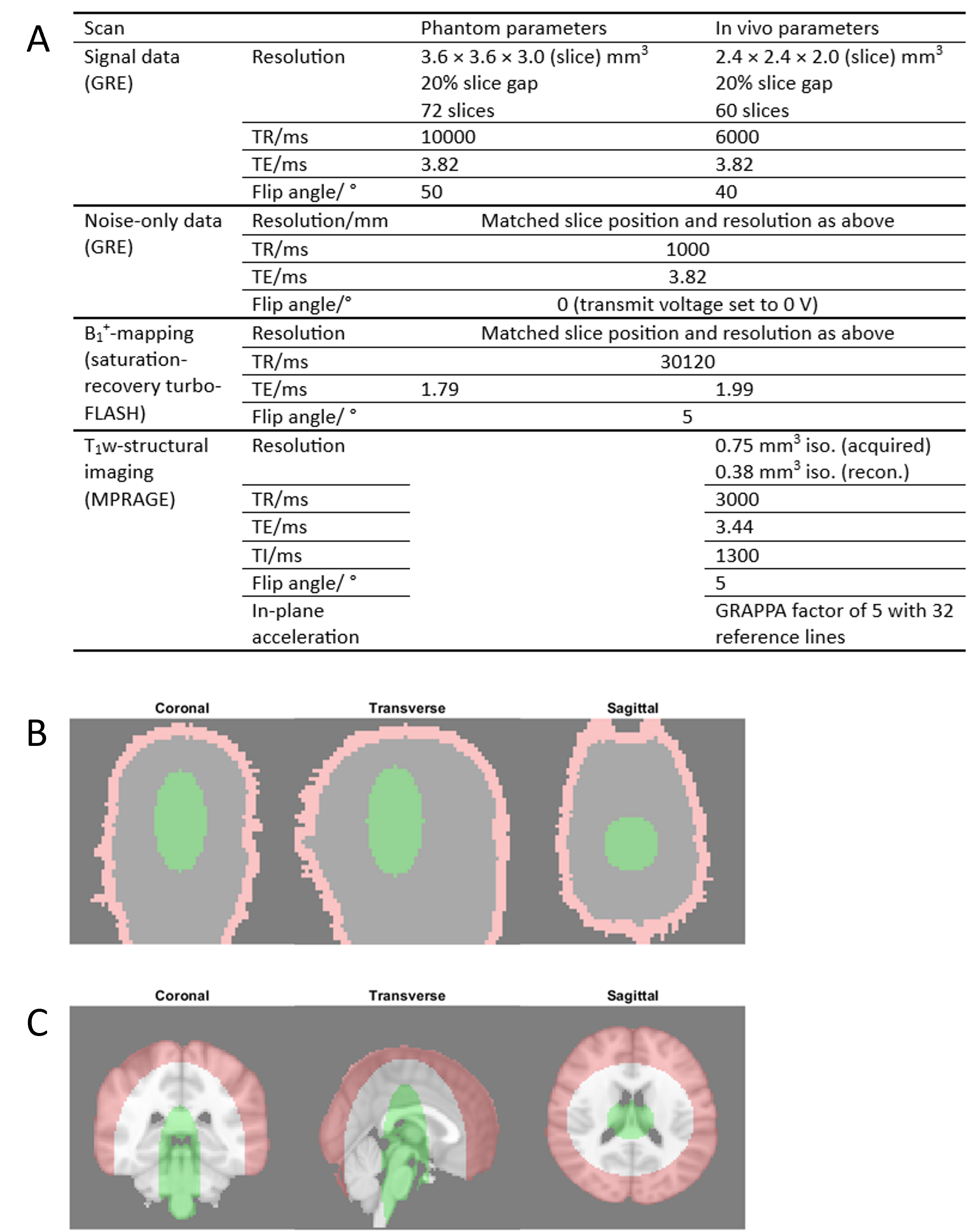
Two regions-of-interest(ROIs), "edge" and "centre", were defined for performance comparison (Figure 1).
In vivo
Two healthy volunteers underwent four sessions, following a protocol similar to the phantom experiment, with the addition of a T1-weighted (T1w) structural imaging sequence. SNR and g-factor maps were obtained and registered to MNI152 standard space via the T1w and signal images using FLIRT in FSL. Acquisition parameters are provided in Figure 1.
Results
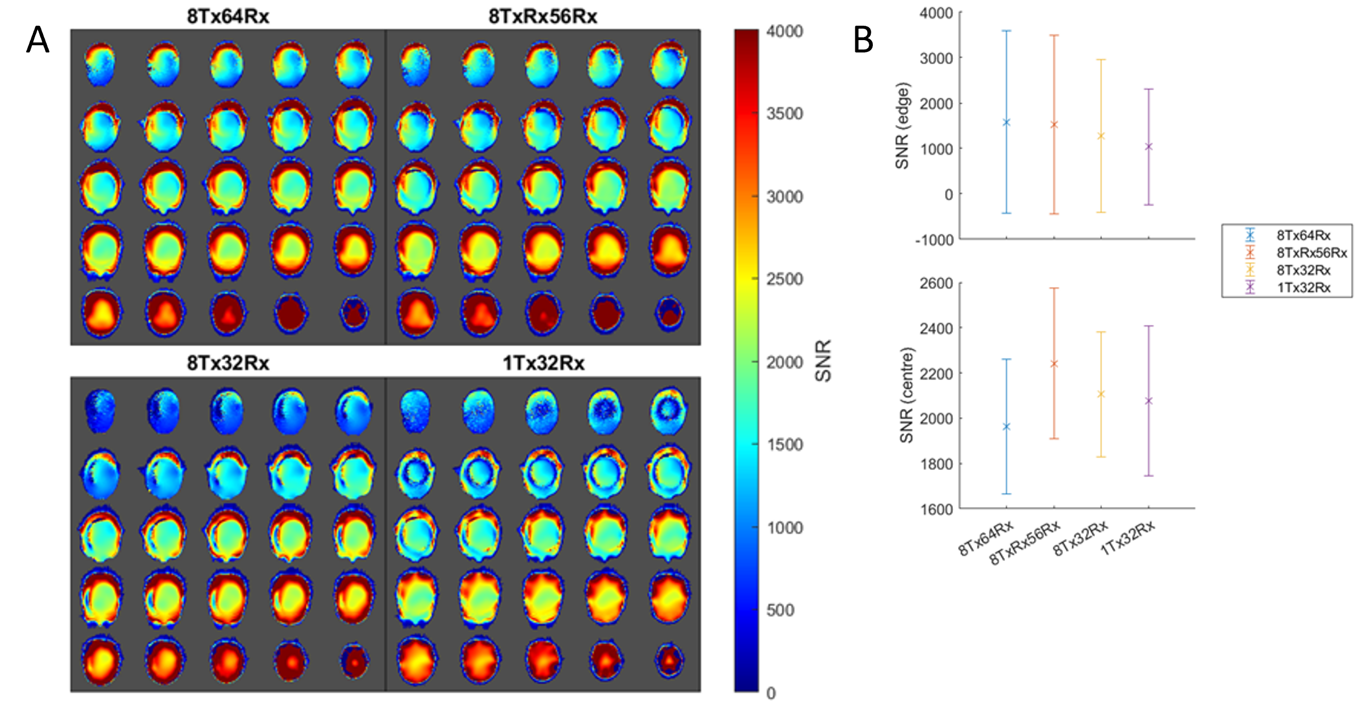
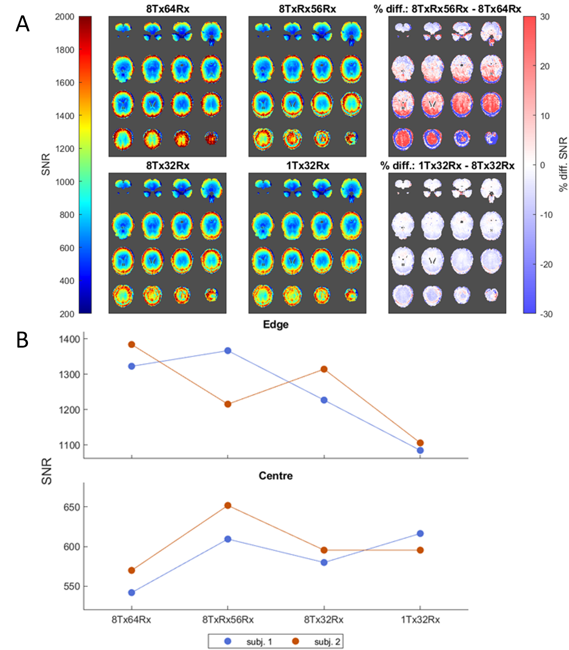
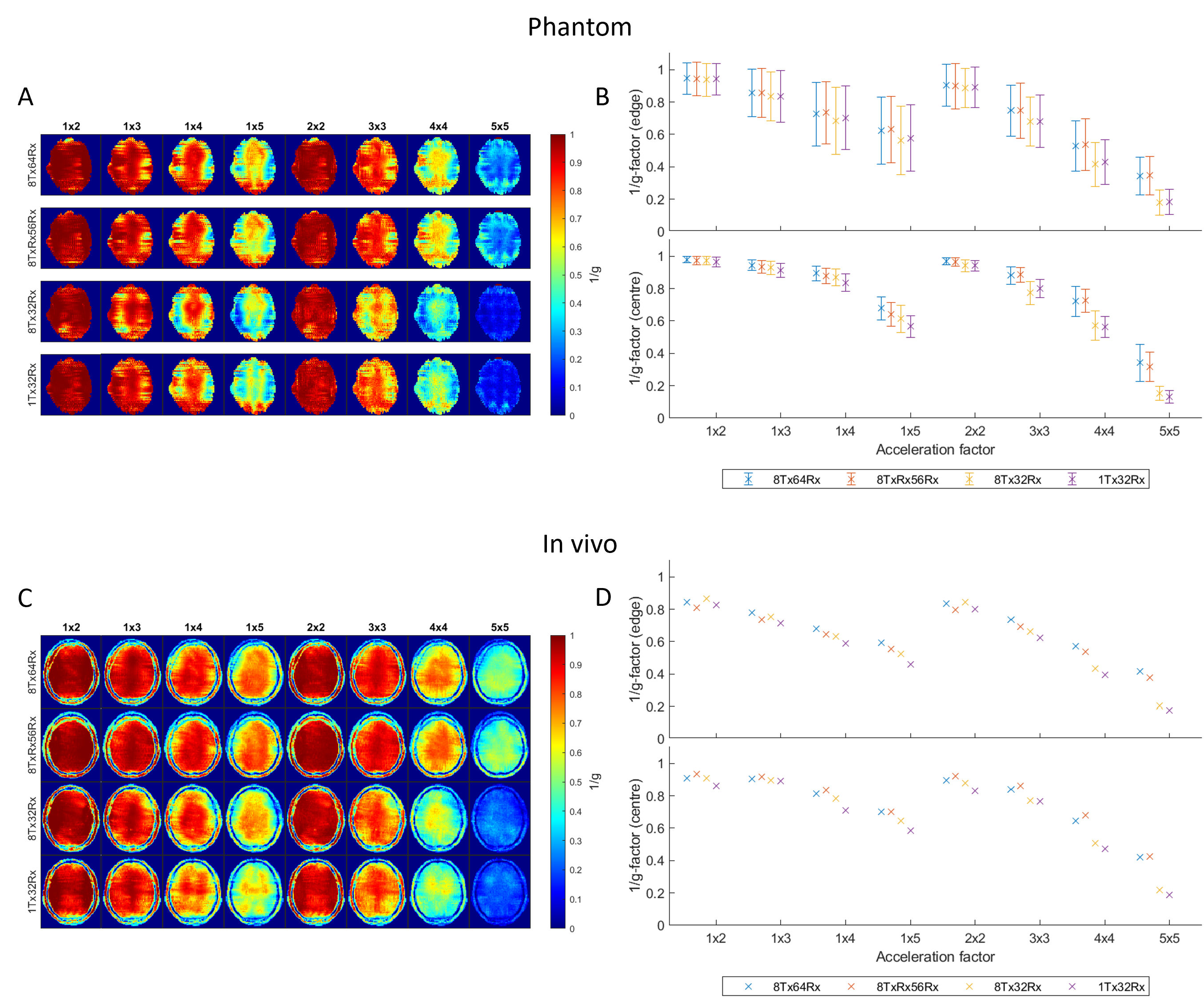
The phantom SNR maps are depicted in Figure 2A. The 8TxRx56Rx coil exhibited a -3.6% decrease in peripheral SNR and 13.3% increase in central SNR when compared to the 8Tx64Rx coil. In vivo results with 8TxRx56Rx show a -4.7% decrease in peripheral SNR and 12.6% increase in central SNR (Figure 3).Figures 4A and B present 1/g-factor maps for phantom and in vivo acquisitions and Figures 4C and D compare the central and edge 1/g-factor. There was a strong agreement between the phantom and in vivo results.
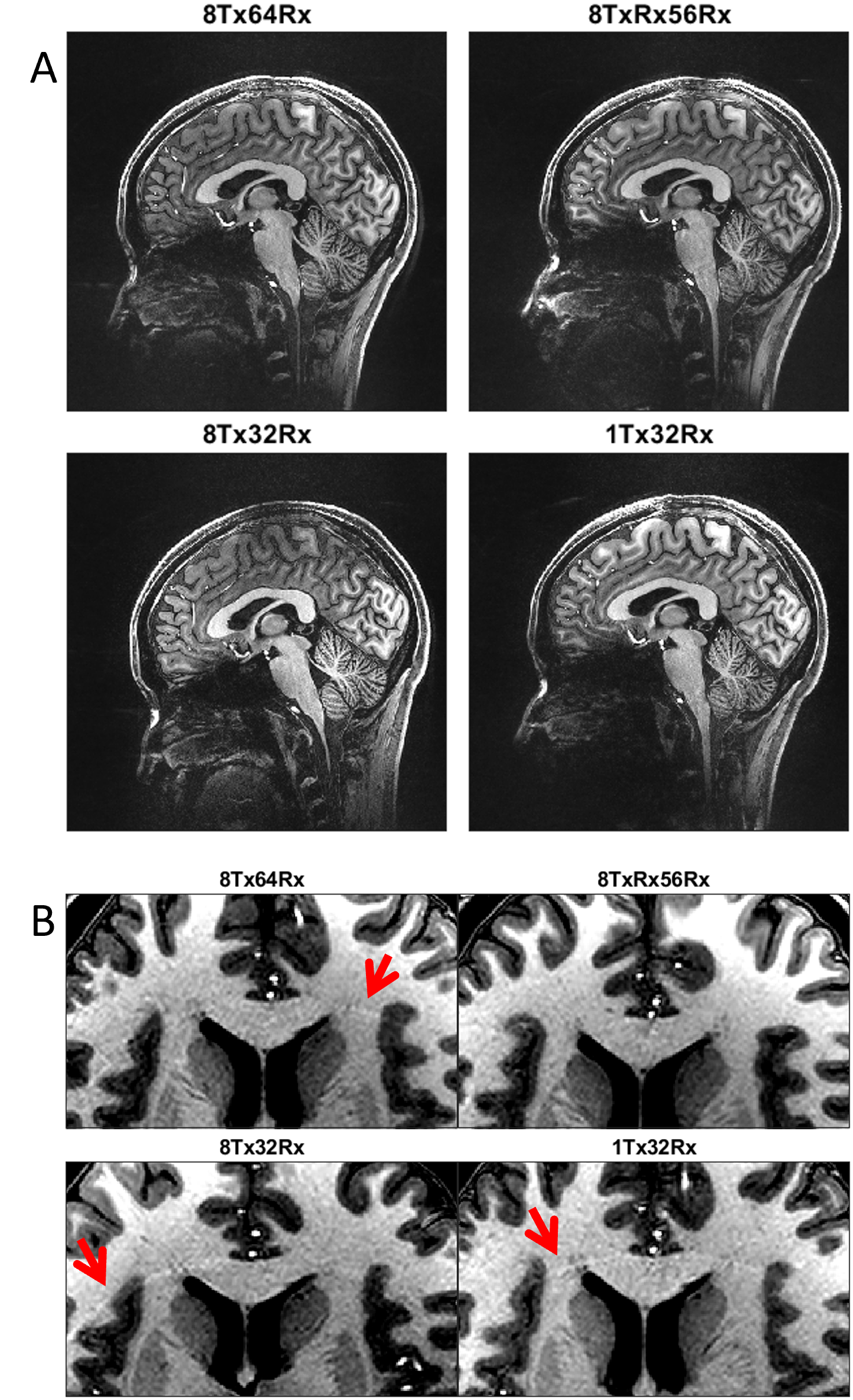
Figure 5 shows T1w-structural images from one volunteer. All images had acceptable diagnostic quality despite the high GRAPPA factor used. Figure 5B shows a zoomed-in where mild parallel imaging artifacts can be seen in all but the 8TxRx56Rx coil.
Discussion
This study compared the performance of a modified 8TxRx56Rx coil with three conventional ToRo arrays. The results show that the modified 8TxRx56Rx coil exhibits greater central SNR with minimal loss of peripheral SNR for both phantom and in vivo scans compared to a ToRo design. The enhanced central SNR can be attributed to two factors: 1) larger transceive loops, which increase penetration depth, and 2) the anterior part of the receive array has elements until the eye loops, whereas the transceive loops are circumferential around the whole brain.All coils exhibited similar g-factor performance with low acceleration factors, but the 64-channel receive coils outperformed their 32-channel counterparts at high acceleration factors. Notably, no significant distinction in performance was observed between the 8Tx64Rx and 8TxRx56Rx coils. In parallel imaging, g-factor arises from coil sensitivities similarities. There were initial concerns that the increased spatial overlap between the 8TxRx and 56Rx elements might diminish sensitivity differences compared to ToRo coils. However, the new coil design effectively preserved the advantages of the 64Rx channel configuration. This observation is further substantiated by the absence of parallel imaging artifacts in highly accelerated acquisitions.
Conclusion
In this abstract, we have presented the first study showing that a 56-channel receive 8-channel loop-based transceiver array offers central SNR gains with minimal penalties to peripheral SNR and g-factors compared to a conventional 8Tx64Rx coil at 7T.Acknowledgements
No acknowledgement found.References
1. Gosselink, M., Hoogduin, H., Froeling, M. & Klomp, D. W. J. No need to detune transmitters in 32-channel receiver arrays at 7 T. NMR Biomed 34, e4491 (2021).
2. Avdievich, N. I. et al. A 32-element loop/dipole hybrid array for human head imaging at 7 T. Magnetic Resonance in Medicine 88, 1912–1926 (2022).
3. Lagore, R. L. et al. An 8 Dipole Transceive and 24 Loop Receive Array for Non-Human Primate Head Imaging at 10.5T. NMR Biomed 34, e4472 (2021).
4. Lagore RL et al., ISMRM 2023
5. Lakshmanan, K. et al. The “Loopole” Antenna: A Hybrid Coil Combining Loop and Electric Dipole Properties for Ultra-High-Field MRI. Concepts in Magnetic Resonance Part B, Magnetic Resonance Engineering 2020, e8886543 (2020).
6. Uğurbil, K. et al. Brain imaging with improved acceleration and SNR at 7 Tesla obtained with 64-channel receive array. Magn Reson Med 82, 495–509 (2019).
7.Williams, S. N. et al. A nested eight-channel transmit array with open-face concept for human brain imaging at 7 tesla. Frontiers in Physics 9, (2021).
8. Gunamony S et al., ISMRM 2022
9. Kellman, P. & McVeigh, E. R. Image reconstruction in SNR units: A general method for SNR measurement†. Magnetic Resonance in Med 54, 1439–1447 (2005).
10.Roemer, Pruessmann, K. P., Weiger, M., Scheidegger, M. B. & Boesiger, P. The NMR phased array. Magn. Reson. Med. 16, 192–225 (1989).
11.Pruessmann, K. P., Weiger, M., Scheidegger, M. B. & Boesiger, P. SENSE: Sensitivity encoding for fast MRI. Magnetic Resonance in Medicine 42, 952–962 (1999).
Figures