1033
Capturing Central uiSNR at Ultrahigh Field: Number and Size of the Receive Elements Matter1Center for Magnetic Resonance Research (CMRR), University of Minnesota, Minneapolis, MN, United States, 2Bernard and Irene Schwartz Center for Biomedical Imaging, Department of Radiology, New York University Grossman School of Medicine, New York, NY, United States, 3Center for Advanced Imaging Innovation and Research (CAI2R), Department of Radiology, New York University Grossman School of Medicine, New York, NY, United States
Synopsis
Keywords: RF Arrays & Systems, RF Arrays & Systems
Motivation: In addition to peripheral SNR gain, the promise of a quadratic increase of SNR at the center of a human head with field strength draws significant attention to many ultrahigh field head MRI applications.
Goal(s): Assess the performance of state-of-the-art RF receive array coils in capturing the theoretical upper limit of central head SNR across different field strengths.
Approach: We experimentally investigated the impact of combining transceiver elements with highly-dense conventional loop arrays to capture the ultimate intrinsic SNR in head applications.
Results: We demonstrated that achieving central SNR gains at UHF requires an increased number of receive elements and larger transceiver elements.
Impact: Capability of conventional loop technology to capture the SNR's upper-limit in human head is investigated across different field strengths, which can pave the way for the RF technology developments focused on capturing the SNR gain in ultrahigh field head applications.
Introduction
The promise of increased SNR1-3 with higher field strengths, particularly in ultrahigh field (UHF) MRI (≥7T), has garnered significant attention for head imaging applications. Calculations of ultimate intrinsic SNR (uiSNR)3—the highest achievable SNR—at the center of a uniform spherical phantom4,5 demonstrated that uiSNR increases almost quadratically with field strength (B0).Analytic calculations6 suggest that conventional RF coil technology, based on an array of loops, can capture over 90% of the uiSNR at the center of a tissue-mimicking sphere. Simulation results7 indicate that receiver coils with varying loop element numbers (from 8 to 96) capture central uiSNR almost equally across different B0 (from 1.5T to 9.4T). Despite theoretical predictions, our previous experimental study8 revealed that a state-of-the-art 64-channel loop receiver array falls short of achieving the expected quadratic central SNR increase when transitioning from 7T to 10.5T.
In order to re-capture the quadratic central SNR gain at 10.5T, we proposed to combine the transceiver elements with highly-dense loop arrays. As a result, significant SNR gains were achieved at the center9-11. In this study, we experimentally evaluate the SNR performance of these arrays with respect to the uiSNR. In addition, we evaluate absolute performance for a variety of commercial and custom-built receiver arrays with different numbers of elements at 3T and 7T.
Methods
MRI ScannersMRI experiments were conducted at 3T (Prisma, Siemens Healthineers), 7T (Magnetom, Siemens Healthineers), and 10.5T (Magnetom, Siemens Healthineers).
3T Receiver Coils
SNR measurements at 3T were performed using three commercial receiver coils (Siemens Healthineers): 20-channel head/neck, 32-channel head, and 64-channel head/neck coils.
7T Receiver Coils
SNR measurements at 7T were performed using one commercial and one custom-built receiver coil: 32-channel head coil (Nova Medical) and 64-channel head coil12 (custom-built).
10.5T Receiver Coils
SNR measurements at 10.5T were performed using four custom-built receiver coils: 32-channel13, 64-channel9, 80-channel9, and 128-channel10 head coils. Note that in the 80-ch and 128-ch arrays, 16 large transceiver loop elements were incorporated into the receive array.
SNR Measurements and Analyses
All SNR measurements were performed inside a polyvinylpyrrolidone (PVP)-based uniform lightbulb-shaped phantom13. The electrical properties of the phantom were measured as follows: 3T—(εr=55, σ=0.47S/m); 7T—(εr=51, σ=0.56S/m); 10.5T—(εr=48, σ=0.65S/m).
SNR was reconstructed from fully sampled 2D-GRE sequences with TR=10000ms, TE=3.48ms, full bandwidth=87kHz, voxel size = 2.0×1.0×2.0mm3. Noise images were acquired with identical parameters, but no RF excitation and TR of 600ms. To compare the measured SNR with the uiSNR, the former was scaled by the experiment-related parameters as described in Refs. [14,15]:
$$\zeta_{Scld}(\bar r) = \zeta_{Meas}(\bar r) \times \frac{F\sqrt {\Delta f} }{V_{vxl}\sqrt {N_{acq}NEX} \sin(\alpha(\bar r))} \times \frac{1}{\rho e^{-{TE}/{T2\mbox{*}}}}$$
The uiSNR was numerically calculated16 as a metric to assess the SNR performance of the coils across the field strengths.
To evaluate the SNR performances of the coils at different depths from the surface of the phantom, 3D SNR data were averaged inside lightbulb-shaped shell ROIs with a thickness of 1cm at different depths. Central SNR was averaged inside a sphere with a 1cm radius.
Results
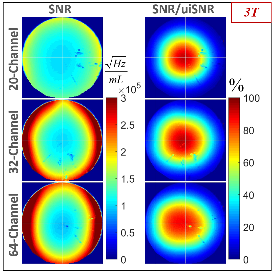
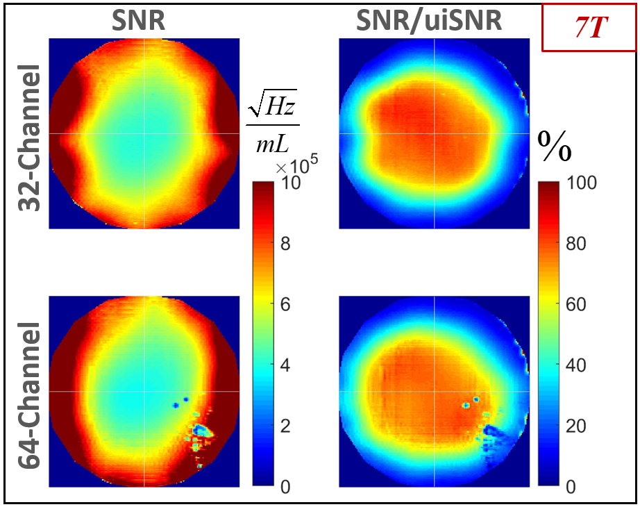
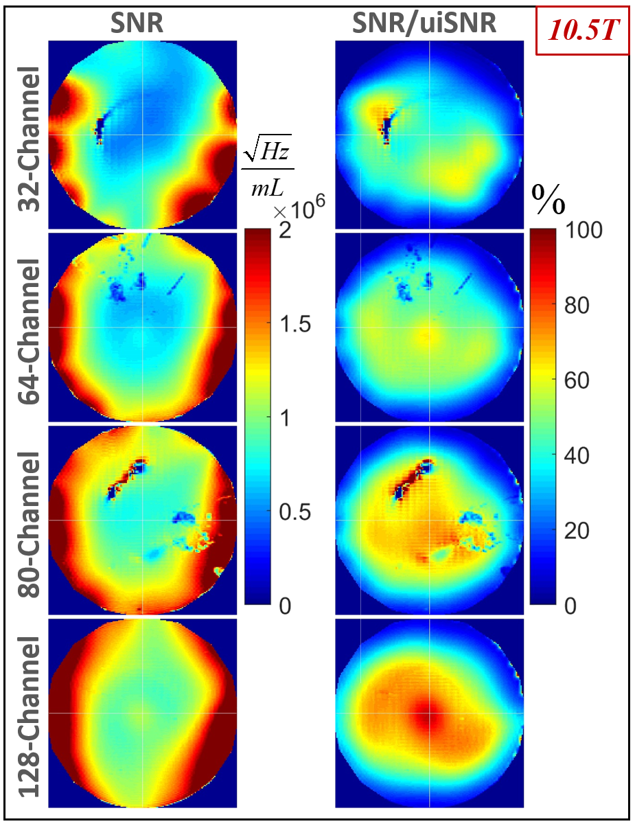
Figure 1 shows the axial view of the intrinsic SNR maps measured (left column) and normalized to the properly scaled corresponding uiSNR map (right column) for the 3T coils.Similarly, Figure 2 and Figure 3 demonstrate coil performance maps at 7T and 10.5T, respectively.
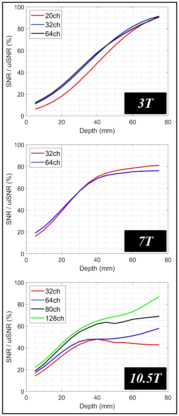
Figure 4 presents a comparison between the absolute SNR performance of the coils under investigation at different depths.
Discussions and Conclusion
In this study, we experimentally investigated the capability of conventional loop technology to capture the uiSNR at the center of the head in UHF applications. Note that there are two sources of uncertainties in the scaling factor in Equation 1. The F (Noise Factor of the receive chain) is difficult to measure accurately: we used 1.15, which is the noise factor of the pre-amplifiers. We measured an average T2* of 24ms in the PVP phantom at 10.5T (it was linearly extrapolated to 84ms and 36ms for 3T and 7T), however, its value can vary considerably, especially in peripheral regions.The 3T coils’ central SNR performance (>90%) is in agreement with the theoretical prediction. Whereas at 10.5T, the 64-channel loop receiver array only captured 58% of the central uiSNR. However, incorporating 16 large transceiver loop elements into the 64-ch array boosted the central SNR performance to ~70%, which is closer to the simulation results. Moreover, incorporating the 16 transceiver loop elements into 112-ch smaller loop elements to compose a 128-ch receive array resulted in capturing ~90% of central uiSNR. This demonstrates that achieving central uiSNR at higher field strengths requires an increased number of loop receive elements and/or combination with larger elements.
Acknowledgements
This work was supported by the following grants: NIH P41 EB027061, NIH R01 NS115180, NIH R01 EB024536 and NIH U01 EB025144.References
1. Vaughan JT, Garwood M, Collins CM, Liu W, DelaBarre L, Adriany G, Andersen P, Merkle H, Goebel R, Smith MB. 7T vs. 4T: RF power, homogeneity, and signal‐to‐noise comparison in head images. Magnetic Resonance in Medicine: An Official Journal of the International Society for Magnetic Resonance in Medicine. 2001;46(1):24-30.
2. Pohmann R, Speck O, Scheffler K. Signal‐to‐noise ratio and MR tissue parameters in human brain imaging at 3, 7, and 9.4 tesla using current receive coil arrays. Magnetic resonance in medicine. 2016;75(2):801-9.
3. Ocali O, Atalar E. Ultimate intrinsic signal‐to‐noise ratio in MRI. Magnetic resonance in medicine. 1998;39(3):462-73.
4. Lee HH, Sodickson DK, Lattanzi R. An analytic expression for the ultimate intrinsic SNR in a uniform sphere. Magnetic resonance in medicine. 2018;80(5):2256-66.
5. Hoult DI. Sensitivity and power deposition in a high‐field imaging experiment. Journal of Magnetic Resonance Imaging. 2000;12(1):46-67.
6. Lattanzi R, Sodickson DK. Ideal current patterns yielding optimal signal‐to‐noise ratio and specific absorption rate in magnetic resonance imaging: computational methods and physical insights. Magnetic resonance in medicine. 2012;68(1):286-304.
7. Vaidya MV, Sodickson DK, Lattanzi R. Approaching ultimate intrinsic SNR in a uniform spherical sample with finite arrays of loop coils. Concepts in Magnetic Resonance Part B: Magnetic Resonance Engineering. 2014 Aug;44(3):53-65.
8. Sadeghi-Tarakameh A, Grant A, Waks M, et al. Central SNR Gain from the Field Strength: Evaluation of Current RF Coil Technology. Proceedings of the International Society of Magnetic Resonance for Medicine 31, Toronto, ON, Canada. June 2023. ISMRM; 2023:4579.
9. Waks M, Lagore R, Auerbach E, et al. A Self-Decoupled 16-Channel Transmit, 80-Channel Receive Array For 10.5 Tesla Human Head Imaging. Proceedings of the International Society of Magnetic Resonance for Medicine 31, Toronto, ON, Canada. June 2023. ISMRM; 2023:0211.
10. Lagore RL, Grant A, DelaBarre L, et al. 128-Channel Brain Imaging Array With Improved Acceleration At 10.5 Tesla. Proceedings of the International Society of Magnetic Resonance for Medicine 31, Toronto, ON, Canada. June 2023. ISMRM; 2023:1059.
11. Sadeghi-Tarakameh A, Waks M, Grant A, et al. Boosting Central Head SNR At 10.5T: 32-Channel Hybrid RF Coil Comprised Of 25 Rx-Only Loops And 7 TxRx NODES Dipoles. Proceedings of the International Society of Magnetic Resonance for Medicine 31, Toronto, ON, Canada. June 2023. ISMRM; 2023:3913.
12. Uğurbil K, Auerbach E, Moeller S, Grant A, et al. Brain imaging with improved acceleration and SNR at 7 Tesla obtained with 64‐channel receive array. Magnetic resonance in medicine. 2019 Jul;82(1):495-509.
13. Tavaf N, Jungst S, Lagore RL, Radder J, Moeller S, Grant A, Auerbach E, Ugurbil K, Adriany G, Van de Moortele PF. A Self-decoupled 64 Channel Receive Array for Human Brain MRI at 10.5T. In Proceedings of the 2021 ISMRM & SMRT Annual Meeting & Exhibition, 2021: 0179.
14. Lattanzi R, Grant AK, Polimeni JR, Ohliger MA, Wiggins GC, Wald LL, Sodickson DK. Performance evaluation of a 32‐element head array with respect to the ultimate intrinsic SNR. NMR in Biomedicine: An International Journal Devoted to the Development and Application of Magnetic Resonance In vivo. 2010 Feb;23(2):142-51.
15. Gruber B, Stockmann JP, Mareyam A, Keil B, Bilgic B, Chang Y, Kazemivalipour E, Beckett AJ, Vu AT, Feinberg DA, Wald LL. A 128‐channel receive array for cortical brain imaging at 7 T. Magnetic Resonance in Medicine. 2023 Dec;90(6):2592-607.
16. Georgakis IP, Villena JF, Polimeridis AG, Lattanzi R. Novel Numerical Basis Sets for Electromagnetic Field Expansion in Arbitrary Inhomogeneous Objects. IEEE Transactions on Antennas and Propagation. 2022 May 30;70(9):8227-41.
Figures