1032
First experimental results using RF Elements with Switching Transmit Sensitivities at ultrahigh field MRI1MPI for Biological Cybernetics, Tübingen, Germany, 2University Hospital Tübingen, Tübingen, Germany, 3Institute of Neuroradiology, Universitätsklinikum Erlangen, Friedrich-Alexander Universität Erlangen-Nürnberg, Erlangen, Germany
Synopsis
Keywords: Parallel Transmit & Multiband, High-Field MRI
Motivation: Dipole RF elements with electronically switchable B1 field patterns have been shown to improve receive performance. The question whether they are beneficial for transmission is still open.
Goal(s): Improve flip angle homogeneity by modulating the Tx sensitivity of a dipole during excitation.
Approach: An RF coil built from eight dipoles with electronically switchable sensitivities was constructed. Achievable flip angle homogeneity with 2-kT-points pulses was evaluated in simulations and in experiments.
Results: Flip angle homogeneity could be increased by electronically switching the Tx sensitivity during the course of the RF pulse.
Impact: RF elements with switchable transmit sensitivities offer a novel degree of freedom for excitation that promises improved flip angle homogeneity. This addresses one of the most pressing problems in ultra-high field MRI.
Introduction
The concept of rapidly reconfigurable radio frequency (RF) receiver elements for ultrahigh-field MRI offers improved parallel imaging performance1. In this study, a first attempt is made to use fast switching coaxial dipoles for transmission. In contrast to the receive application, the use of fast switching transmit coils aims at improving flip angle (FA) homogeneity, which is a major challenge in ultrahigh-field MRI. In a previous study 2, we evaluated fast switching dipoles in simulations (Figure 4). Here we present first experimental results, both in a phantom and in-vivo.Coil design
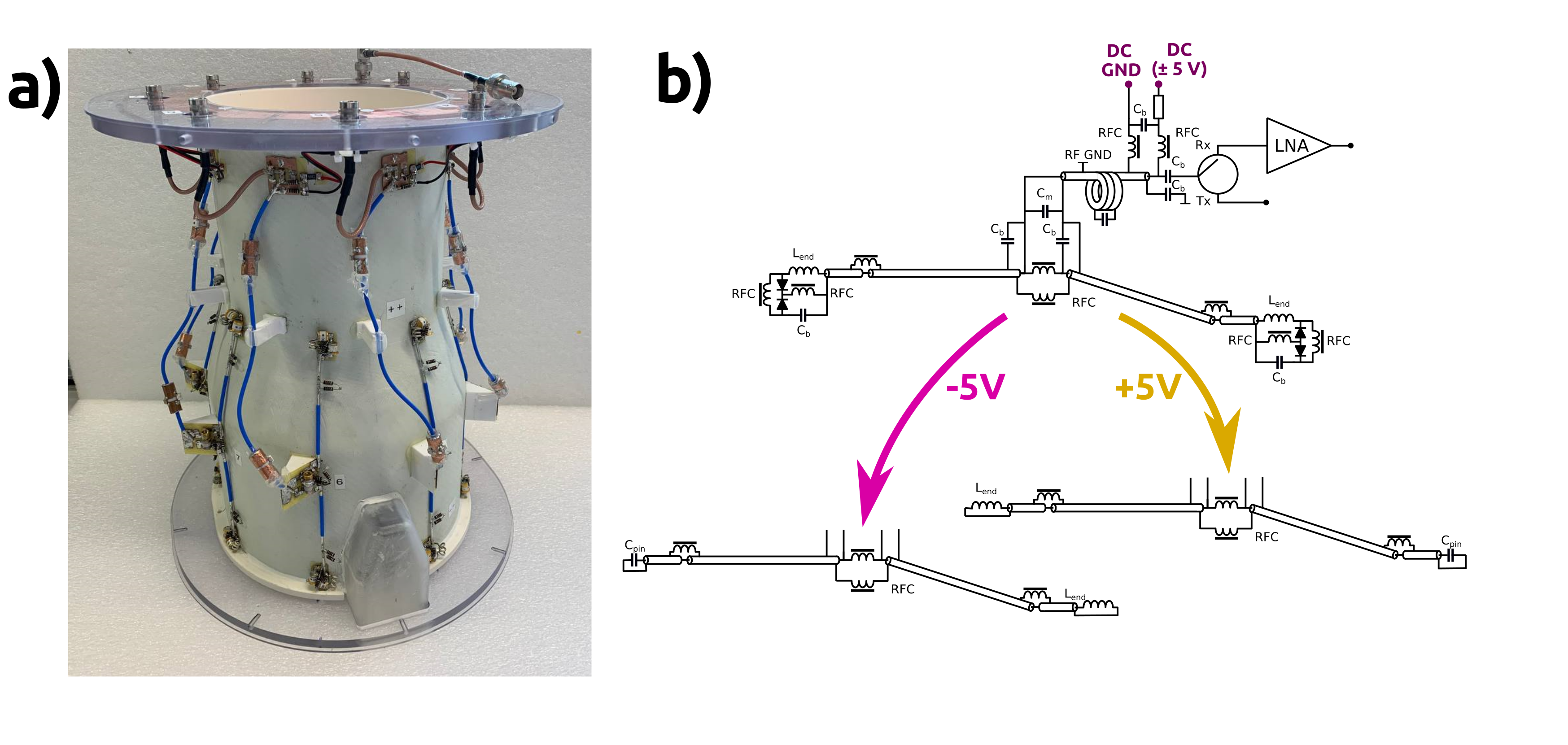
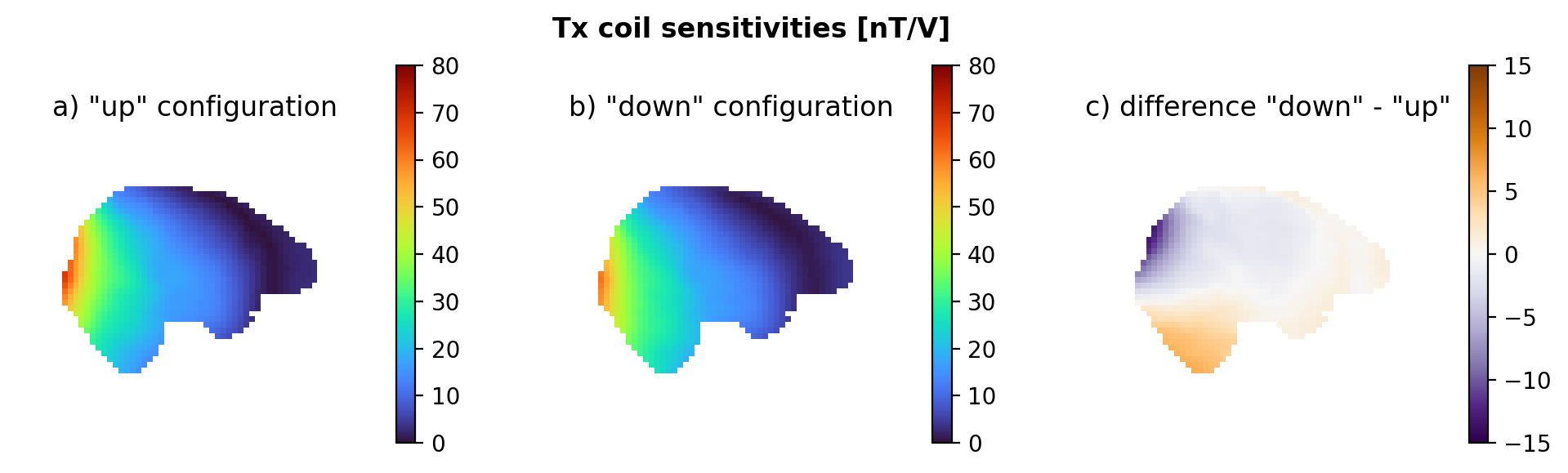
Dipole elements with a circuit that allows switching between inductive and capacitive impedance were designed similar to1, closely following3. The current distribution in the dipoles is biased toward the inductive end, resulting in a spatial shift of the B1+ sensitivity in the same direction (Figure 1). In a simulation study, four different head array coils with eight dipoles each were evaluated, varying the dipole length between 17 cm and 19 cm, and including or omitting a reflector above the dipoles. Simulations were performed for 400 MHz in CST Studio using the Duke voxel model and resulted in 2 sets of sensitivity profiles for each coil: “up” and “down”, where all sensitivity profiles were shifted in the cranial/caudal direction (Figure 2). Based on the simulation results, a 17 cm array with reflector was constructed. A custom CMOS driver was used for switching the dipoles between up and down configuration.Pulse design and MRI measurements
Experiments were performed on a Siemens 9.4 T whole-body MRI scanner. Switching between the up and down state was controlled from the sequence via an optical trigger signal. All MR sequences were written in a modified version of pulseq that allows pTx RF-shimming for each RF pulse4. Single-channel B1+ and B0 maps were acquired using a presaturated turbo-flash sequence with weighted hybrid mapping5. B1+ and B0 mapping was performed both in a head-shaped agar phantom and in a healthy male subject. A homogeneous FA distribution of 10° throughout the brain was chosen as the optimization target. The normalized root mean square error (nRMSE) of the obtained FA distribution was used as a quality metric, excluding outliers. The optimization was performed similarly to the spatial domain method6, using the variable exchange method7 to solve the magnitude-least-squares problem with 20 iterations on a Tikhonov-regularized minimization. Optimization was performed for the entire volume in the phantom and for the brain only in-vivo. For excitation, 2-kT-points pulses were designed. Fast switching during the pulse was implemented by changing the coil profiles from up to down configuration after half the excitation time. In this case, magnitude and phase were optimized for each subpulse. The k-space location of the first kT-point was chosen by randomly generating 25,000 k-space positions in the range 28 m-1 ≤ kx,y,z ≤ 28 m-1 and selecting the one that gave the best performance for each scenario. The second kT-point was positioned in the center of k-space. For comparison, a similar pulse was designed for the static “down”-configuration without fast switching. For evaluating excitation homogeneity experimentally a gradient echo sequence (FA=2°, TR=11 ms, TE=1.5 ms) was used on the phantom.Results
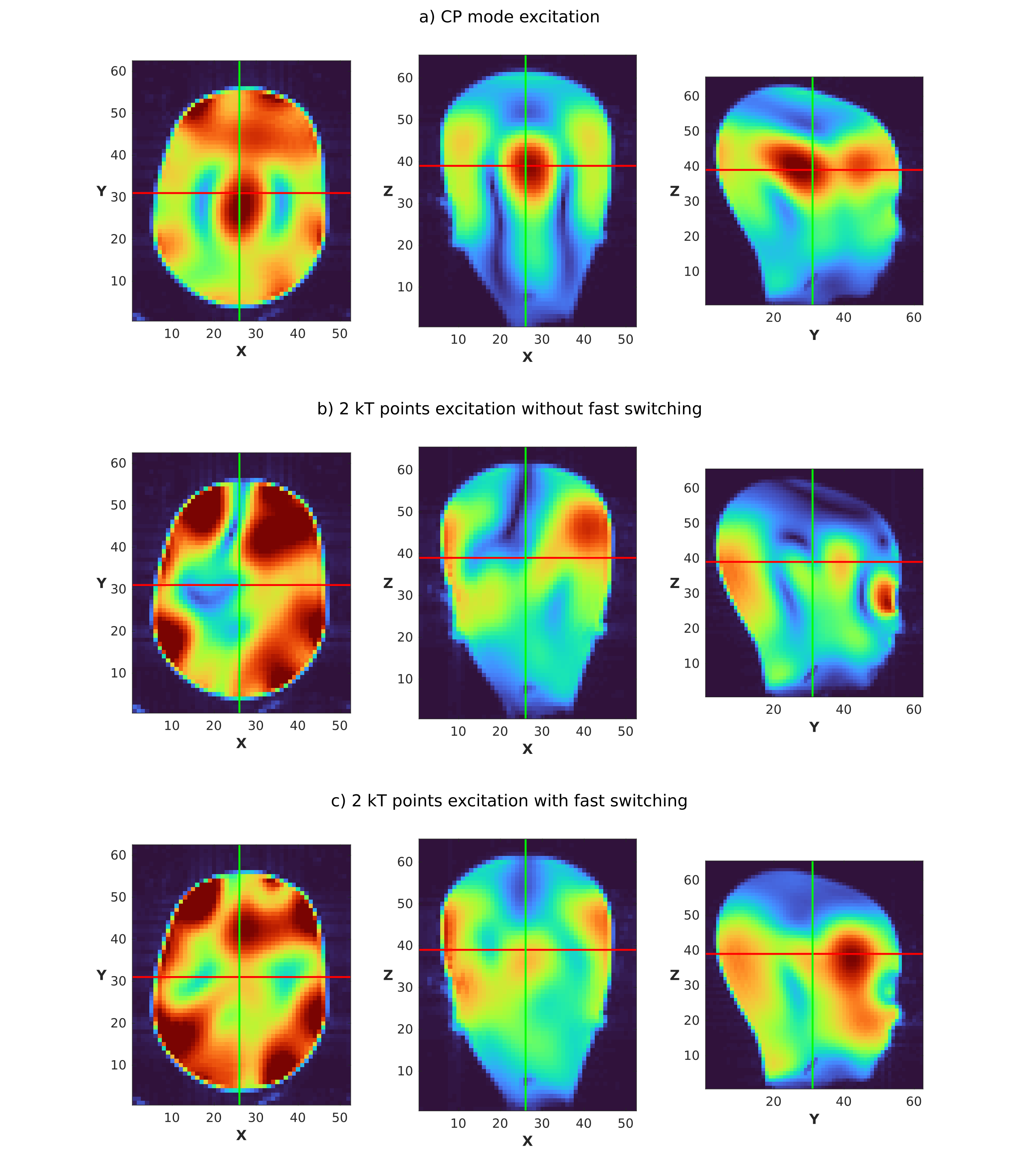
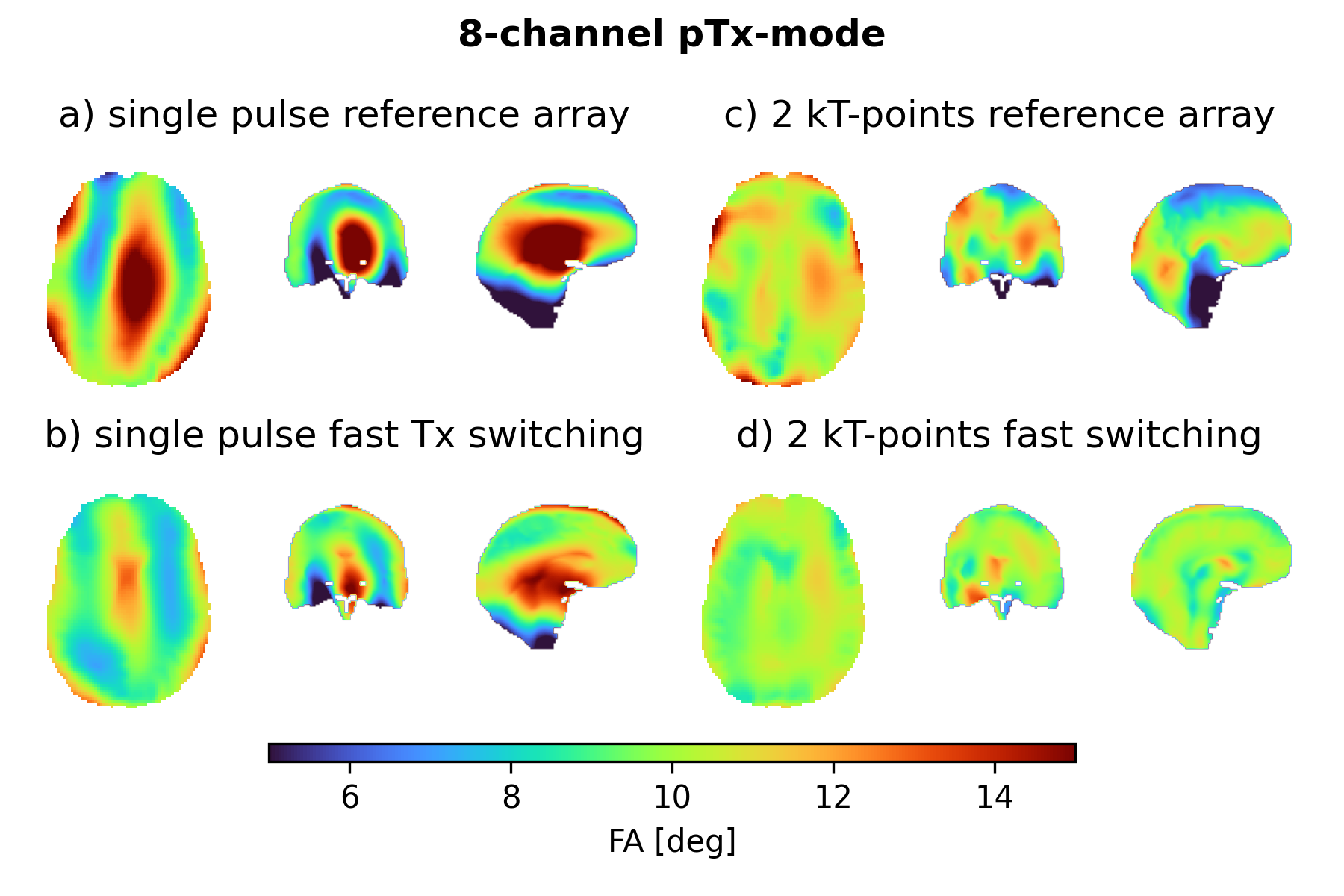
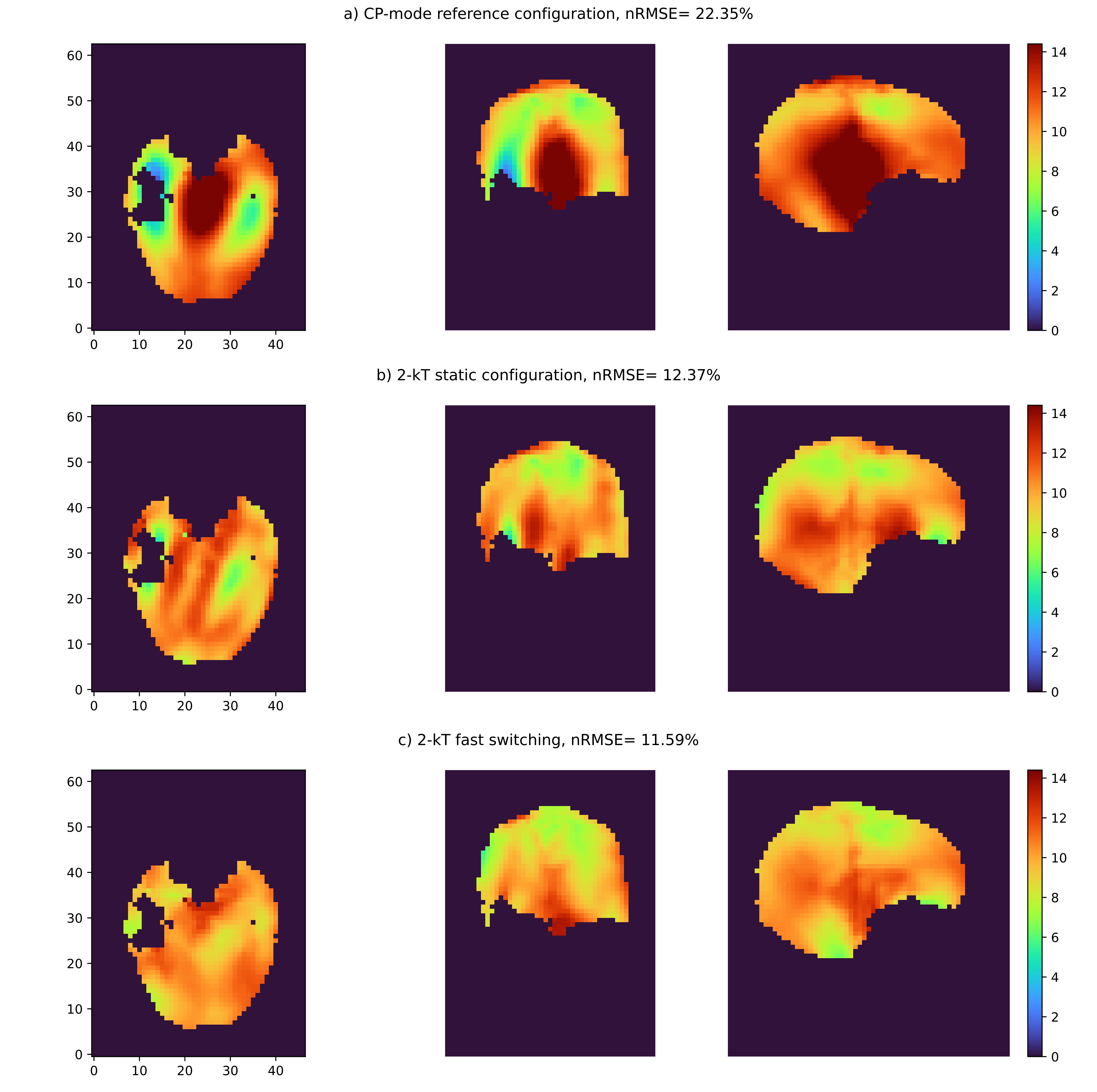
In the agar phantom, optimizing the 2-kT-point pulses resulted in an nRMSE of 17.12% and 15.61% for the static and the fast-switching scenario, compared to 80.82% in CP-mode. The pulses were played out successfully in a gradient echo sequence and the resulting images matched the simulated FA distributions well (Figure 3). When optimizing pulses for the in-vivo data, nRMSE was reduced to 12.37% and 11.59% for static and fast-switching, compared to 22.35% in CP-mode (Figure 5).Discussion and Conclusion
In simulations (Figure 4), the introduction of transmit elements with rapidly switchable B1+ sensitivities allows for a significant reduction in FA inhomogeneity in ultrahigh-field MRI. Compared to the simulation results the effect of fast switching stays well below expectations both in-vivo and in the phantom. Compared to the previously published simulation results the difference of up and down sensitivities is much lower under experimental conditions, which needs to be investigated next. We were, however, able to demonstrate that the concept works not only in simulations but also experimentally. Similar to the observations made with reconfigurable Rx elements, switching between different Tx sensitivity patterns within a single element can be seen as a way to effectively emulate a larger number of independent virtual Tx elements. Considering the cost and technical complexity of increasing the number of Tx channels, the use of rapidly switchable B1+ sensitivities in transmit elements should be further investigated.Acknowledgements
Funding by the Deutsche Forschungsgemeinschaft (DFG - German Research Foundation) under the Reinhart Koselleck Programme (DFG SCHE 658/12) and by the European Research Council (ERC Advanced Grant No 834940, SpreadMRI) is gratefully acknowledged.References
1. G.A. Solomakha et al 2023; ISMRM #5070
2. D. Bosch et al 2023; CMRR Workshop on UHF Imaging
3. G.A. Solomakha et al 2023; ISMRM #1061
4. M. Freudensprung et al 2023; ESMRMB #LT53
5. D. Bosch et al 2022; ISMRM #2865
6. W. Grissom et al 2006; Magn. Reson. Med., 56: 620-629
7. K. Setsompop et al 2008; Magn. Reson. Med., 59: 908-915
Figures