0960
Pushing contrast at low field with very high B11Biomedical Engineering & Imaging Sciences, King's College London, London, United Kingdom, 2Centre for the Developing Brain, King's College London, London, United Kingdom, 3Department of Neuroimaging, King's College London, London, United Kingdom
Synopsis
Keywords: New Signal Preparation Schemes, Low-Field MRI
Motivation: Inherently reduced SAR at low B0 fields opens the possibility for sequences employing high B1 to generate contrasts inaccessible on common systems.
Goal(s): Explore generation of magnetization transfer (MT) and inhomogeneous MT (ihMT) contrast using high B1 sequences on low-field MRI system.
Approach: A tuned resonator was used to enhance B1 fields locally within a 0.55T scanner. Rapid gradient-echo based MT/ihMT sequences were tested on ex-vivo lamb brain sample.
Results: Achieved ~9-fold increase in B1, boosting observed MTR/ihMTR. Unexpectedly, RF pulses failed to function at high B1 due to Bloch-Siegert and spin-locking; new pulse designs for this regime will form future work.
Impact: Using high B1 fields at low B0 enables contrasts that were previously off-limits due to safety constraints at high B0. To exploit these with clinical hardware we demonstrate a passive resonator that increases the B1 by a factor of 9.
Introduction
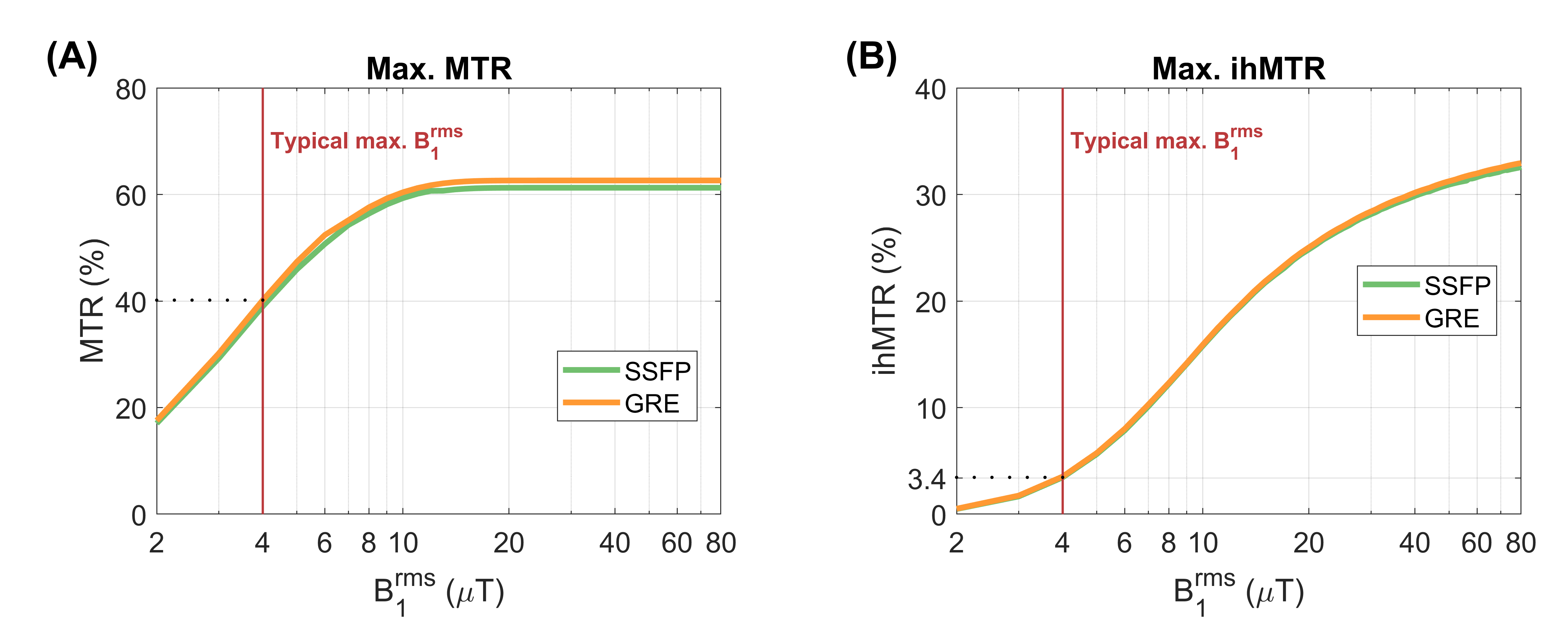
Lower field MRI has inherently reduced specific absorption rate (SAR) due to the lower Larmor frequency. While beneficial for safety, this also implies that applications requiring strong B1 fields become feasible, such as Magnetization transfer (MT) and inhomogeneous MT (ihMT). Figure 1 demonstrates simulated maximum MT and ihMT ratios (MTR/ihMTR) as a function of root-mean-square B1 (B1rms) using rapid gradient echo sequences at 0.55T. Typical maximum B1rms values on clinical scanners are around $$$4\mu{}T$$$ – it is clear that both contrasts could be substantially increased in proportion with B1rms.Based on the simplistic assumption that the maximum B1rms scales inversely with B0 squared, at 0.55T one might expect to safely achieve B1rms$$$\approx{}30\mu{}T$$$ . In practice, the maximum B1rms achievable for the commercial scanner used here is considerably less at $$$\approx{}4\mu{}T$$$ and determined by hardware limits. In order to reach the high B1 regime and resulting contrasts, we explore use of a passive resonator to locally enhance transmit efficiency (1).
Methods
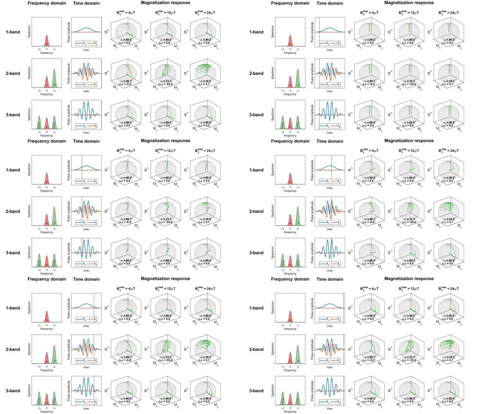
MT and ihMT contrast can be efficiently generated within rapid gradient echo sequences using non-selective multiband pulses to simultaneously excite and saturate (2) as illustrated in Figure 2. These pulses can have 1-band (1B), 2-bands (2B) or 3-bands (3B), such that they always generate the same flip angle whilst saturating the semisolid magnetization at different frequencies. MTR and ihMTR maps were computed from images acquired with each type of pulse:$$MTR(\%)=100\times{}\frac{s_{1B}-s_{3B}}{s_{1B}}$$
$$ihMTR(\%)=100\times{}\frac{s_{2B}-s_{3B}}{s_{1B}}$$
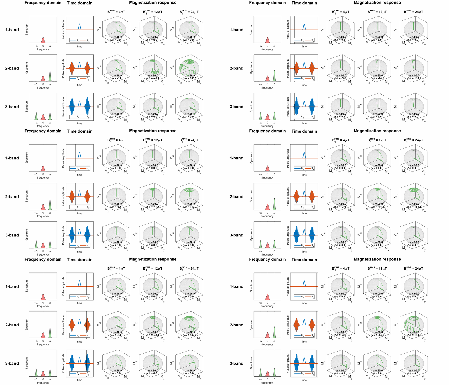
where $$$s_{\mathrm{x}B}$$$ is the signal acquired with a pulse with $$$\mathrm{x}$$$ bands. A second scheme in which saturation and excitation sub-pulses are separated is illustrated in Figure 3.
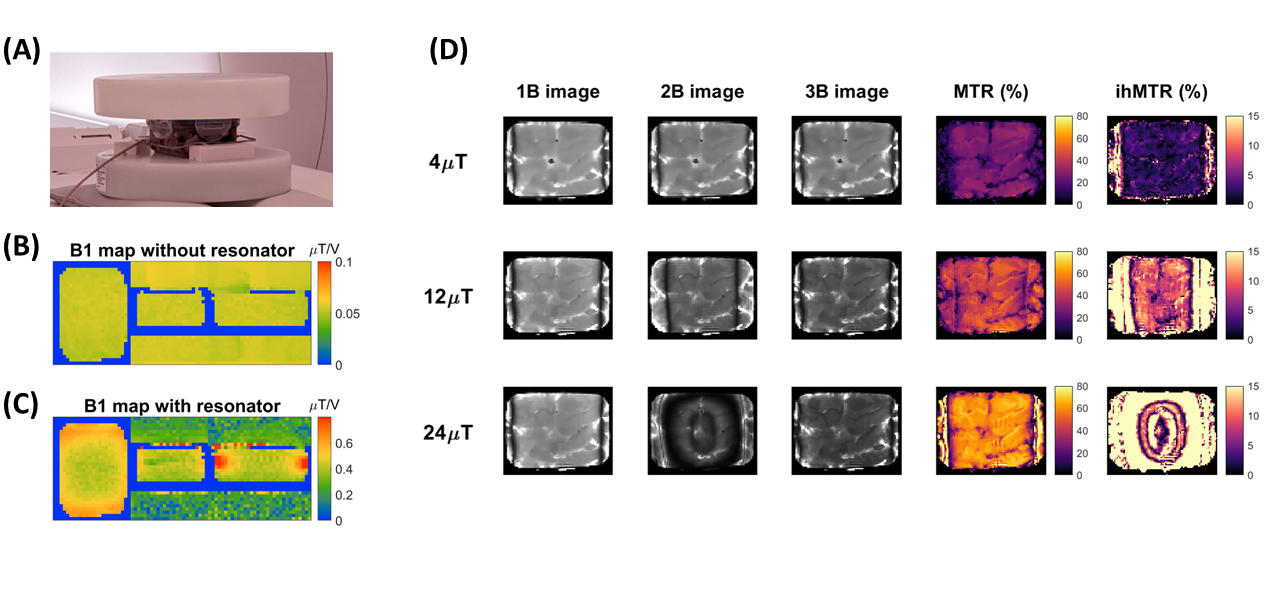
All experiments used a 0.55T scanner (MAGNETOM Free.Max, Siemens Healthineers, Erlangen, Germany). A square loop coil (11x11cm) tuned to 23.8MHz was positioned underneath the sample being imaged. Additional water phantoms were placed on top and beneath the resonator to load it correctly, and ex-vivo lamb brains inside containers filled with water were placed inside the resonator (Figure 4A). We acquired GRE and SSFP sequences for several B1rms levels and measured B1 using an AFI sequence (3).
Results & Discussion
Figure 4B,C illustrate B1 with and without the resonator; transmit efficiency increased by a factor of $$$9.2\pm2.8$$$ and $$$9.3\pm1.8$$$ in the two experiments.An initial experiment using multiband pulses (Fig 4D) with SSFP showed that MTR could be increased significantly with B1rms in line with predictions. However, it was found that ihMTR images contained significant artefacts, which can be seen to originate from the 2B images.
Bloch simulations (Figure 2 right side) showed as B1 increases the 2B pulses cause spin-locking, perturbing the intended trajectory. There is also a Bloch-Siegert (BS) shift generated by the off-resonance component which further interferes with SSFP imaging. These effects are absent for the 3B pulses. We hence switched to a separated pulse design (Figure 3) where the 2B pulses achieve their target flip angle (no spin-locking) but still generate a significant BS shift.
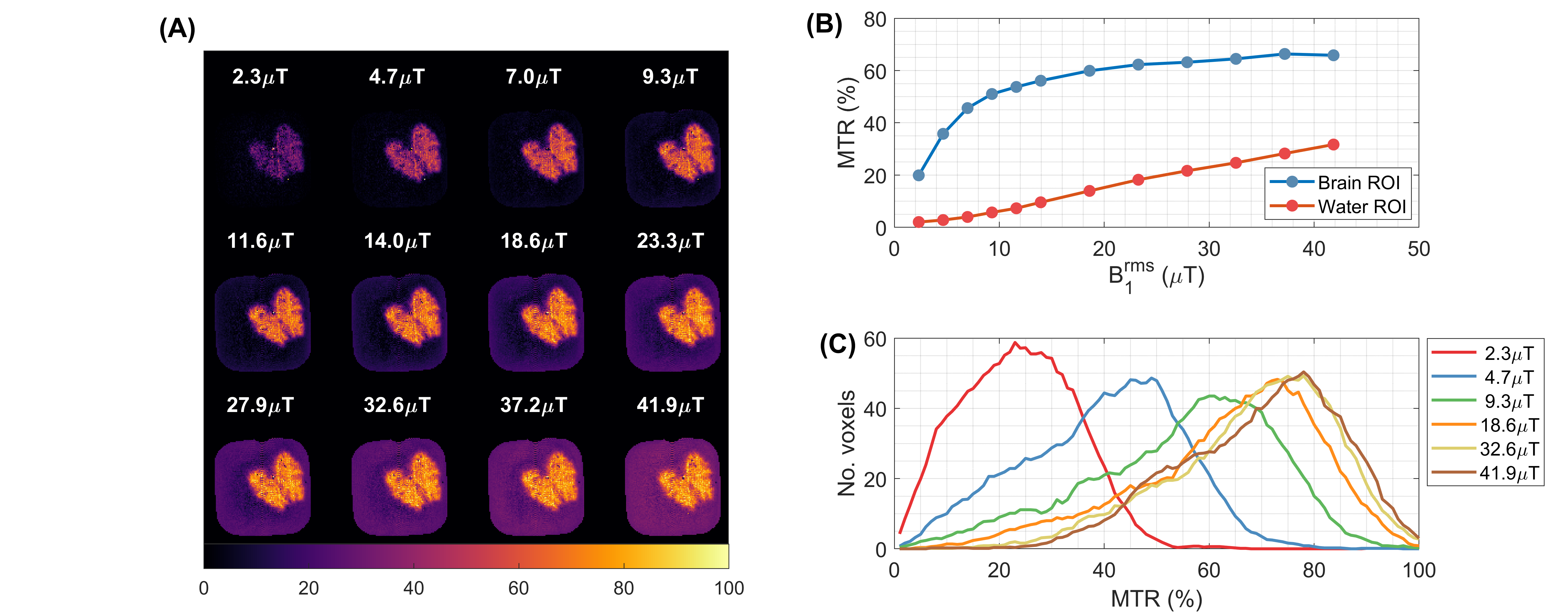
A second experiment used GRE to avoid complications from the BS shift. Figure 5 illustrates strong MTR with the effect plateauing at $$$\approx{}20\mu{}T$$$. Around the maximum B1rms of the body transmit coil (without the resonator) of $$$\approx{}4\mu{}T$$$ the MTR is $$$\approx{}30\%$$$ , whereas with the resonator at $$$20\mu{}T$$$ the MTR increases to $$$80\%$$$. We also observe a direct saturation effect in the water, possibly exacerbated by a high gadolinium concentration that led to $$$T_2^*\approx{}25ms$$$ in the water.
Conclusions
The resonator boosted the transmit B1 field up to 9-fold, yielding significantly enhanced MTR and ihMTR contrasts (boosted from 30% to 80% and 3% to 9%, respectively). This is an effective way to generate novel contrasts on low field MR systems. We aim to design a resonator that would be safe for in vivo use at 0.55T. At very high B1 levels the RF pulses designed for lower B1 are no longer effective, and so alternative RF design strategies tailored to high B1 are the subject of ongoing research.Acknowledgements
The research was supported by core funding from the Wellcome/EPSRC Centre for Medical Engineering [WT203148/Z/16/Z] and by the National Institute for Health Research (NIHR) Biomedical Research Centre based at Guy's and St Thomas' NHS Foundation Trust and King's College London and/or the NIHR Clinical Research Facility. The views expressed are those of the author(s) and not necessarily those of the NHS, the NIHR or the Department of Health and Social Care.References
(1) Shchelokova A V., van den Berg CAT, Dobrykh DA, et al. Volumetric wireless coil based on periodically coupled split-loop resonators for clinical wrist imaging. Magn Reson Med. 2018;80(4):1726-1737. doi:10.1002/mrm.27140
(2) Malik SJ, Teixeira RPAG, West DJ, Wood TC, Hajnal J V. Steady-state imaging with inhomogeneous magnetization transfer contrast using multiband radiofrequency pulses. Magn. Reson. Med. 2019 doi: 10.1002/mrm.27984.
(3) Yarnykh VL. Actual flip-angle imaging in the pulsed steady state: A method for rapid three-dimensional mapping of the transmitted radiofrequency field. Magn Reson Med. 2007;57(1):192-200. doi:10.1002/mrm.21120
Figures