0946
Safe Spirals for Your Scanner1Electrical Engineering, Stanford University, Stanford, CA, United States, 2Radiology, Stanford University, Stanford, CA, United States, 3Center for Cognitive and Neurobiological Imaging, Stanford University, Stanford, CA, United States
Synopsis
Keywords: Pulse Sequence Design, Pulse Sequence Design
Motivation: Vibration of gradient coils is a source of loud acoustics, signal dropout, field distortion, and potential system damage particularly at mechanical resonant frequencies.
Goal(s): To design safe spiral gradient waveforms which avoid mechanical resonant frequencies and their resulting severe vibrations.
Approach: Instantaneous gradient frequency during spiral readout is estimated as the rotational frequency of a circle at the current k-space radius and gradient amplitude. Amplitude is limited to drop through resonant bands quickly. A convex problem for spiral rewinders is formed minimizing the DFT at resonant frequencies.
Results: Coil vibration was significantly reduced using safe spirals, and gradient field oscillations were minimized.
Impact: Frequency constrained “safe” spiral waveforms were shown to avoid specified frequency bands, reducing gradient vibrations and k-space oscillations without degrading image quality. Such waveforms could potentially prolong gradient coil lifetime, reduce acoustic discomfort, and remove artefacts from persisting k-space oscillations.
INTRODUCTION
Rapid switching of gradient fields in MRI results in large Lorentz forces on the gradient coils. Such forces cause displacement and deformation of the coils and can result in long-lasting vibration. These vibrations can result in loud acoustic waves, signal dropout, field distortion, and in severe cases delamination of the coils1–4. Vibrations can be particularly strong if they are induced at mechanical resonant frequencies in the coils. For this reason, system vendors frequently include “lockout echo spacings” in EPI sequences to avoid repetitive switching at a mechanical resonant frequency. However, spiral trajectories pose a more difficult problem as they typically sweep through a range of frequencies which can include the mechanical resonances of the gradient coil. Furthermore, gradient rewinders from the end of the trajectory may also excite mechanical resonance. While methods exist for designing spirals that are band-limited5, mechanical resonances can occupy narrowband regions within the frequency range generally used for spiral acquisitions. Here we have developed methods for safe spirals and their rewinders which avoid specified frequency bands without detriment to image quality.METHODS
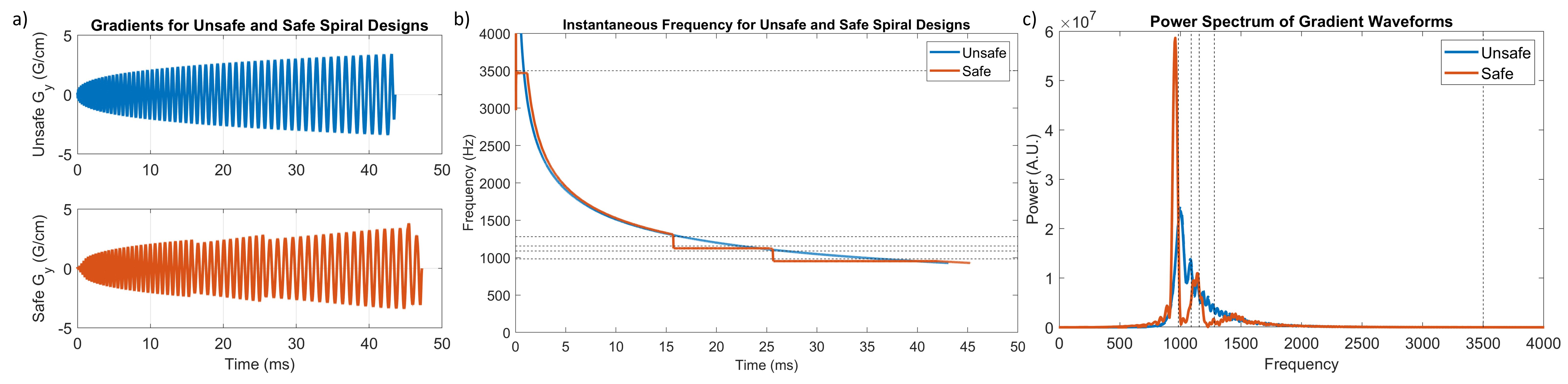
The instantaneous gradient frequency during readout is approximated as the rotational frequency of tracing a circle with the current k-space radius and gradient amplitude.$$f(t)\approx|G(t)|/2{\pi}k_r(t)$$
To design a safe spiral which avoids desired frequency stopbands, we iteratively calculate time-optimal spiral-out gradients6 while updating the maximum allowed gradient amplitude to rapidly drop the instantaneous frequency below stopbands as we enter them. When all stopbands have been iterated over from highest to lowest, the final spiral is produced as shown in Figure 1. A rewinder is then designed which avoids the same stopbands. This can be achieved by solving a convex problem where the objective minimizes the DFT of the gradient waveform at frequencies of interest.
$$\begin{aligned}\underset{{\bf{g}}\in{\Bbb{R}}^{N}}{minimize}\quad&\Vert{}D_{sin}\tilde{\bf{g}}\Vert_{2}+\Vert{}D_{cos}\tilde{\bf{g}}\Vert_{2}\qquad\qquad\quad\>\>\>\,\mathrm{DFT\>objective}\\subject\>to\quad&\Vert{\bf{g}}\Vert_{2}\leq\mathrm{100mT/m}\qquad\qquad\qquad\quad\>\mathrm{maximum\>amplitude}\\&\Vert{\bf{g}}_{i+1}-{\bf{g}}_{i}\Vert_{2}\leq\mathit{dt}\cdot\mathrm{200T/m}\cdot\mathrm{s}\qquad\mathrm{maximum\>slewrate}\\&{\bf{g}}_{n}=\mathrm{0mT/m}\qquad\qquad\qquad\qquad\quad\,\mathrm{end\>boundary\>condition}\\&\frac{\gamma}{2\pi}dt\sum_{i=1}^N{\bf{g}}_{i}=\Delta{\bf{k}}\qquad\qquad\qquad\quad\,\mathrm{k-space\>displacement}\\&|H_{hp}{\bf{g}}|\leq\epsilon\qquad\qquad\qquad\qquad\qquad\>\,\mathrm{bandlimiting\>constraint}\end{aligned}$$
Here, the matrices $$$D_{sin}$$$ and $$$D_{cos}$$$ are the real and imaginary components of the DFT at the frequencies of interest, $$$\bf{g}$$$ is the rewinder we are designing, and $$$\tilde{\bf{g}}$$$ is the rewinder padded by the preceding spiral.
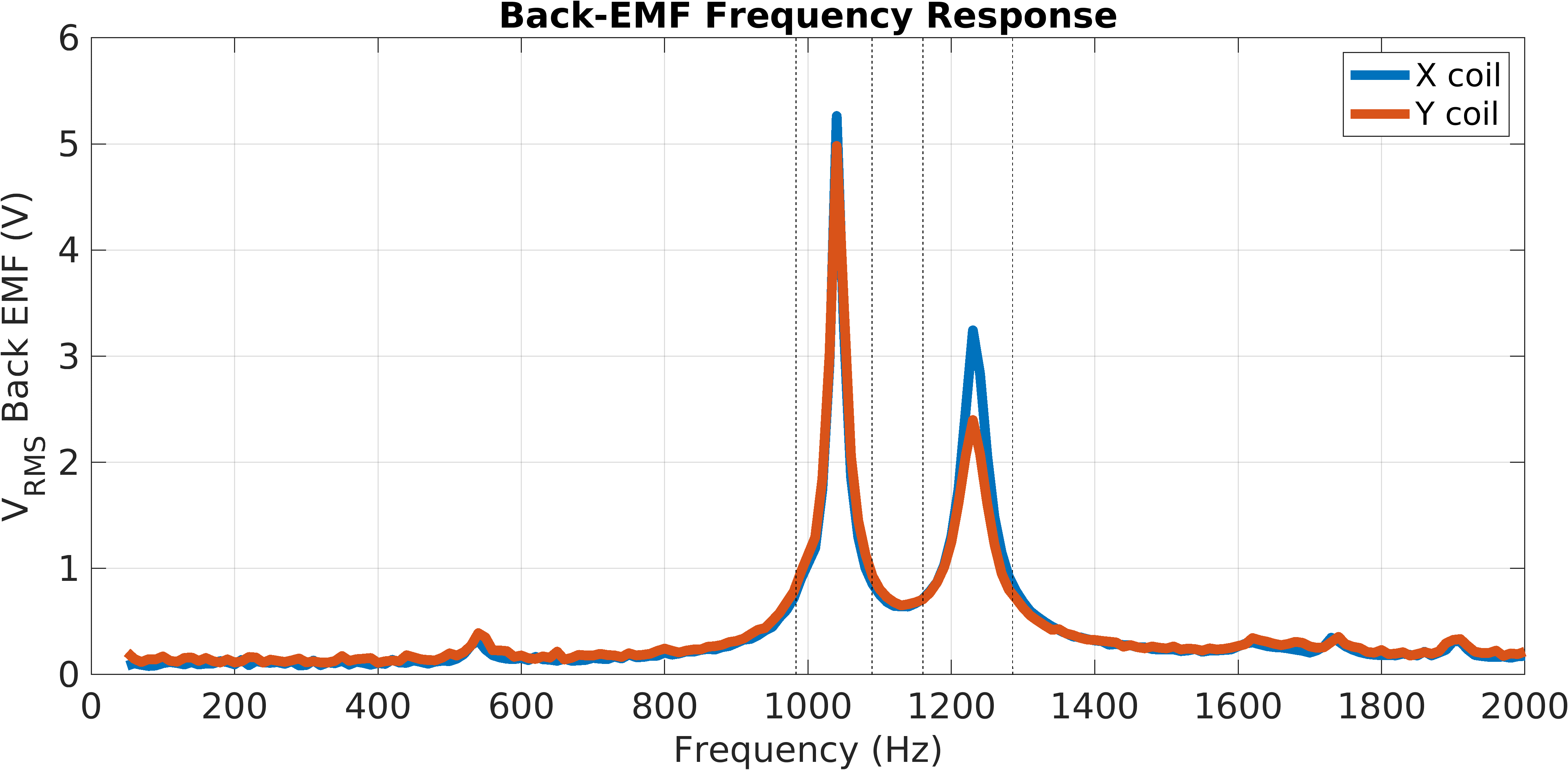
The bridge voltage of a current-controlled gradient power amplifier (GPA) is measured following the application of test gradient waveforms. Vibration of the coil induces an EMF that the GPA will buck to maintain the desired zero current, meaning the bridge voltage (or back-EMF) acts as an indicator of vibration magnitude. The back-EMF is measured for 20ms following each test including sinusoids from 50-2000Hz, a time-optimal spiral design, and a safe spiral design each with a resolution of 2mm and FOV of 24cm. K-space trajectory measurements over this period are taken simultaneously using a field camera (Dynamic Field Camera, Skope, Switzerland). A proof-of-concept b=0s/mm2 T2 weighted image is also taken with time-optimal and safe spirals to a resolution of 1mm and FOV of 22cm accelerated to R=2.
RESULTS
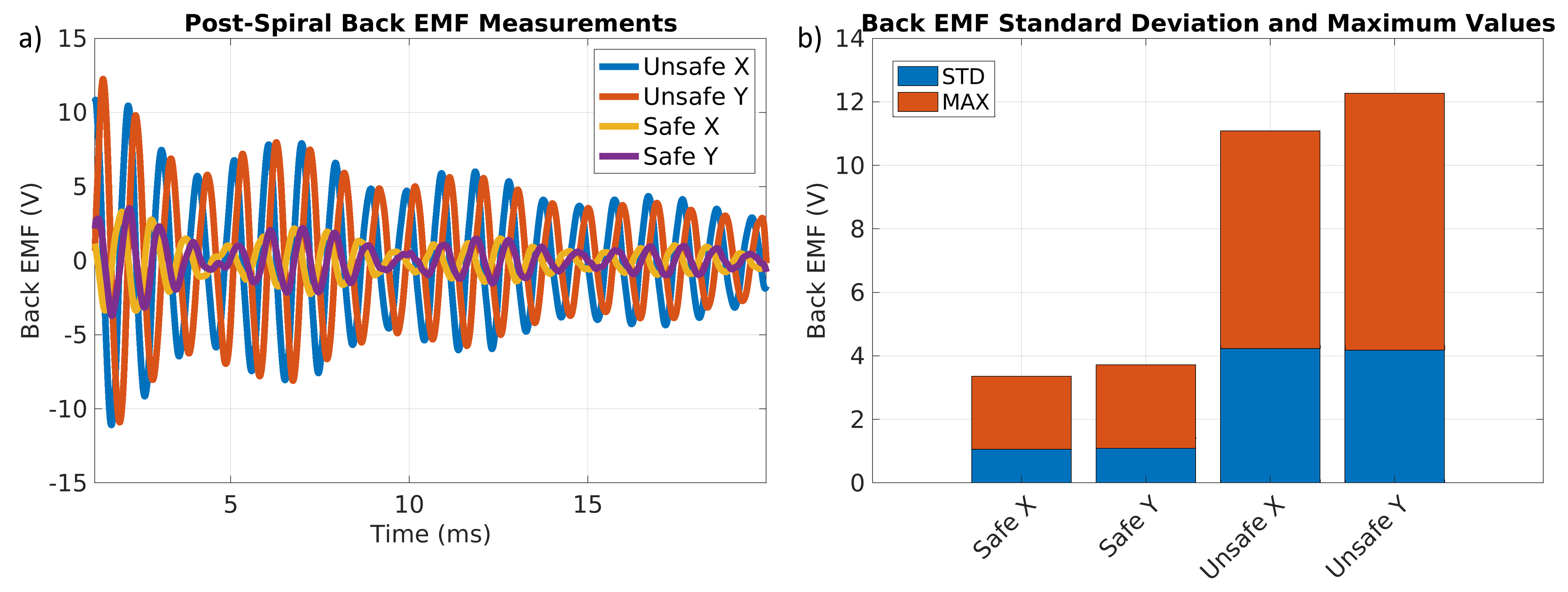
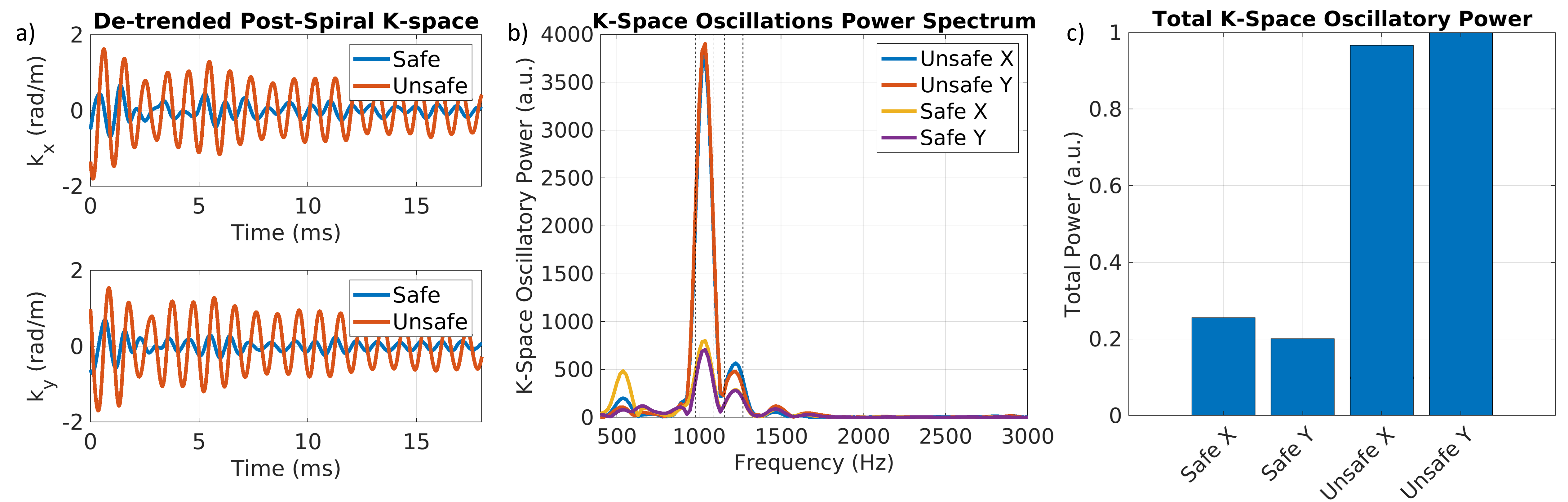
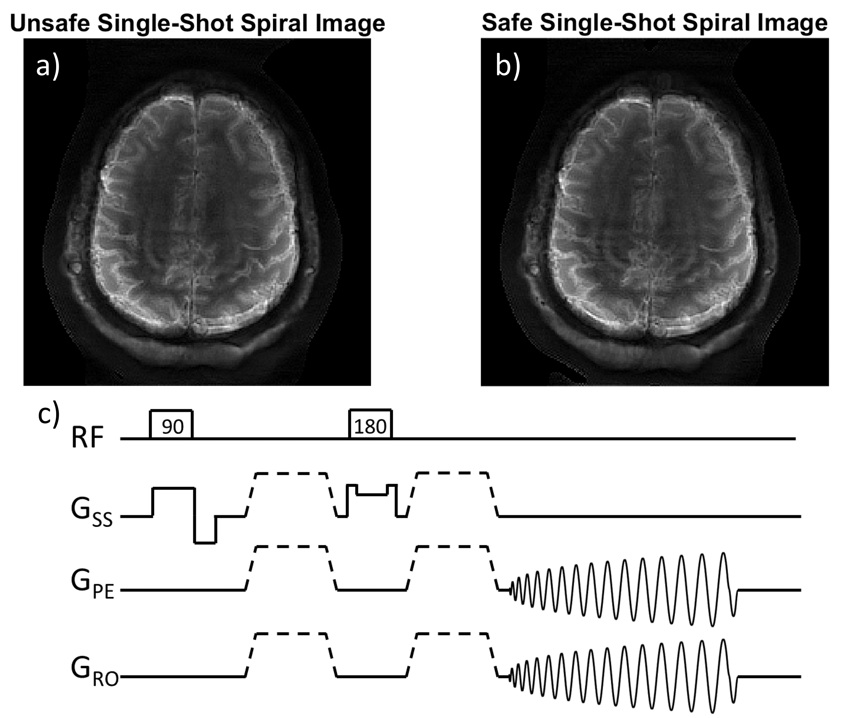
RMS measurements of the back-EMF for sinusoids from 50-2000Hz are shown in Figure 1. Figure 2 shows the design process for a safe spiral waveform. Back-EMF measurements for the time-optimal and safe spirals are given in Figure 3. Concurrent k-space measurements are analyzed in Figure 4. Figure 5 compares the results of in vivo imaging with a time-optimal and safe spiral.DISCUSSION
We can see from Figure 1 that strong mechanical resonances exist in the X and Y coils centered at 1040Hz and 1230Hz. Stopbands were centered at these points for design of safe spirals. Comparison of the time-optimal and safe spirals confirms that the safe spiral design dramatically reduces the back-EMF (Figure 3) and therefore vibration of the coils. We can see from the Skope camera measurements (Figure 4) that vibration of the coils leads to persistent k-space oscillation long after the spiral is complete. The authors posit that these oscillations are not a contribution of eddy currents, but of the back-EMF induced in the coils as they vibrate in the main B0 field. These vibrationally-induced fields are significantly reduced by the safe spiral design. The proof-of-concept image shows no noticeable artifact for adopting the safe spiral trajectory. However, other FOV and resolution prescriptions that have greater spectral energy in the mechanical resonance bands for the unsafe spiral still need to be investigated to see if there may also be some improvement in image quality for the safe spiral design.CONCLUSION
Here we have outlined a method for reducing mechanical vibration of gradient coils during spiral imaging. The safe spiral designs were shown to reduce vibration-related back-EMFs, and vibrationally-induced k-space artifacts. Preliminary image testing showed no loss of image quality with the new designs.Acknowledgements
This work was supported by the National Institutes of Health under grants R01EB009690 and U01EB029427.
We acknowledge the support of the Natural Sciences and Engineering Research Council of Canada (NSERC) through the Postgraduate Scholarship - Doctoral Program (PGSD).
Nous remercions le Conseil de recherches en sciences naturelles et en génie du Canada (CRSNG) de son soutien.
References
1. McNulty JP, McNulty S. Acoustic noise in magnetic resonance imaging: An ongoing issue. Radiography. 2009;15(4):320-326. doi:10.1016/j.radi.2009.01.001
2. Berl MM, Walker L, Modi P, et al. Investigation of vibration-induced artifact in clinical diffusion-weighted imaging of pediatric subjects. Hum Brain Mapp. 2015;36(12):4745-4757. doi:10.1002/hbm.22846
3. Gallichan D, Scholz J, Bartsch A, Behrens TE, Robson MD, Miller KL. Addressing a systematic vibration artifact in diffusion-weighted MRI. Hum Brain Mapp. 2010;31(2):193-202. doi:10.1002/hbm.20856
4. Winkler SA, Schmitt F, Landes H, et al. Gradient and shim technologies for ultra high field MRI. Neuroimage. 2018;168:59-70. doi:10.1016/j.neuroimage.2016.11.033
5. Pipe JG, Borup DD. Generating spiral gradient waveforms with a compact frequency spectrum. Magn Reson Med. 2022;87(2):791-799. doi:10.1002/mrm.28993
6. Lustig M, Kim SJ, Pauly JM. A fast method for designing time-optimal gradient waveforms for arbitrary k-space trajectories. IEEE Trans Med Imaging. 2008;27(6):866-873. doi:10.1109/TMI.2008.922699
Figures