0909
Design, construction and first experimental results of the high performance LH7 insertable head gradient set at 10.5T1Radiology, Stanford University, Stanford, CA, United States, 2CMRR, University of Minnesota, Minneapolis, MN, United States, 3Robarts Research Institute, University of Western Ontario, London, ON, Canada, 4Stanford University, Stanford, CA, United States, 5Roemer Consulting, Lutz, FL, United States
Synopsis
Keywords: Gradients, Gradients, ultra high field, insertable head gradient, PNS
Motivation: Increased gradient performance can address several of technical and physics challenges of UHF MRI.
Goal(s): To develop a head gradient coil (known as LH7) for insertion into the body gradient coil of a 10.5T MRI system.
Approach: Design innovations include: symmetric folded geometry with variable end-flange angle optimized for shoulder geometry; double Z-primary layer.
Results: With 650A, 2000V gradient drivers, the hardware limits of LH7 are Gmax 117mT/m and Smax 900T/m/s. Thermal results demonstrate cooling capacity >45kW. Compared to body gradients, PNS thresholds are 2-3 fold higher. After interfacing LH7 to the CMRR 10.5T, promising experimental characterizations and imaging results have been obtained.
Impact: LH7 provides an order-of-magnitude increase in head gradient performance (Gmax*Smax) over body gradients, which, combined with 10.5T B0, should provide major sensitivity and resolution increases for brain mapping by dMRI or fMRI. Experimental results to date are confirming these expectations.
Introduction
Widespread adoption of UHF MRI is limited by technological and physics challenges that have resulted in sub-optimal imaging performance1,2; these factors include faster signal decay, greater field inhomogeneities and high / inhomogeneous power deposition. Increased gradient performance can address several of these problems, by decreasing echo times and echo spacings and more generally by increasing encoding efficiency. To this end, we have developed an innovative insertable gradient coil, known as “large head gradient generation7” (LH7), specifically designed for insertion into the Siemens SC72 body gradient coil and to increase the neuroimaging performance of an existing UHF magnet – the 10.5T at CMRR.Methods
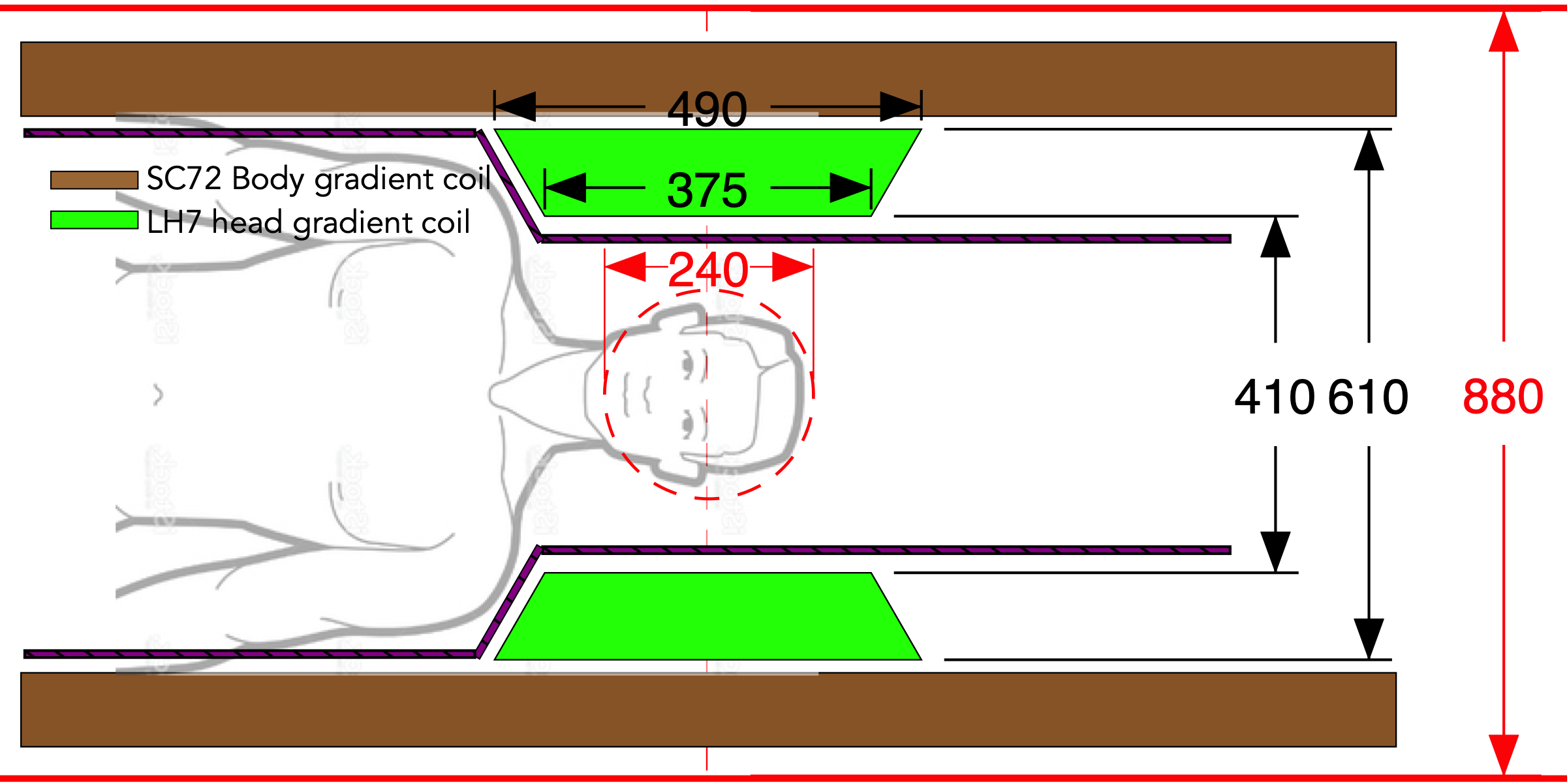
LH7 design innovations include: symmetric folded geometry with variable end flange angle optimized for shoulder geometry, double Z-primary layer, and all hollow copper conductors.Figure 1 shows the LH7 concept, with dimensions designed to meet the requirements of whole-brain imaging as an SC72-insertable head gradient. We set the following design targets: gain (sensitivity) ≥180µT/m/A and inductance ≤420µH. These targets would produce Gmax 117mT/m at 650A and Smax 900T/m/s at 2000V which correspond to 1.7-fold higher gradient strength and 4.5-fold higher slew rate compared to the SC72 body gradient.
The design of LH7 employed a quadratic optimization approach to yield minimum inductance subject to a set of equality and inequality constraints on gradient strength, concomitant fields, linearity and uniformity errors, eddy currents, peak current density, and net force and torque.
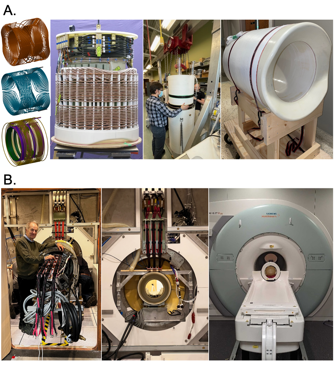
The construction of LH7 employed 3D printed rungs and end-flanges to support and position the hollow copper conductors. Coolant flowing through each hollow copper axis was split across four parallel sub-circuits to improve the total flow rate and cooling capacity. The completed coil was vacuum-potted using thermally-conductive epoxy. Figure 2A illustrates several stages of construction leading to the completed gradient coil.
LH7 was installed into the Siemens SC72 gradient, supported by a 12.5mm thick Sylodyn NB grid, and connected to the Siemens gradient power amplifiers with quad-twisting gradient cables for maximum Lorentz force cancellation. A custom bore-liner provided acoustic and vibration isolation between head gradient and patient, while preserving compatibility with the Siemens motorized patient table and RF interface. Figure 2B shows LH7 being installed into the 10.5T magnet at CMRR.
We characterized the following quantities by modeling and measurement: peripheral nerve stimulation thresholds, thermal (cooling) performance, surface vibrations, acoustics, spatial distortion, and imaging performance.
Results
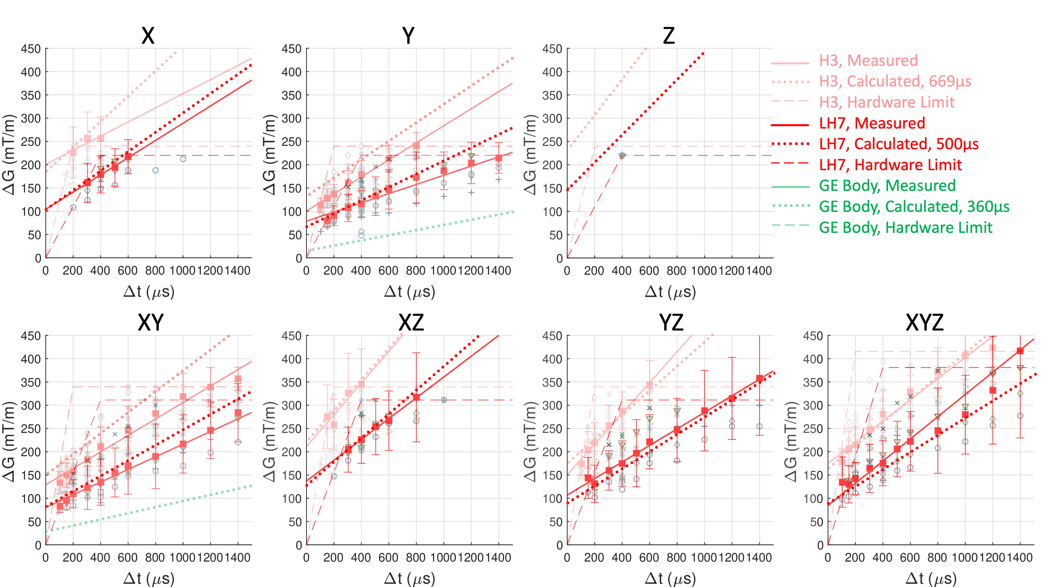
Figure 3 shows the measured and Emax-predicted PNS thresholds for LH7 in comparison to those from the H3 head gradient and a GE body gradient3. The Emax-predicted PNS thresholds (dotted) are within ~15% of with the measured thresholds (solid). PNS thresholds for LH7 are substantially higher (2-3 fold) than those of the body gradient but not as high (approximately 2/3) as those of H3. Note that the linearity region diameter of H3 (~19-22cm) is smaller than that of LH7 (24cm), which likely explains the PNS difference.Thermal calculations and measurements show that the total cooling capacity of LH7 exceeds 40kW. This very high thermal performance is the result of the direct contact between coolant and hollow copper inner surface, as well as the 4-way parallel flow circuit design. During high duty cycle imaging, interior temperatures (sampled by thermistors at 8 different points located near anticipated hot spots) never exceeded 50°C.
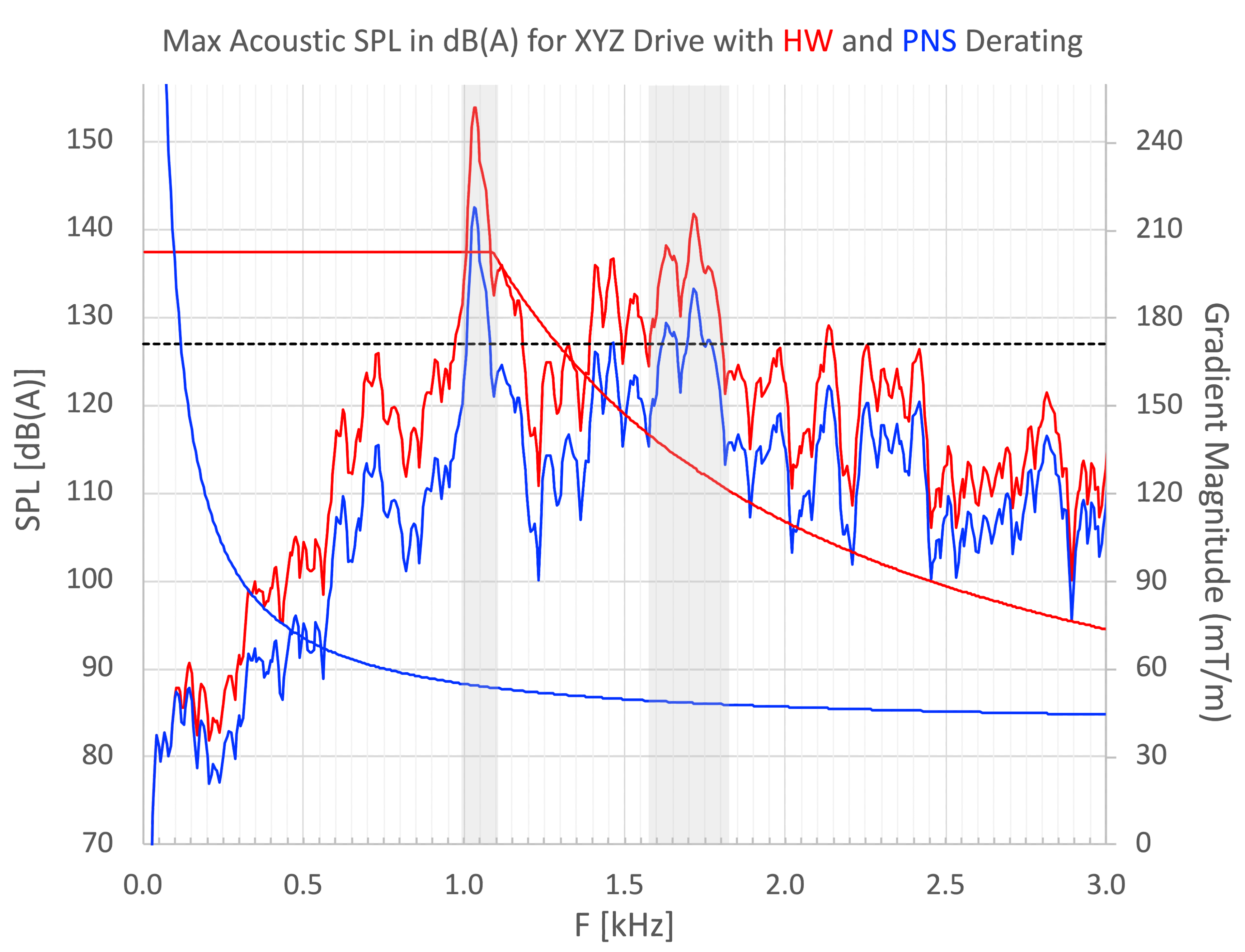
Calibrated acoustic measurements were made while driving X, Y, and Z axes simultaneously, with low amplitude (1mT/m) sinusoidal waveforms whose frequency was swept from 0 to 3 kHz. Measured acoustic sound pressure levels were then scaled to system maximum amplitude (set by hardware and PNS limits). Figure 4 plots these maximum SPL spectra for simultaneous XYZ drive, with hardware-only limited case shown in red and PNS-limited case shown in blue. The horizontal dashed line indicates a safety limit of 127 dB(A). The PNS-limited acoustic levels exceed this safety limit over three narrow frequency ranges: 1-1.08, 1.62-1.66 and 1.7-1.75 kHz. Prior to any further acoustic mitigation strategies, these frequency bands will need to be locked out in system configuration.
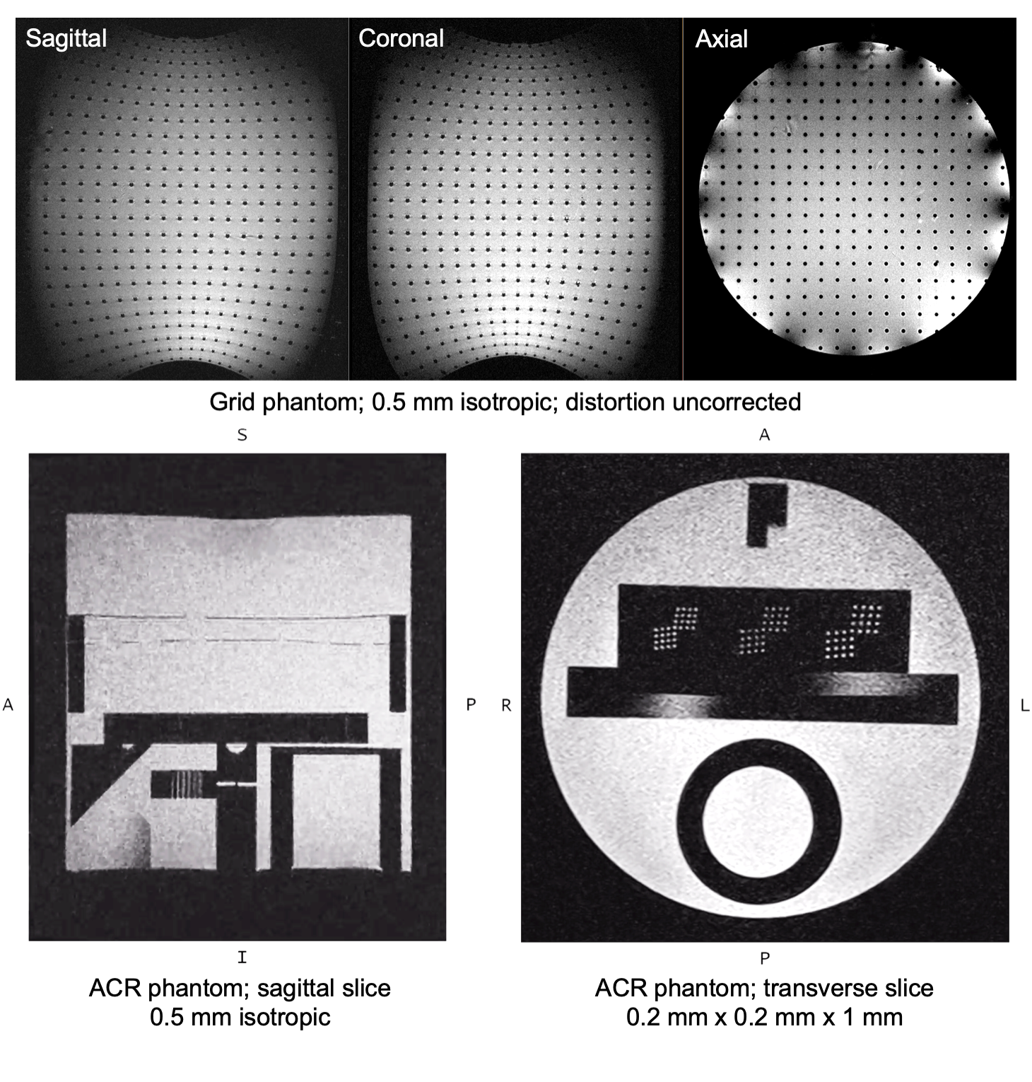
Figure 5 shows first phantom images made with LH7 at 10.5T. Grid phantom images show the expected spatial distortions over a cylinder of 18cm diameter by 22cm length. ACR phantom images show high spatial resolution with minimal artifact.
Discussion and Conclusion
We have designed, built and characterized the LH7 head gradient coil at 10.5T. First experimental results confirm design and modeling expectations of high gradient strength / slew rate and excellent PNS and thermal performance. PNS-limited acoustic levels are within safety limits outside of three narrow frequency ranges. We are currently developing mitigation strategies to further reduce acoustic levels.Acknowledgements
The authors gratefully acknowledge research support from NIH U01 EB025144 and NIH R01 EB025131. We also acknowledge support from the Sim4Science program at ZurichMedTech.References
1. Winkler, S.A., Alejski, A., Wade, T., McKenzie, C.A. & Rutt, B.K. On the accurate analysis of vibroacoustics in head insert gradient coils. Magn Reson Med (2016).
2. Moser, E., Stahlberg, F., Ladd, M.E. & Trattnig, S. 7-T MR--from research to clinical applications? NMR Biomed 25, 695-716 (2012).
3. Roemer, P.B., Wade, T., Alejski, A., McKenzie, C.A. & Rutt, B.K. Electric field calculation and peripheral nerve stimulation prediction for head and body gradient coils. Magn Reson Med 86, 2301-2315 (2021).
Figures