0788
MRI-conditional deep brain stimulation (DBS) implants: a new engineered design for enhanced safety1Radiology, Massachusetts General Hospital and Harvard Medical School, Charlestown, MA, United States, 2Northwestern University, Chicago, IL, United States, 3Harvard University, Cambridge, MA, United States
Synopsis
Keywords: Safety, Parkinson's Disease, Deep Brain Stimulation
Motivation: Currently, patients with Deep Brain stimulation (DBS) implants cannot leverage the diagnostic potential of Magnetic Resonance Imaging (MRI) as traditional metal-based leads pose several safety concerns.
Goal(s): We propose a new technology for manufacturing DBS microwires that ensures their safe operation with MRI up to 3T.
Approach: Through the development of a metamaterial-based design, we have engineered microwires that effectively partially reflect RF-induced current, thereby reducing Specific Absorption Rate (SAR), tip heating, and associated artifacts.
Results: Our manufactured microwires demonstrated minimal tip heating in both 1.5T and 3T MRI scanners when compared to standard wires.
Impact: This innovative design facilitates safe MRI imaging for individuals with DBS implants, marking a pivotal advancement in the study of neural mechanisms involved in medically refractory pathological conditions, such as Parkinson’s disease.
Introduction
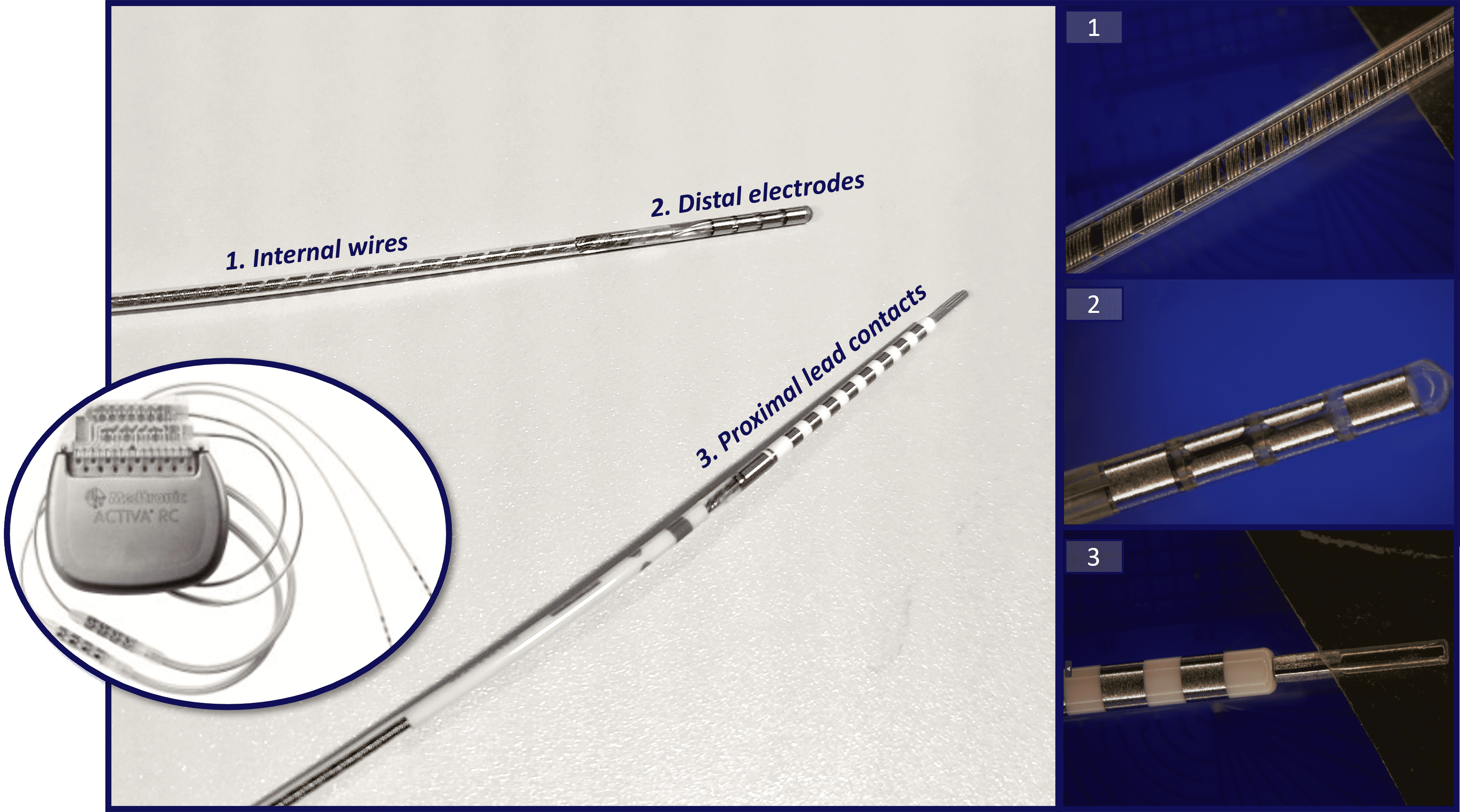
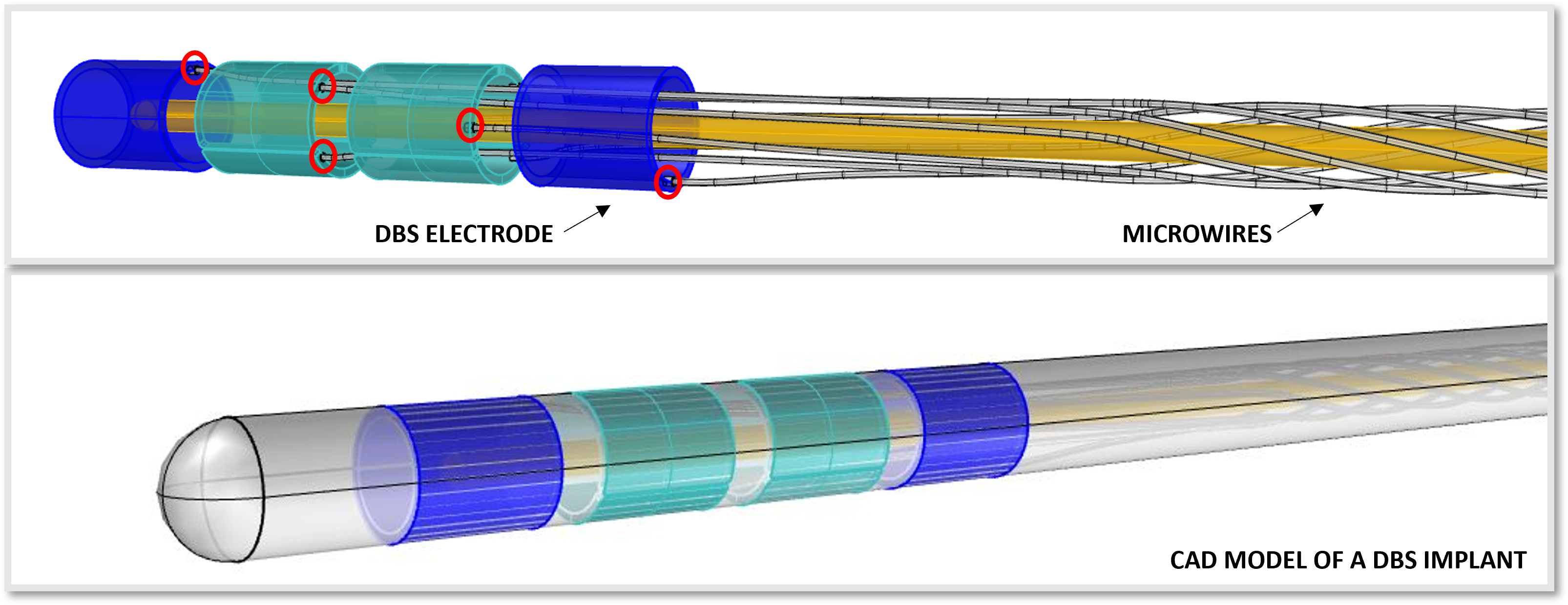
Deep Brain Stimulation (DBS) is a surgical procedure used for the long-term treatment of movement disorders1,2, such as Parkinson’s disease, dystonia, and other pathological conditions, like medical refractory epilepsy. It involves the delivery of electrical pulses to specific brain regions responsible for these medical conditions. This is achieved through implanted electrodes connected to an implantable pulse generator (IPG) via an extension lead containing inner Platinum-Iridium microwires routed beneath the skin (Fig. 1). In modern DBS leads, the stimulation can be highly precise and selective, thanks to directional electrodes capable of both horizontal and vertical steering currents3. However, one significant limitation is their poor compatibility with magnetic resonance imaging (MRI). Indeed, under the influence of a strong magnetic field, the metal wires can behave as an antenna, resulting in excessive heating of the electrodes at the tip, thus posing a risk of heat-related injuries to the patient. To address this issue, the development of MRI-safe DBS leads is essential4. Our research focuses on designing an innovative metamaterial-based technology for manufacturing the internal microwires of DBS leads, ensuring their safe operation during MRI scans up to 3T5.Methods
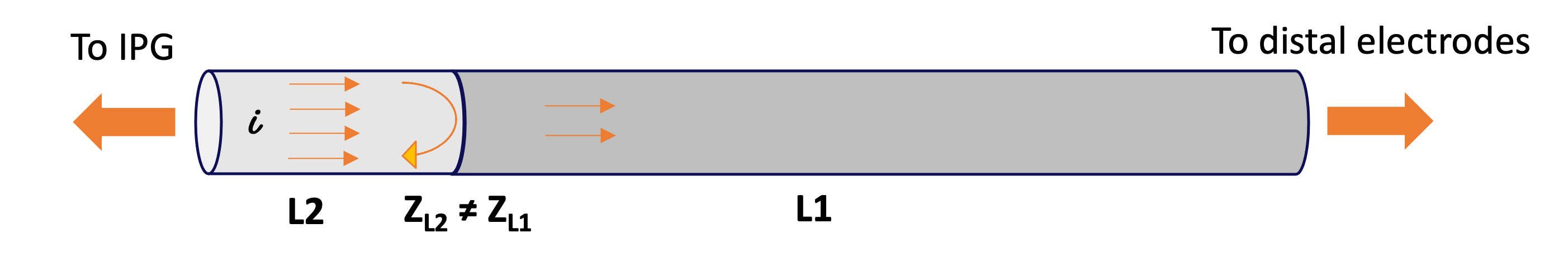
The proposed technology involves the layering of two metal segments (L1, L2) with distinct impedance on a substrate microwire. Importantly, the abrupt change in impedance at the metal interface between the two segments can disrupt radiofrequency (RF)-induced currents traveling from the IPG to the electrodes at the implant's tip (Fig. 2), thereby reducing electrode heating, specific absorption rate (SAR), and MRI artifacts5. The properties of the microwires, such as length and conductivity of the two metal segments, were optimized through numerical simulations using Ansys HFSS software, by minimizing the 0.1g SAR at the tip of the implant as a function of L2 segment length and for varied conductivity ratios σ12 between segments. The target resistance of the wire was selected based on compatibility with IPG voltage range to keep the generated current under the safety limits. As a substrate for the microwire fabrication, we selected a cylindrical non-conductive and non-magnetic wire made of a composite biocompatible material, with a diameter of 500μm and a length of 40cm. The two metal segments were then layered onto this substrate using the e-beam physical vapor deposition technique at the Harvard Center for Nanoscale Systems. Gold was chosen as the deposition metal due to its outstanding electrical and magnetic properties, along with its proven safety for use in brain implants. Finally, wire insulation and protection against environmental degradation was obtained by parylene conformal coating, a biocompatible thin film polymer. Both the engineered microwire and a uniform all-gold control wire were tested for tip heating in both 1.5T and 3T MRI scanners using a gel-like phantom to mimic human tissue characteristics. Temperature probes were wrapped around the wire ends to monitor variations.Results
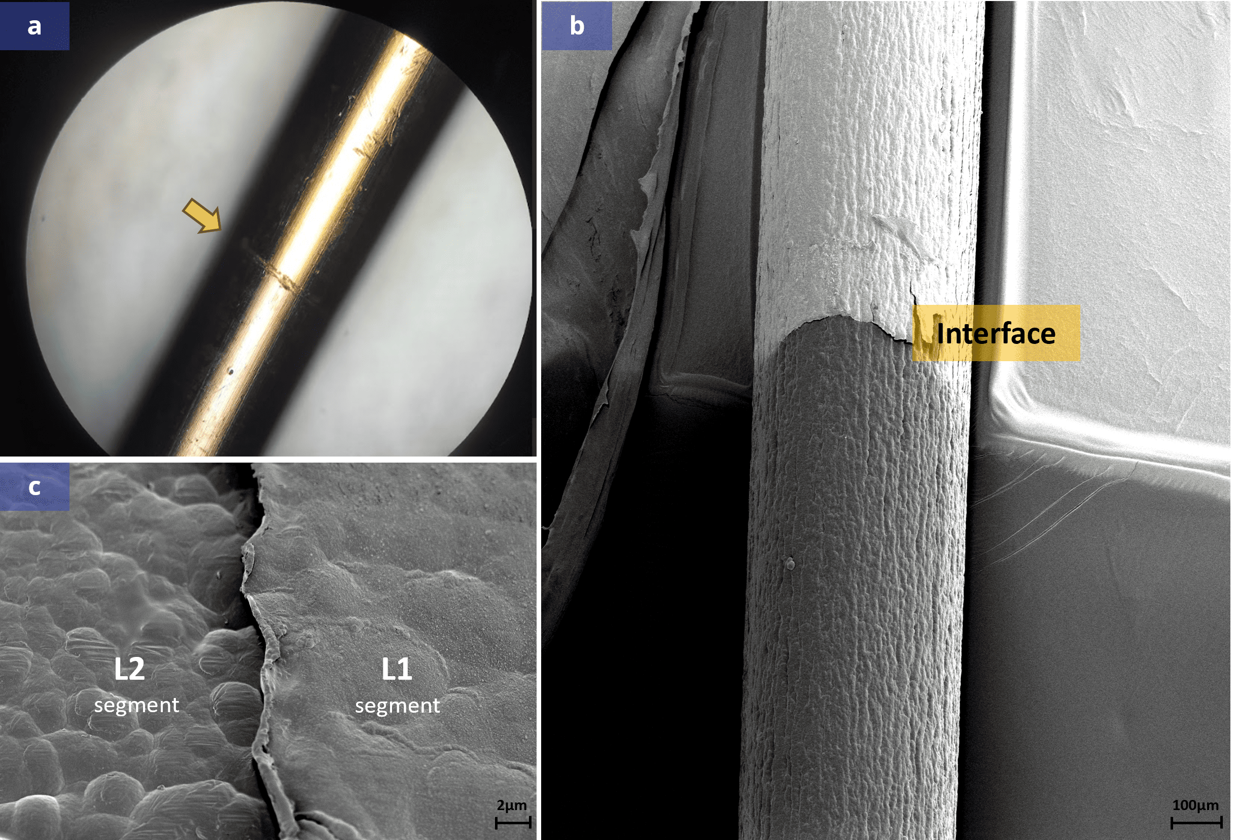
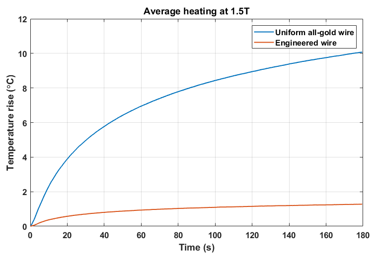
Based on simulation results, the optimal design for significantly reducing the SAR involved the layering of two metal segments with a conductivity ratio σ12 greater than 10 and lengths of L1=25 cm and L2=15 cm. For a theoretical R of about 400Ω and a σ12=18, we deposited 40nm of gold on the shorter segment, L2, and about 700 nm on the longer one, L1 (Fig. 3). A thin layer of titanium was inserted beneath the gold layer to improve adhesion to the substrate material. The measured resistance of the fabricated microwire exceeded the theoretical value by approximately 100Ω, which may be attributed to the intrinsic resistivity of the material used and other environmental factors. Nevertheless, this variation was within the acceptable range. Heating test results were very promising: the fabricated microwire exhibited a temperature increase of less than 2°C both at 1.5T and 3T; in contrast, the control all-gold wire heated up to 10°C under the same conditions (Fig. 4).Discussion
Given the extensive use of DBS implantable devices in treating various chronic brain-related disorders, the demand for MRI-safe devices has surged. Simultaneously, the need for biocompatibility and compactness presents significant challenges. Our innovative metamaterial-based approach transforms the internal microwires of conventional DBS leads, rendering them MRI-compatible through a simple design. Despite the promising outcomes of our technology, there remain hurdles to overcome, mainly centered on further reducing the overall size of the wires to 80-100μm and their assembling, to ensure flexibility and strength (Fig. 4), before proceeding with biocompatibility and efficacy tests.Conslusion
The technology we propose for manufacturing DBS microwires effectively addresses current MRI-compatibility limitation, opening up exciting possibilities for investigating the dynamics of the brain associated with movement disorders and other challenging neurological conditions with functional MRI.Acknowledgements
This project was funded by the National Institutes of Health (R01 Research Grant Nr. 5R01NS128962-02).References
1. Miocinovic S, Somayajula S, Chitnis S, Vitek JL. History, Applications, and Mechanisms of Deep Brain Stimulation. JAMA Neurol. 2013;70(2):163–171.
2. Schroeder KE, Chestek CA. Intracortical Brain-Machine Interfaces Advance Sensorimotor Neuroscience. Front Neurosci. 2016 Jun 28;10:291.
3. Steigerwald F, Matthies C, Volkmann J. Directional Deep Brain Stimulation. Neurotherapeutics. 2019 Jan;16(1):100-104.
4. Boutet A, Chow CT, Narang K, Elias GJB, Neudorfer C, Germann J, Ranjan M, Loh A, Martin AJ, Kucharczyk W, Steele CJ, Hancu I, Rezai AR, Lozano AM. Improving Safety of MRI in Patients with Deep Brain Stimulation Devices. Radiology. 2020 Aug;296(2):250-262.
5. Serano P, Angelone L M, Katnani H, Eskandar E, Bonmassar G. A Novel Brain Stimulation Technology Provides Compatibility with MRI. Scientific Reports. 2015 Apr;9805(5).
Figures