0786
Built-in RF safety for active implants: Harnessing impedance measurements from a commercial deep brain stimulator1Physikalisch-Technische Bundesanstalt (PTB), Braunschweig and Berlin, Germany, 2Chair of Microwave Engineering, Christian-Albrechts-Universität zu Kiel, Kiel, Germany
Synopsis
Keywords: Safety, Safety, Deep brain stimulation, Active implantable medical devices, RF safety
Motivation: MRI of neurostimulators is severely constrained due to RF safety concerns.
Goal(s): Demonstrate that built-in sensors in commercial devices, such as a deep brain stimulator, can provide all necessary information to detect and improve RF safety.
Approach: We investigated and utilized built-in impedance measurements of two commercial DBS systems for the detection and mitigation of RF-induced currents on the electrodes of a DBS lead.
Results: Impedance measurements were correlated at various RF power levels. Temperature rise at the tip of DBS electrodes could be reduced to 0.02 K from 17.14 K at the same total powers (16.85±0.45 W).
Impact: Our demonstration of mitigation of RF-induced heating in active implants through built-in sensor measurements from a commercial DBS system indicated up to ~850× improvement in temperature rise proving the unmet value of sensors for MR imaging patients with active implants.
Introduction
RF heating significantly constrains MRI accessibility for patients with implants like Deep Brain Stimulators (DBS). Devices that can be scanned safely are bound to operational restrictions, which pose severe limitations e.g., SAR≤0.2W/kg.1 Sensors on the implant can detect the RF heating threat2–6 and wirelessly transmit this information,6,7, which subsequently can be used to substantially suppress tip SAR and temperature e.g., by parallel transmission (pTx) techniques. It was even shown that the sensor information alone can even be utilized to maintain imaging quality under acceptable RF heating conditions.5,7,8 A limitation of these studies was the use of self-built implant hardware, sensor-readout circuits and leads, questioning transferability of those results to real-life implants with tightly integrated electronic circuits. In this work, we demonstrate, for the first time, how the built-in features of an off-the-shelf commercial DBS system are sufficient to detect and mitigate RF-induced heating without any modifications to the implant. These results strongly suggest that a smart-implant concept where the device communicates with the MRI scanner is indeed tangible, with simultaneous benefits for patient safety, diagnostic image quality, and burden on the MR operators.Methods
A commercially available DBS system (Vercise, Boston Scientific) was used together with a matching 8-channel directional electrodes (Cartesia, Boston Scientific).9RF-induced impedance change
To adjust stimulation currents, the device offers a mode, where the impedances between all electrodes and the implantable pulse generator (IPG) are measured and wirelessly transmitted to the programming device (Figure-1).10 We hypothesized that any RF-induced currents on the lead must affect these measurements resulting in altered impedance readings by the device. This hypothesis was investigated in phantom experiments by using a realistically placed MR conditional DBS system (Figure-1).11 An 8-channel pTx RF coil was placed on the head of the phantom and operated by a continuous-wave pTx system5 at varying total power (0-30W).
Impedance measurements (duration≈1-2s) were performed by the DBS implant with and without simultaneous RF transmission (≈5s) and the RF-induced impedance change was calculated.
Mitigation of RF-induced heating
To not only detect but also mitigate the RF-induced currents on the implant, an ASTM phantom was used (Figure-2), as this setup allowed an easier positioning of reference probes around the implant electrodes. Two fiber-Bragg grating temperature probes (FBG-T8, imc test&measurement) and a time-domain $$$E$$$-field probe (E1TDSz, Speag) were placed at the electrodes.
The IPG (Vercise P16, Boston Scientific) was positioned next to the shoulder part of the phantom. Since the impedance values carry no phase information of the transmitted RF pulses, the sensor Q-matrix ($$$Q_s$$$) was determined, requiring 128 impedance measurements (64 reference, 64 during RF) for the 8-channel coil.8 From $$$Q_s$$$, a ‘worst-case’ (WC) and a mitigating ‘orthogonal projection’ (OP) modes were calculated.8 RF-induced $$$E$$$-field ($$$P_{rms}=40\,mW,\,t=1\,ms$$$) and temperature rises ($$$P_{rms}=16.85±0.45\,W,\,t=60\,s$$$) at the electrode were obtained using three pTx transmission modes: WC, OP and circular polarization (CP).
Results
Figure-3A exemplifies an $$$8×8$$$ impedance measurement among electrodes and from electrodes to IPG using the DBS system. Values varied between 2.2-6.3kΩ (head phantom) and 1.1-2.4kΩ (ASTM phantom). The RF-induced impedance changes correlates well with the applied RF power, as shown for one electrode pair in Figure-3B.Figure-4A displays the calculated $$$Q_s$$$ using the measured impedance changes. RF channels 1 and 6 have the strongest contributions to RF-induced tip heating. The WC and OP modes derived from $$$Q_s$$$ are depicted in Figure-4B together with the CP mode for reference. Notably, OP has similar amplitude and phases to CP, however with smaller weighting on the critical channels 1 and 6. WC, in contrast, excites these critical channels, too, to induce constructive interference of all currents.
Figure-5 shows the good match of RF-induced $$$E$$$-fields and tip temperatures for the three transmission modes. The impedance-based $$$Q_s$$$, measured using only the integral hardware of the device, could effectively predict critical pTx modes with an extremely high temperature increase (17.14K for WC) but also the mitigating OP mode causing a tip temperature increase of only 0.02K which is 100 times less than CP mode heating (1.96K).
Discussion and conclusions
It has been demonstrated that a commercial, off-the-shelf DBS implant without any modifications can be utilized with established methodology to detect and suppress RF-induced heating. It is thus possible to substantially improve RF safety of implants and simultaneously boost imaging performance if implant and MR scanner would exchange this information prior or during an MR scan. Next to implant carrying patients also the clinical personnel would benefit, since lengthy safety assessment procedures became obsolete. It is reasonable to assume that the presented methodology can be extended to different manufacturers, device models, and implant lead configurations.Acknowledgements
This work has received funding from the European Partnership on Metrology, co-financed by the European Union’s Horizon Europe Research and Innovation Programme and by the Participating States, under grant number 21NRM05 STASIS.
This work was also partially supported by the German Research Foundation (Deutsche Forschungsgemeinschaft, DFG) through the project T1 of the Collaborative Research Centre CRC 1261.
References
1. Boutet A, Chow CT, Narang K, et al. Improving Safety of MRI in Patients with Deep Brain Stimulation Devices. Radiology. 2020;296(2):250-262.
2. Venook RD, Overall WR, Shultz K, et al. Monitoring Induced Currents on Long Conductive Structures During MRI. Intl. Soc. Mag. Reson. Med. Vol 16; 2008:898.
3. Etezadi-Amoli M, Stang P, Kerr A, et al. Controlling radiofrequency-induced currents in guidewires using parallel transmit. Magn Reson Med. 2015;74(6):1790-1802.
4. Godinez F, Tomi-Tricot R, Delcey M, et al. Interventional cardiac MRI using an add-on parallel transmit MR system: In vivo experience in sheep. Magn Reson Med. 2021;86(6):3360-3372.
5. Winter L, Silemek B, Petzold J, et al. Parallel transmission medical implant safety testbed: Real-time mitigation of RF induced tip heating using time-domain E-field sensors. Magn Reson Med. 2020;84(6):3468-3484.
6. Silemek B, Acikel V, Oto C, et al. A temperature sensor implant for active implantable medical devices for in vivo subacute heating tests under MRI. Magn Reson Med. 2018;79(5):2824-2832.
7. Silemek B, Seifert F, Petzold J, et al. Wirelessly interfacing sensor-equipped implants and MR scanners for improved safety and imaging. Magn Reson Med. 2023;90(6):2608-2626.
8. Silemek B, Seifert F, Petzold J, et al. Rapid safety assessment and mitigation of radiofrequency induced implant heating using small root mean square sensors and the sensor matrix Qs. Magn Reson Med. 2022;87(1):509-527.
9. Steigerwald F, Matthies C, Volkmann J. Directional Deep Brain Stimulation. Neurotherapeutics. 2019;16(1):100-104.
10. DBS Product Details - Vercise Genus DBS System. Boston Scientific. Accessed November 08, 2023. https://www.bostonscientific.com/en-US/products/deep-brain-stimulation-systems/vercise-genus-dbs-system.html
11. Yalaz M, Maling N, Deuschl G, et al. MaDoPO: Magnetic Detection of Positions and Orientations of Segmented Deep Brain Stimulation Electrodes: A Radiation-Free Method Based on Magnetoencephalography. Brain Sci. 2022;12(1):86.Figures
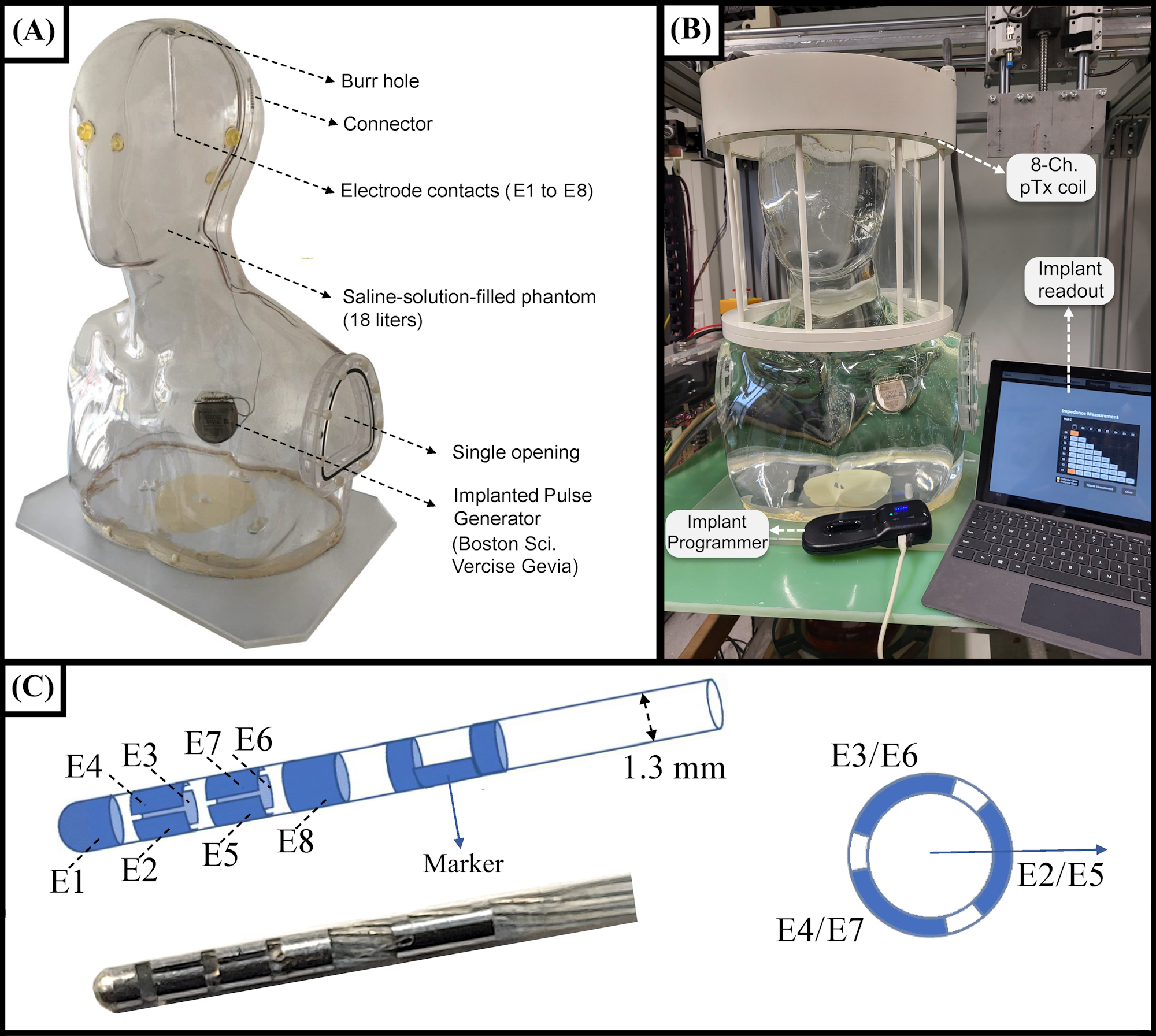
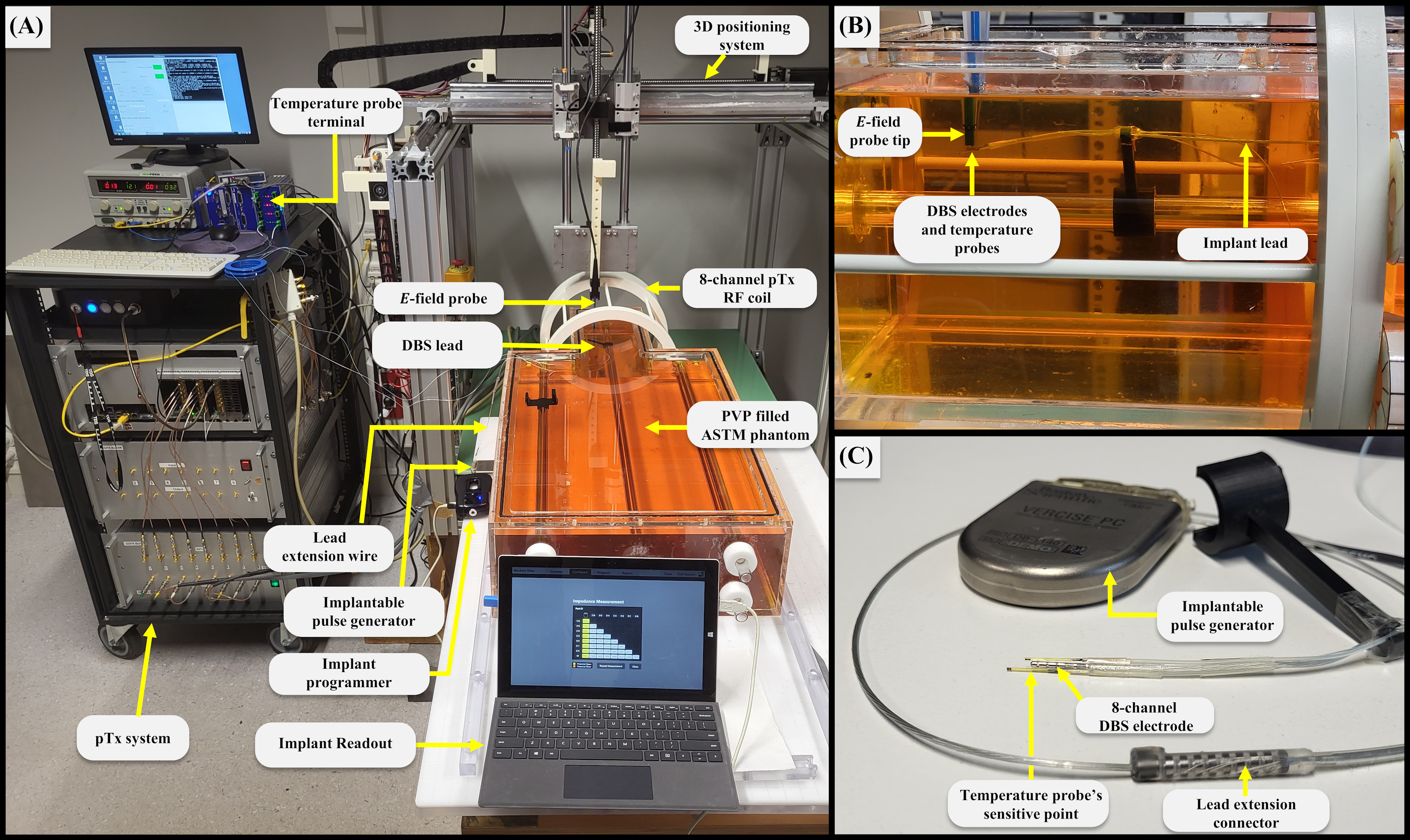
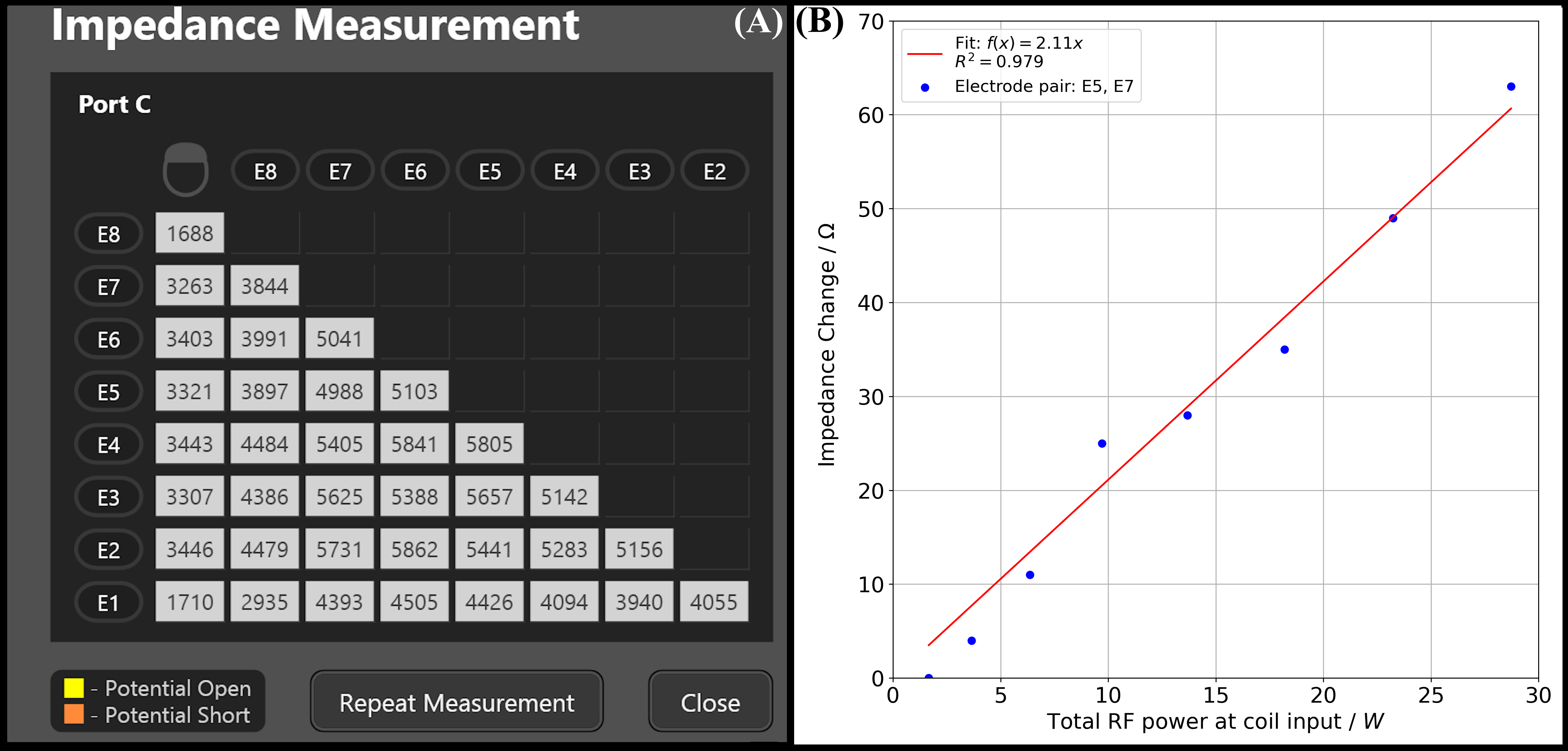
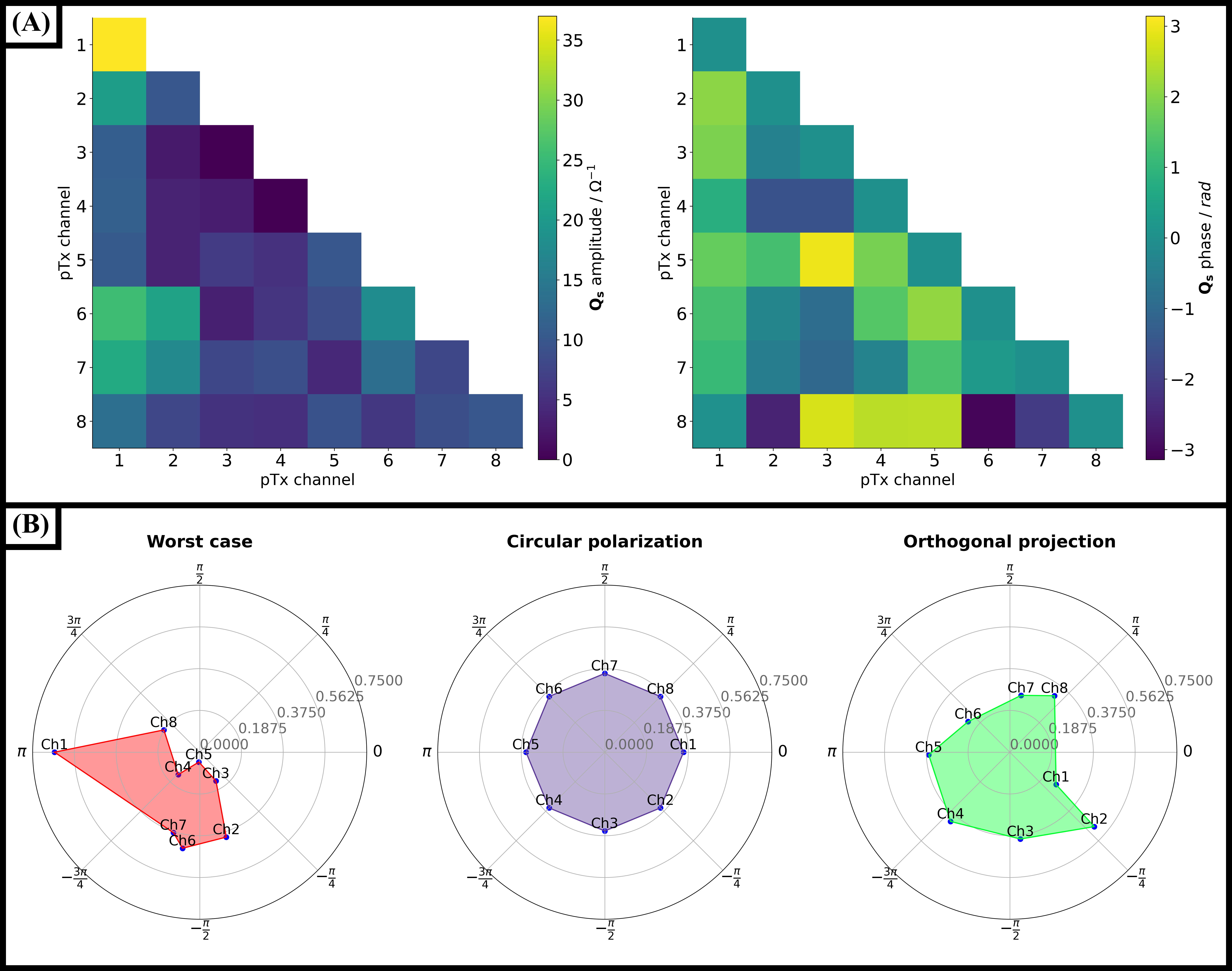
Figure 4: A) Calculated amplitude and phase of $$$Q_s$$$ from the impedance measurements. Please note that $$$Q_s$$$ is Hermitian. Channels 1 and 6 are the most relevant contributors to RF-induced heating. (B) Polar plots of the normalized pTx modes used for the mitigation experiments. OP mode amplitude and phases resembles a morphed form of the CP mode, which should mitigate RF-induced heating while preserving the imaging quality. WC mode demonstrates the combination of the dominant channels as indicated by $$$Q_s$$$.
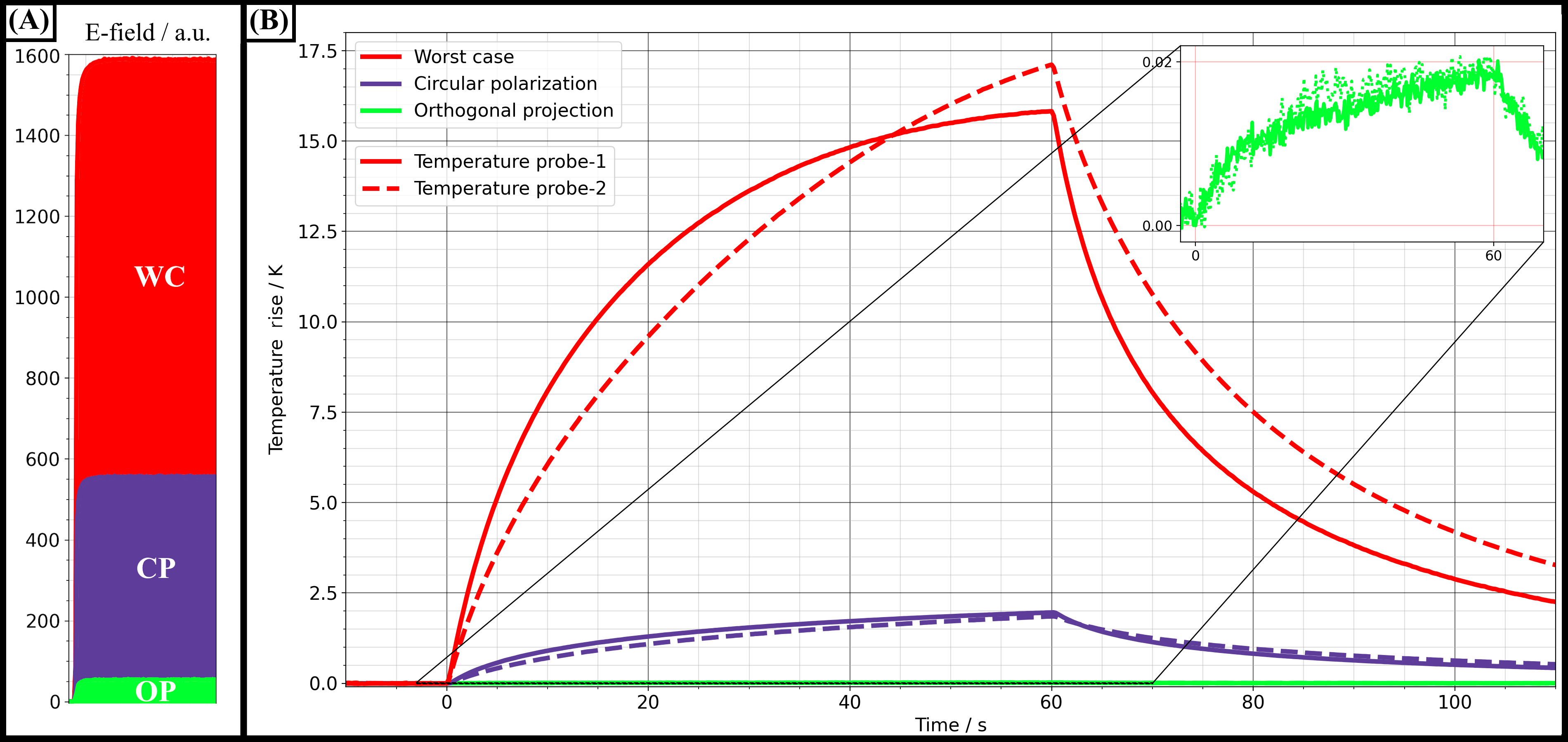
Figure 5: Results of the RF-induced heating experiments for different excitation modes. (A) Induced E-fields at the implant tip for all three pTx modes. For WC, the E-field around the tip was highest followed by CP and OP. (B) Temperature rise for a total RF transmit power of 16.85±0.45 W at three different transmission modes. OP was shown as an inlet as the implant electrodes barely heated (0.02 K) whilst WC heating generated a maximum temperature rise of 17.14 K after only one minute, CP showed a maximum of 1.96 K. OP mode could successfully reduce tip heating to maximum values around 0.02 K.