0678
Ultrahigh Resolution Imaging of Zebrafish Embryos with a µMRI Insert in a Horizontal Bore Small Animal Scanner1Ulm University, Ulm, Germany
Synopsis
Keywords: New Devices, New Devices
Motivation: The absence of hardware specifically tailored for horizontal bore small animal MRI systems hinders the achievement of ultrahigh-resolution imaging.
Goal(s): To facilitate volumetric imaging at sub 10³ µm³ spatial resolutions in a conventional horizontal small animal scanner.
Approach: A custom-made high-performance gradient system and RF-hardware was interfaced to the system RF- and gradient-amplifiers, avoiding the requirement for specialized imaging software. A constant time imaging sequence was employed to capture ultrahigh-resolution images.
Results: The setup was successfully tested for imaging of zebrafish embryos at different time points post fertilization with an isotropic spatial resolution of 9³ µm³.
Impact: The suggested approach enables isotropic single-digit µm ultrahigh resolution imaging in conventional horizontal bore MRI systems. This supports novel imaging applications for a wide range of tiny animals, plants, or biological tissue without dedicated microscopy MR systems.
Purpose
We engineered a system specifically for the imaging of diminutive samples, such as Zebrafish embryos or potentially Organoids and other tissues. This involved the design of a gradient system, an RF-coil, and a low noise amplifier (LNA) circuit, with the intention of seamless integration into an existing small animal MRI using available RF and gradient amplifiers and imaging software.Methods
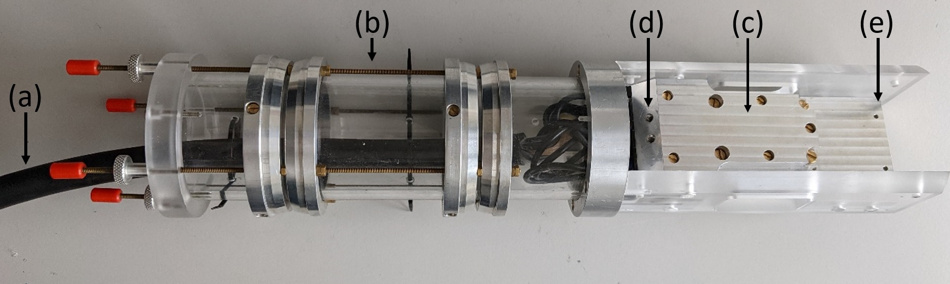
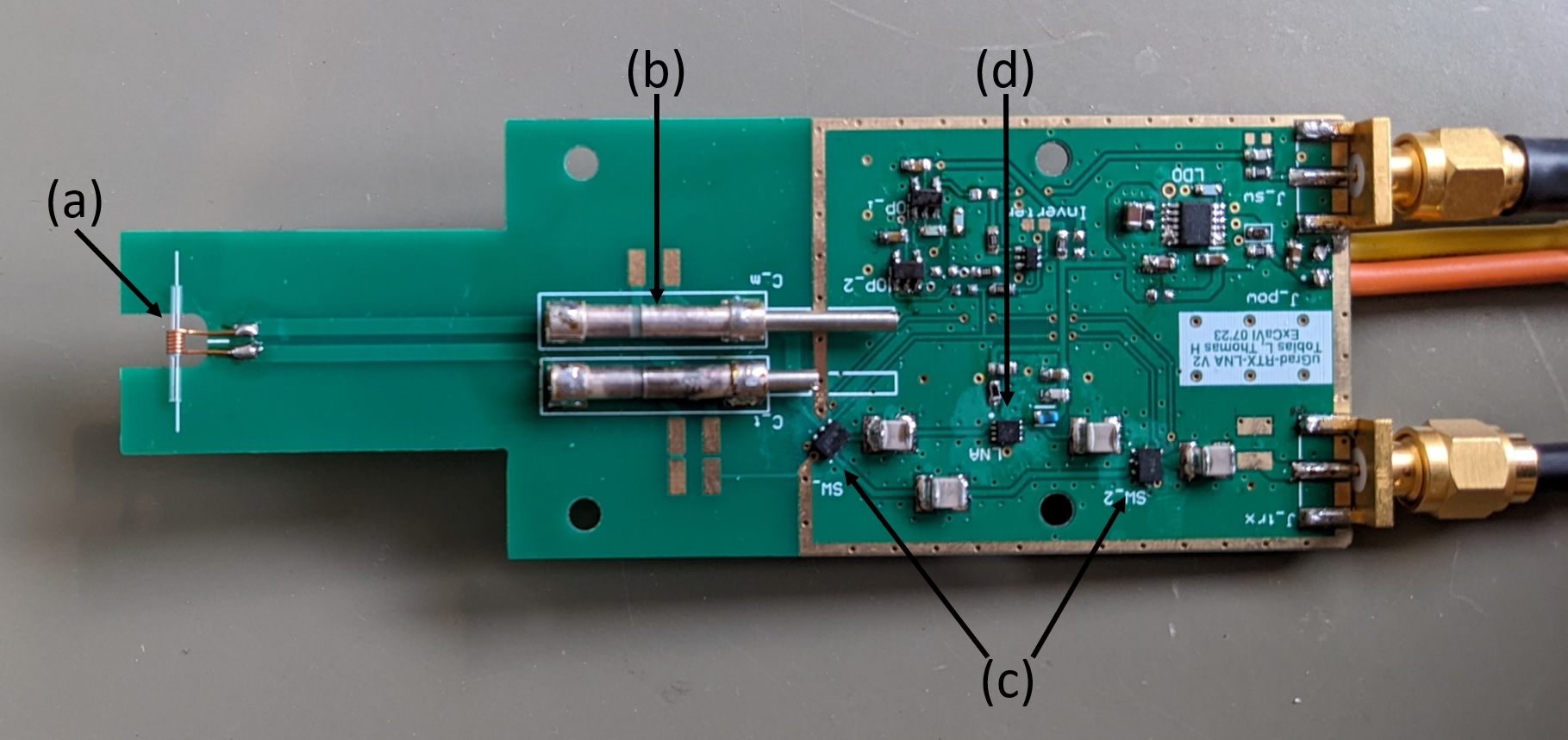
The gradient system was constructed as a biplanar system that utilizes printed circuit boards (PCB) as a foundation for high gradients in a small FOV. The conductor geometry was selected according to Weiger et al 1 and optimized for a linear region of 1x1x1 mm³ as described in ². The PCBs are adhered to an aluminum block that also provides screw holes for sample positioning and its high thermal conductivity in combination with water cooling can effectively dissipate heat induced by the gradient currents. The electrical connections of the PCBs to the gradient amplifiers of an 11.7 T small animal MRI scanner (BioSpec 117/16, Bruker Biospin, Ettlingen, Germany) are realized by using crimp-on ring terminals soldered on the PCBs and secured with screws in the aluminum block. A Bruker gradient connector enables rapid switching between the custom-built system and the ‘standard’ gradients. Temperature monitoring is realized by a Pt100, which was glued in the gradient system and can be read out in real time.For SNR considerations an additional LNA circuit was added before interfacing to the Bruker’s receive path. Two switches (VSW2‐33‐10W+, Mini‐Circuits, Brooklyn, NY, USA) use the RF blanking signal to bypass the LNA (QPL9547, Qorvo, Greensboro, NC) in the transmit case. Moreover, this PCB includes the resonant RF-circuit including the RF-coil for a sample and screw holes to enable an accurate positioning in the linear gradient field.
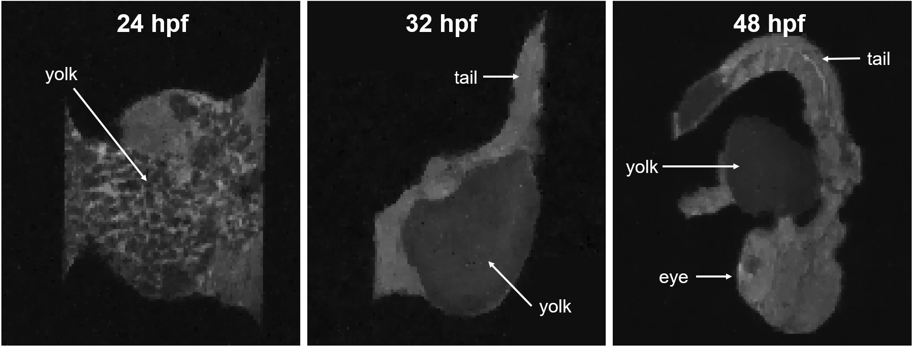
As established promising image method for ultrahigh resolution applications a constant time imaging (CTI) sequence was employed for imaging 1. Here we have used a CTI with gradient spoiling for an isotropic resolution of (9 µm) ³ with TR = 80 ms, TE = 0.8 ms, flip angle = 21° and a total scan time of 46 hours and 53 minutes.
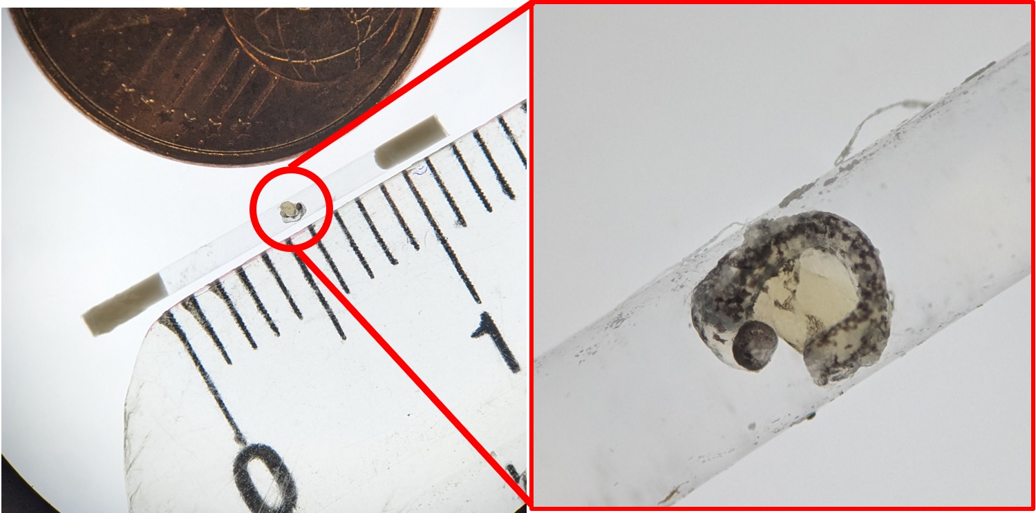
Samples of zebrafish embryos (Danio rerio) were fixated in 4 % PFA for 2 hours at room temperature at 24, 32 and 48 hours post fertilization (hpf) and transferred to glass capillaries with an inner diameter of 800 µm. The space surrounding the samples was filled with Flourinert (3 M, Maplewood, MN, USA) to minimize susceptibility artefacts. The ends of the capillary were sealed with wax to prevent the loss of any liquids.
Results
Figure 1 shows a picture of the custom-made gradient insert. The cylindrical shaped housing is used for stable fixation of the insert in the bore of the magnet. The gradient PCBs are located inside the aluminum blocks ensuring proper cooling of the gradient insert.The RF-PCB is depicted in figure 2. It incorporates the resonant circuit and switchable paths for the LNA as well as a regulated power supply and conditioning of the switching signal.
The respective samples prepared under a light microscope are shown in figure 3.
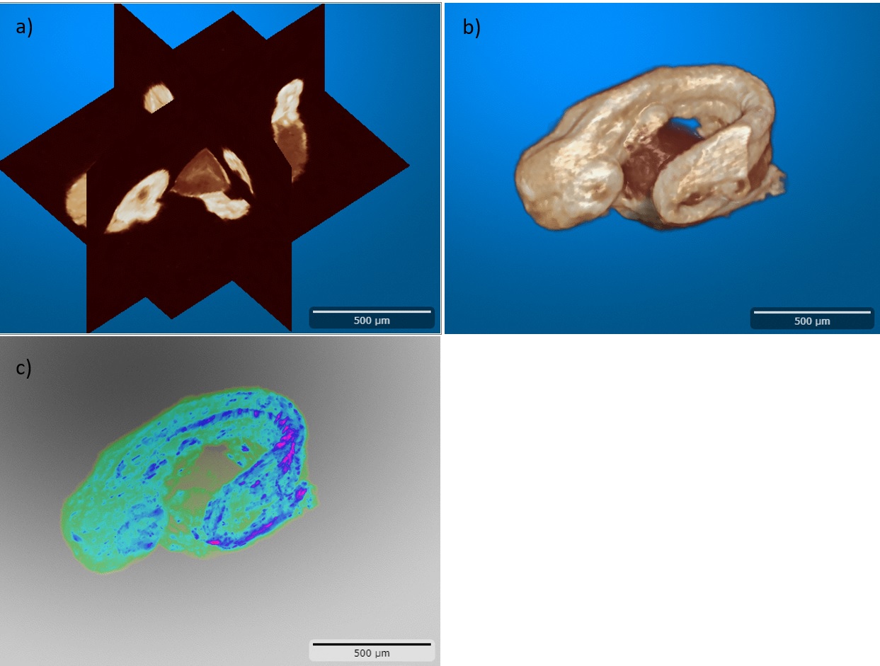
Figure 4 shows slices of the CTI data set of the three different embryos fixated 24, 32 and 48 hpf. Different anatomical regions within the embryo show a noticeable contrast difference. The MR images do not exhibit artefacts due to susceptibilities or blur because of the preparation with Flourinert and the intrinsic properties of CTI. A volume visualization is depicted in figure 5. The 48 hpf embryo reveals different details like the outer shape (b) or a fine structure trough the tail to the head (c) in the renderings created using the Image Processing Toolbox in MATLAB Release 2023b (MathWorks, Natick, MA, USA).
Conclusion
The suggested hardware could successfully be integrated in an existing system and be operated with the systems standard hard- and software. The picture of the prepared sample as shown for 48 hpf in figure 3 match well with the MR images shown in figures 4 and 5. Moreover, compared to the light microscopic image, additional features can clearly be differentiated due to the MR (sequence) specific contrasts and additionally, volumetric dimensions can be derived from the three-dimensional images. In conclusion the suggested hardware enables ultrahigh-resolution imaging in the single digit µm range at conventional MR systems.Acknowledgements
The authors thank the Ulm University Center for Translational Imaging MoMAN for its support.References
1: WEIGER, Markus, et al. NMR microscopy with isotropic resolution of 3.0 μm using dedicated hardware and optimized methods. Concepts in Magnetic Resonance Part B: Magnetic Resonance Engineering: An Educational Journal, 2008, 33. Jg., Nr. 2, S. 84-93.
2: Hüfken, Thomas Biplanar PCB based Micro-Gradient-System-Insert for a Small Animal MRI. Proc. Intl. Soc. Mag. Reson. Med. 26 (2018), 1763
Figures