0677
Four-Channel MM-Wave Radar Testbed for Neck vs Chest Cardiac Sensing1Electrical Engineering, Stanford University, Stanford, CA, United States, 2GE Healthcare, Aurora, OH, United States, 3Radiology, Stanford University, Stanford, CA, United States
Synopsis
Keywords: Hybrid & Novel Systems Technology, Hybrid & Novel Systems Technology, Radar
Motivation: Respiratory and cardiac gating are common in modern MRI, but require additional sensors in contact with the patient and the associated cabling.
Goal(s): Our goal is to determine if CW mm-wave radar can act as a robust non-contact cardiac and respiratory sensor, with potential for gating in MRI.
Approach: A 4-channel 24 GHz radar test bed is developed with a pair of neck radars and a pair of chest radars. SSA and ICA methods help extract waveform structure relative to an ECG.
Results: The CW radars nicely separate breathing and heart rate with distinct features at the ECG QRS complex.
Impact: MM-wave radar could provide a non-contact sensor of cardiac/breathing in MRI. Potential applications include non-contact gating, and independent vascular pulse or motion sensing for use in neuroimaging.
Introduction
Respiratory and cardiac gating are common requirements in MRI, and require sensors in contact with the subject. Respiratory bellows add setup time to patient workflow, and ECG is distorted by magnetohydrodynamic flow (MHD) and gradient pulses, while the leads have been implicated in RF burns. A non-contact method would be preferred. Consequently, pilot tone methods1-3 have become popular but require interoperability with the MRI signal chain. Alternatively, continuous wave (CW) Doppler radar is also non-contact and can operate independently during MRI scanning4, but cardiac sensing typically requires breath-holding. Recent work has indicated mm-wave radar can sense carotid and jugular venous pulse5 which was subsequently identified as potentially useful for MRI6. Here, we construct a 4-channel 24GHz radar testbed to assess whether neck carotid and jugular venous pulse (JVP) sensing can augment chest motion sensing of heart rate and respiration.Hardware Methods
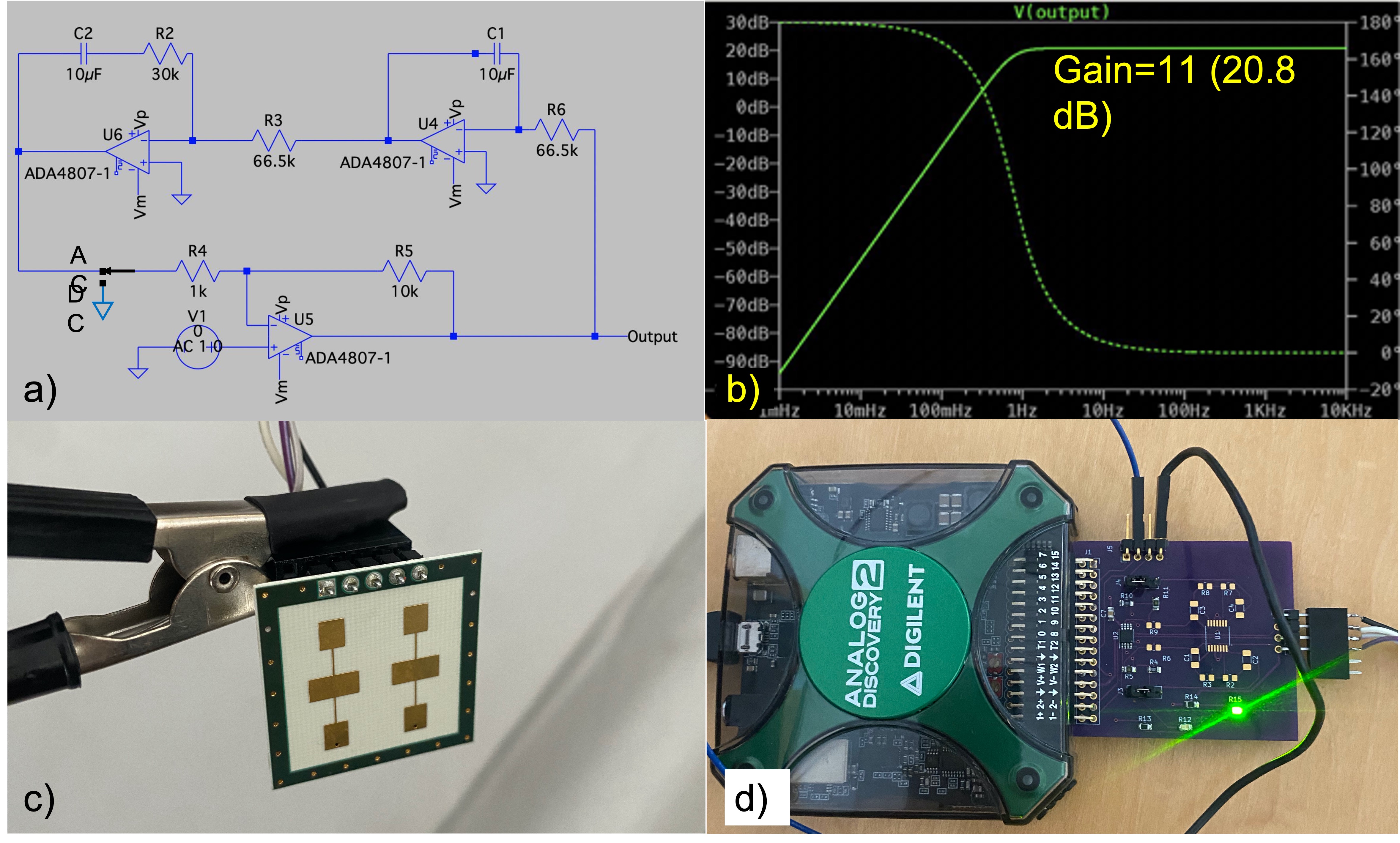
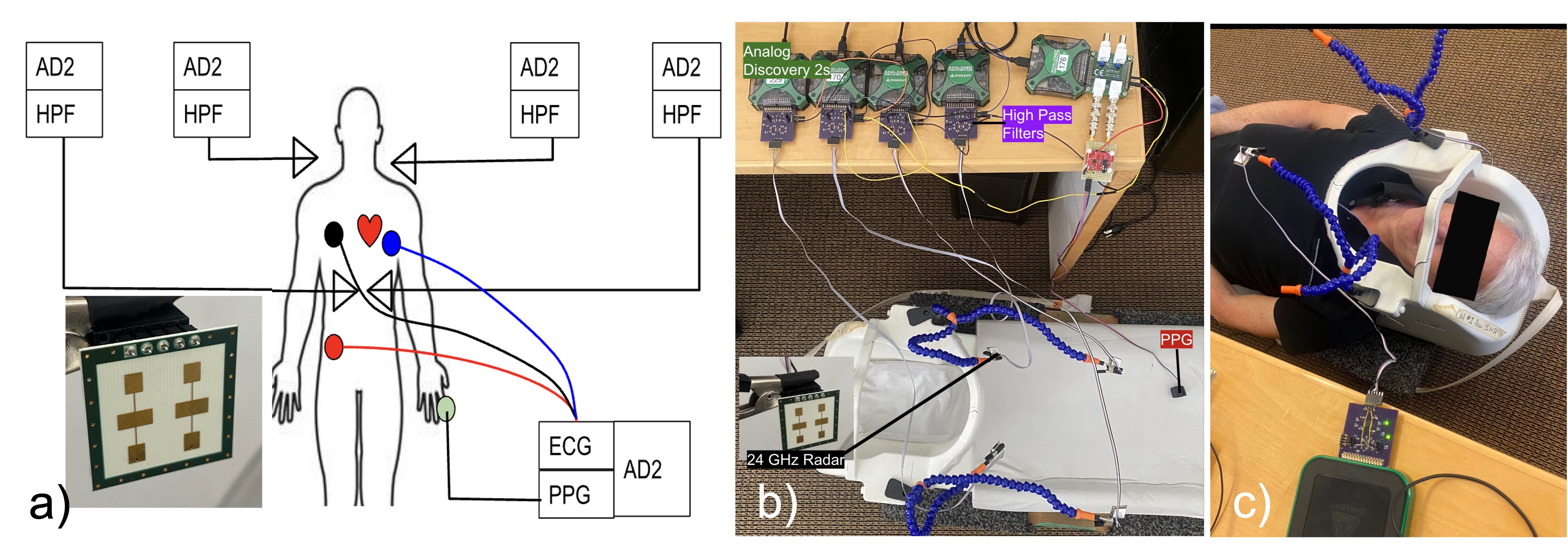
A radar test bench was constructed with four K-LC5 24GHz radar sensors (RFbeam). Custom printed circuit boards (PCB) were developed for interfacing each with Analog Discovery 2 (AD2-Digilent) digitizers. These included a 10x DC gain stage with optional 2nd order servo feedback for high pass filtering with 1Hz cutoff (Fig. 1). Two radars were placed on adjustable arms to position on the left and right sides of the neck, and a second pair placed above the left/right chest, each about 5cm above the surface. In addition, a Sparkfun ECG independently sensed cardiac signals with a fifth AD2. All used a synchronized trigger. Figure 2 shows the layout on an old MRI head coil platform.Radar Signal Processing
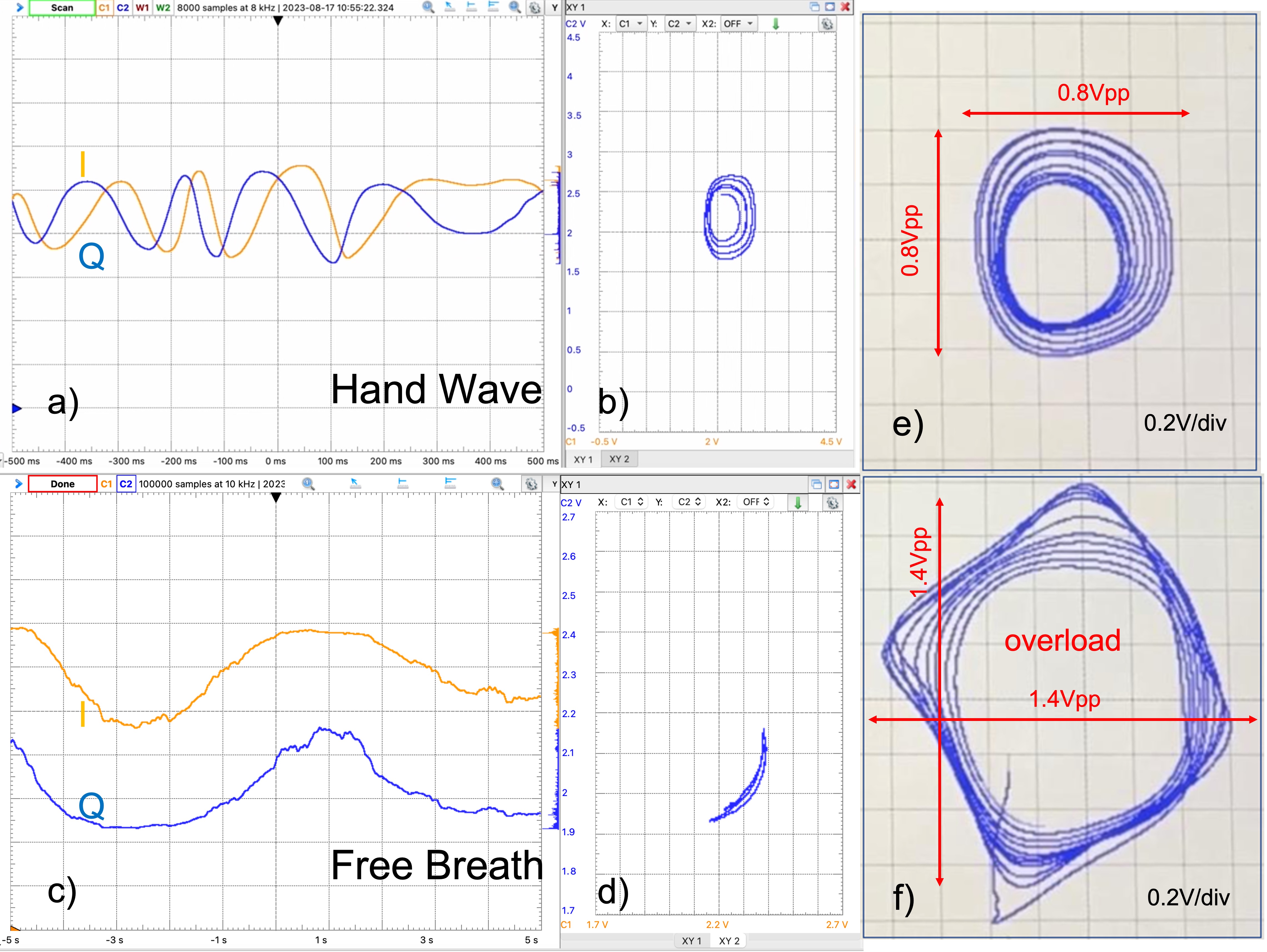
All radar and ECG data were sampled at 10kHz for 10s and subsequently decimated 100x. The complex (I&Q) signal of each radar (Fig. 3) was filtered by singular spectral analysis with window length 1/4 of the data length. The trend (first reconstructed component RC) was omitted, and data recovered from RCs 2-20. There was no explicit bandpass frequency filtering. Rather, SSA itself acted as a data-defined filter. The complex data loci were rotated with principle components extracting the dominant signals . Finally the neck pair or chest pair were applied to FASTICA to extract independent components. Aside from decimation, the ECG did not undergo further processing.Results
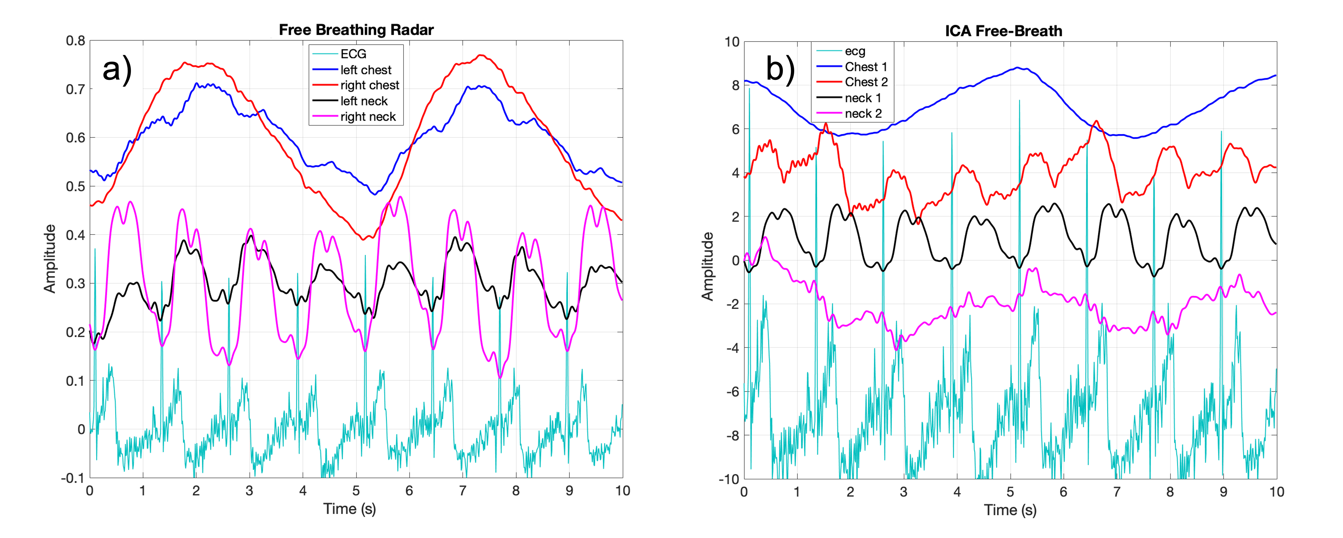
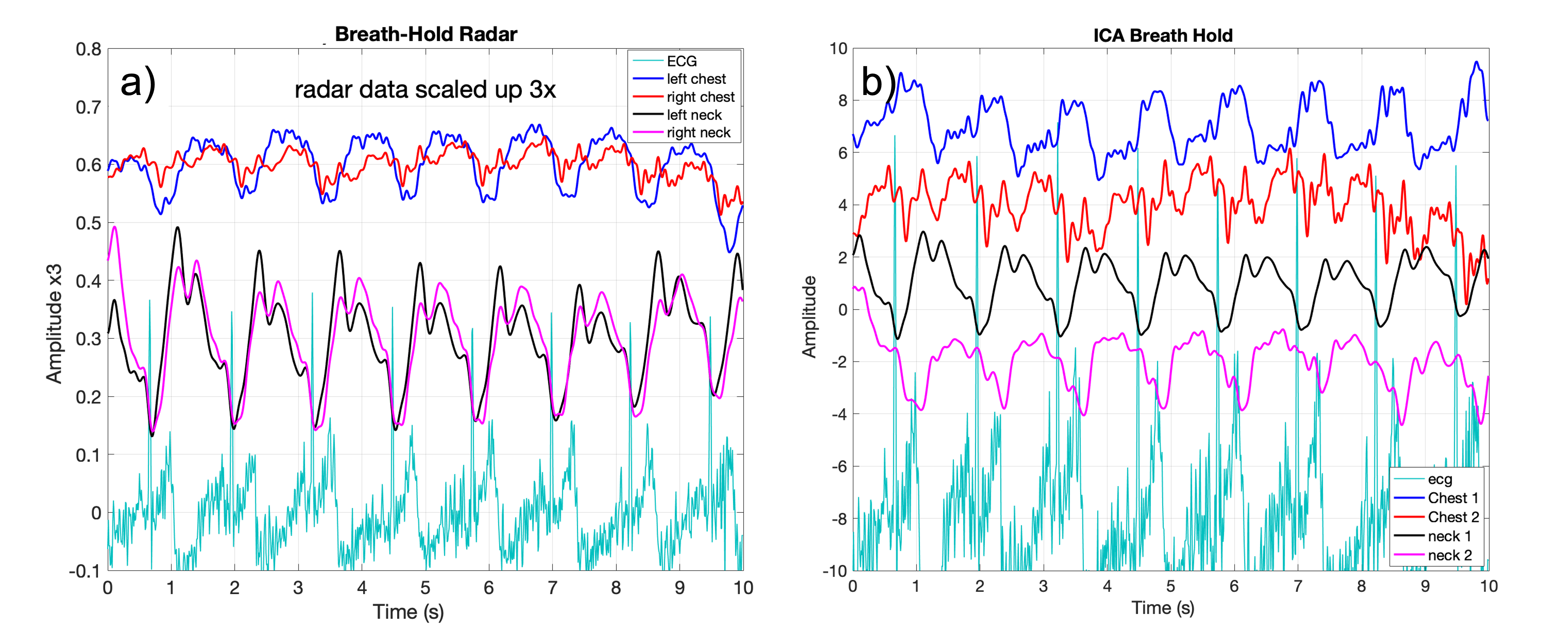
Figure 4a shows free breathing data from the chest pair (blue/red) and neck pair (purple/black) along with the ECG overlay. Surprisingly, the neck vessel pulses (carotid, JVP) yield radar signal levels similar in scale to respiration. The independent components are in Fig 4b. Now the chest signals have been nicely separated into a respiration component, and residual cardiac vibrations. The neck signals separate into a residual component (magenta) and a clean pulsatile waveform (black) with elements of carotid and jugular pulses. The ECG QRS complex consistently aligns with a notch in the neck pulse. Figure 5a shows breath-hold data, where now cardiac motion is directly visible on the chest waveform. Neck radar signals retain their similar structure. The independent components extraction is somewhat more mixed, but the QRS peak still aligns with a dip in the neck pulse signal (black).Discussion
When employing mm-wave radar, it is possible to overload the radar receiver if too close. We found that there should be about 5cm gap to the surface for best sensitivity. These results then indicate that a surprisingly high fidelity pulsatile signal from the carotid and perhaps jugular venous pulse is achievable with the neck radars. By comparison, respiration typically obscures heart motion sensing in the chest signals. However, a swallow motion will undoubtably impact the neck signals. Even so, one could easily imagine a head coil that natively embeds dual neck radars, or even a neck pillow with embedded radars for independent synchronization of brain scans with cardiac pulse. Compared to the chest signal, both carotid and jugular pulse waveforms represent direct windows into the left ventricle output and right atrium input respectively and thus bracket the ECG QRS signal.Conclusion
MM-wave radar sensing of neck vessels shows promise for high fidelity non-contact cardiac sensing. By its nature, subjects almost always lie down in the scanner, so radars can be repeatably placed near the neck. In this approach, there would be no need for MRI coils to couple to these signals as is done in pilot tone methods. This motivates future work to make these devices MRI-compatible and with associated interfacing that is robust to the MRI RF/gradient pulse environment.Acknowledgements
The authors would like to thank GE Healthcare for research support, and acknowledge funding from NIH grants R01EB019241, R01EB012031, U01EB029427, U01EB026412.References
[1] T Vahle, M Bacher, D Rigie, M Fenchel, P Speier, J Bollenbeck, KP Schafers, B Kiefer, and FE Boada. Respiratory Motion Detection and Correction for MR Using the Pilot Tone. Invest. Radiol., 55:153–159, 2020.
[2] J Ludwig, P Speier, F Seifert, T Schaeffter, and C Kolbitsch. Pilot Tone-Based Motion Correction of Prospective Respiratory Compensated Cardiac Cine MRI. Magn. Reson. Med., 85:2403–2416, 2021. doi:10.1002/mrm.28580.
[3] S Anand, M Lustig. Beat Pilot Tone: Exploiting Preamplifier Intermodulation of UHF/SHF RF for Improved Motion Sensitivity over Pilot Tone Navigators, ISMRM 2021.
[4] W Lee, J Pauly, S Vasanawala, G Scott, Radar signal integrity investigation for in-bore vital sensing applications, Proc 30th ISMRM, p724, June 2023.
[5] S Suzuki, M Hoshiga, K Kotani and T Asao. Assessment of Non-Contact Measurement Using a Microwave Sensor to Jugular Venous Pulse Monitoring, J Biomed Sci Eng, 14, pp94-102, 2021.
[6] K Renesmee, J Pauly, F Robb, S Vasanawala, and G Scott. Continuous Wave Radar for Carotid Pulse Sensing in Magnetic Resonance Imaging, Proc 30th ISMRM, p4543, June 2023.
Figures