0676
A 16-Ch Elastic Thin RF Coil Array for Whole Brain Concurrent TMS-fMRI1MR Research, Department of Psychiatry, Columbia University, New York, NY, United States, 2New York State Psychiatric Institute, New York, NY, United States, 3Columbia MR Research Center, Columbia University, New York, NY, United States
Synopsis
Keywords: RF Arrays & Systems, RF Arrays & Systems, TMS
Motivation: The low TMS efficiency and complexity of the setup for whole brain concurrent TMS-fMRI remain challenging due to the lack of feasible RF coil arrays.
Goal(s): We proposed a 16-channel elastic whole brain RF coil array to increase the TMS efficiency and flexibility.
Approach: We developed a highly flexible close-fitting coil former with 3D printing and evenly placed the 16 coil loops made of flexible shielding sleeves on the former.
Results: The measured TMS efficiency was about 80% at the inner wall of the coil array. The SNRs of experimental images were comparable with those acquired using Nova 32-ch coil array.
Impact: The proposed 16-ch elastic coil array was capable of significantly improving the TMS efficiency and simplifying the setup of whole brain concurrent TMS-fMRI.
Introdcution
The combination of transcranial magnetic stimulation (TMS) and functional magnetic resonance imaging (fMRI), concurrent TMS-fMRI has demonstrated increasing capability and importance for the treatment and understanding of psychiatric and neurological disorders 1,2. First, Concurrent TMS-fMRI enables an investigation of the immediate effects of TMS and therefore helps us understand the underling mechanism of TMS. Second, to understand the causal aspects of brain function, we need TMS to perturb ongoing regional processing of the brain during fMRI. However, the low TMS efficiency and complexity of the setup for whole brain concurrent TMS-fMRI remain challenging due to the lack of feasible RF coil arrays though several dedicated coil arrays have been investigated 3-5, including a 7-ch array for reginal brain imaging 3 and an array with multiple TMS coils 4. We presented a 16-ch whole brain RF coil array with an elastic thin wall to address the change.Material and Methods
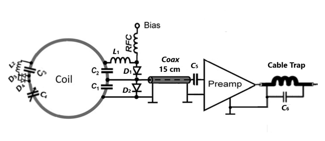
The coil former was composed of a rigid base and a flexible elliptic cylinder with an inner minor axis of 190mm and an inner major axis of 210mm. The base was 3D-printed with PLA filaments (Hatchbox3D, CA). The elliptic cylinder was 3D-printed with TPU filaments (NinjaFlex, NinjaTek, PA). The thickness of the entire wall was 10mm with a gap of 6 mm between the inner wall and outer wall for accommodating coil loop circuits. The elliptic cylinder is 90o-rotatable so the TMS coil can be positioned to target stimulation at frontal lobes, lateral lobes, and occipital lobes as needed (Figure 1). The coil loops were elliptical and had a minor axis of 100-110 mm in azimuthal direction and a minor axis of 90-100 mm in longitudinal direction (B0-direction). The loops were made of flexible tin-coated copper shielding sleeve. Adjacent loops were overlapped by a critical distance for primary decoupling. Each loop was connected to a low input impedance preamplifier for decoupling and actively detuned by bias pulses with a trap circuit formed by C2, D1, and L1 and passively detuned with C3, D3, D4 and L2 during RF transmission. A cable trap was built at the output of the preamplifier to choke surface currents (Figure 2). MR images were acquired from a spherical agar phantom having a diameter of 180mm in a 3T MRI scanner (GE Premier) using a 3D FSPGR pulse sequence (TR=30ms, TE=3.2ms, Flip Angle =20, FOV = 256x256 mm2, Matrix =256x256, Slice Thickness = 1mm, NEX=1, Bandwidth=31.25kHz) with acceleration factors (R) of 2 and 4 respectively. For comparison, the images were also acquired using a Nova 32-ch array with similar inner dimensions. To evaluate the TMS efficiency, TMS magnetic fields were measured over the distance from the outer wall to the center of the array.Results and Discussion
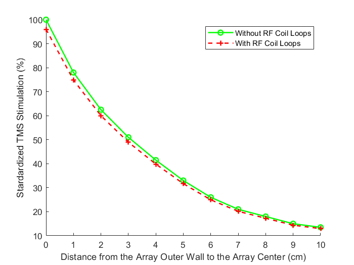
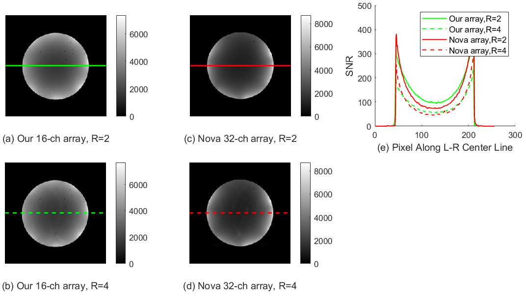
With the TMS magnetic fields standardized as 100% at the outer wall of the RF coil array, the measured TMS magnetic fields attenuated by about 22%,37%, 65%, and 85% at the distances of 1 cm, 2 cm, 5 cm, and 10 cm respectively, indicating that the TMS coil should be positioned no more than 1 cm off to achieve 80% efficiency at the subject skull (Figure 3, green line). In addition, the TMS efficiency slightly dropped when passing through the RF coil loops (Figure 3, red line). The images acquired using the proposed coil array were smooth with high quality. With R=2, the SNRs were 99 in the image center and 302 in the periphery (Figure 4, green line). With R=4, the SNR decreased by about 40% to 58 and 186 respectively (Figure 4, dashed green line). In comparison, the SNRs of the images using the Nova coil array were 75 in the center and 392 in the periphery with R=2 (Figure 4, red line) and 51 in the center and 261 in the periphery with R=4 (Figure 4, dashed green line). Thus, the overall average SNRs of the two coil arrays are comparable.Conclusions
The flexibility and thickness of the RF coil array are crucial for the whole brain concurrent TMS-fMRI. To achieve high TMS efficiency, the coil thickness should not be more than 10 mm and the coil must be highly flexible for close-fitting. Our 16-ch elastic thin coil array with shielding sleeve loops significantly improved the TMS efficiency while maintaining high MR image quality. Future work will focus on arrays with more coil elements and better stretchability for fast concurrent TMS-fMRI.Acknowledgements
No acknowledgement found.References
1. Lefaucheur J-P, et al. Evidence-based guidelines on the therapeutic use of repetitive transcranial magnetic stimulation (rTMS): an update (2014-2018). Clin Neurophysiology. 131(2020): 474-528.
2. Yuki Mizutani-Tiebel, et al. Concurrent TMS-fMRI: Technical Challenges, Developments, and Overview of Previous Studies. Frontiers in Psychiatry. 13 (2022) :1-15
3. Navarro de Lara LI, et al. A novel coil array for combined TMS/fMRI experiments at 3 T. Magn Reson Med. 74(2015):1492–501.
4. Lucia I. Navarro de Lara, et al. A novel whole-head RF coil design tailored for concurrent multichannel brain stimulation and imaging at 3T. Brain Stimulation 16 (2023): 1021-1031
5. William Mathieu, et al. Radio-Frequency Coil Array for Improved Concurrent Transcranial Magnetic Stimulation and Functional Magnetic Resonance Imaging. Annu Int Conf IEEE Eng Med Biol Soc. 2019 Jul: 6814-6817
Figures
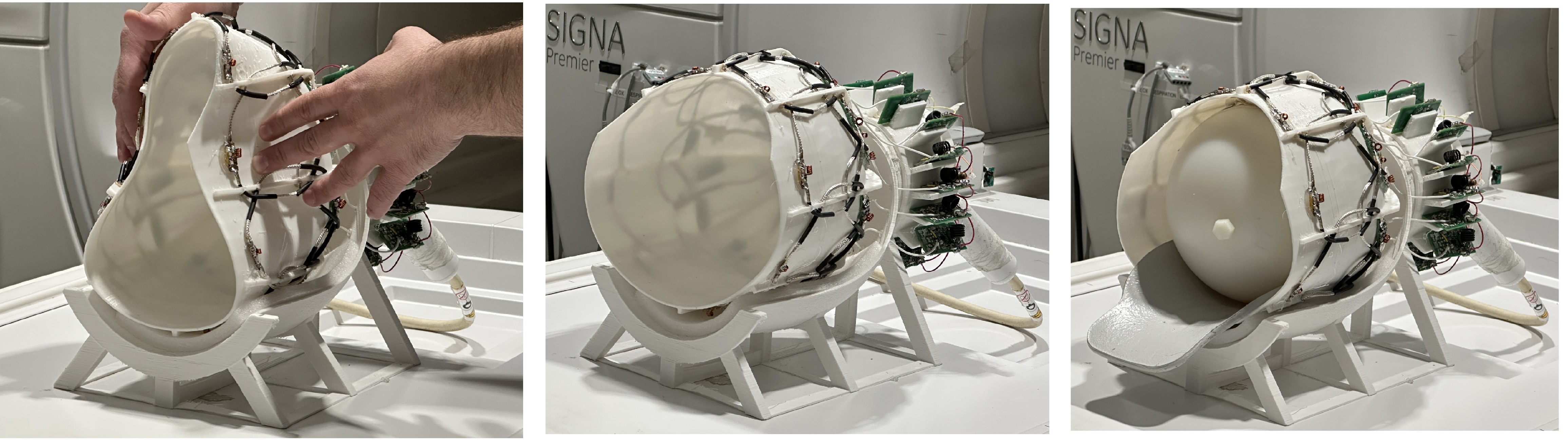
Figure 1. Photos of the implemented 16-ch coil arrays with high flexibility and resilience. Left: squeezed; Middle: unloaded; Right: Loaded.