0670
Development of a Compact Head-only Scanner with a Window and Shoulders Outside its Vertical Bore.1Center for Magnetic Resonance Research, Department of Radiology, University of Minnesota, Minneapolis, MN, United States, 2Department of Biomedical Engineering, Columbia University, New York, NY, United States, 3Robinson Research Institute, Victoria University of Wellington, Wellington, New Zealand, 4Centro de Imagens e Espectroscopia por Ressonância Magnética - CIERMag - São Carlos Physics Institute, University of São Paulo – IFSC-USP, São Carlos, Brazil, 5Department of Radiology and Biomedical Imaging, Magnetic Resonance Research Center, Yale University School of Medicine, New Haven, CT, United States, 6Air Liquide, Paris, France, 7Tranzpower Limited, Wellington, New Zealand, 8Victoria University of Wellington, Wellington, New Zealand, 9Dreiform GmbH, Hürth, Germany, 10Division of Neuroradiology, Massachusetts General Hospital, Boston, MA, United States, 11Department of Radiology, Columbia University Medical Center, New York, NY, United States, 12Department of Biomedical Engineering, University of Minnesota, Minneapolis, MN, United States
Synopsis
Keywords: Hybrid & Novel Systems Technology, Hybrid & Novel Systems Technology, New Devices, Gradients, Magnets, Head-Only
Motivation: MRI has evolved into an indispensable tool, but remains inaccessible to much of the world’s population.
Goal(s): To build a compact, low-cost, mid- to high-field MRI system capable of producing diagnostic-quality images.
Approach: A complete redesign of MR scanner architecture and key technologies; including a compact high temperature superconducting magnet, multi-coil gradient array, and digital spectrometer. The system required extensive testing prior to integration and initial imaging.
Results: Initial experiments produced high-resolution images despite using an extremely inhomogeneous magnetic field from the compact 0.7 tesla magnet.
Impact: This work represents a significant milestone within the MRI community to address the problems in accessibility and under-utilization facing MRI today. By focusing on ways to develop portable, low-cost systems, the accessibility of this imaging modality can increase substantially.
Introduction
Recent advancements in technology and magnet design are rekindling the use of MRI scanners with magnetic fields between 0.5 and 1 tesla (T). Our main objective is to make these MRI systems more affordable and portable1,2. For lower magnetic field strengths, a persistent issue is the low signal-to-noise ratio (SNR) limiting image quality and hampering the wide spread adoption of these systems1,3-7. Moving to mid-field strengths (0.5 T to 1 T) allows for significant SNR improvement and facilitates direct comparison with high-field clinical images (1.5 T to 3 T) while reducing cost1,8-10. Here, we present the progress made towards developing, manufacturing, and testing a compact 0.7 T scanner that requires minimal infrastructure compared to traditional clinical systems.Methods
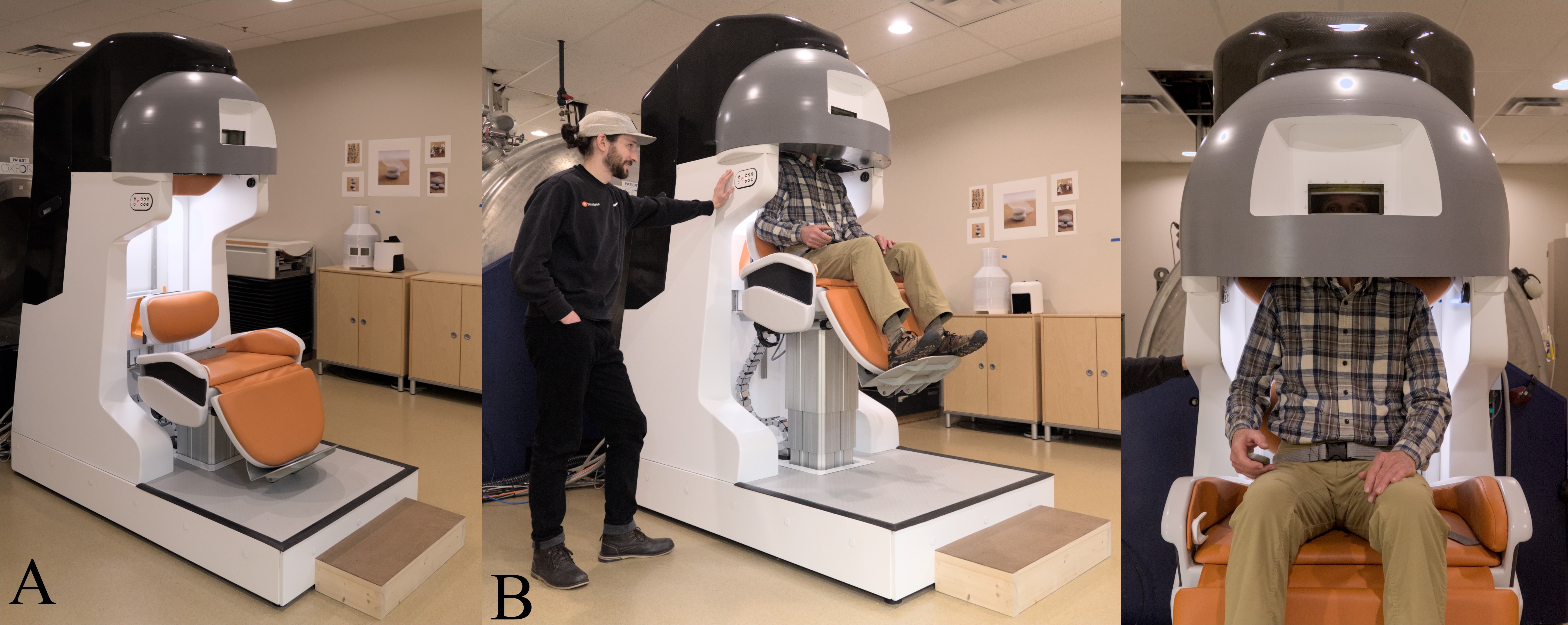
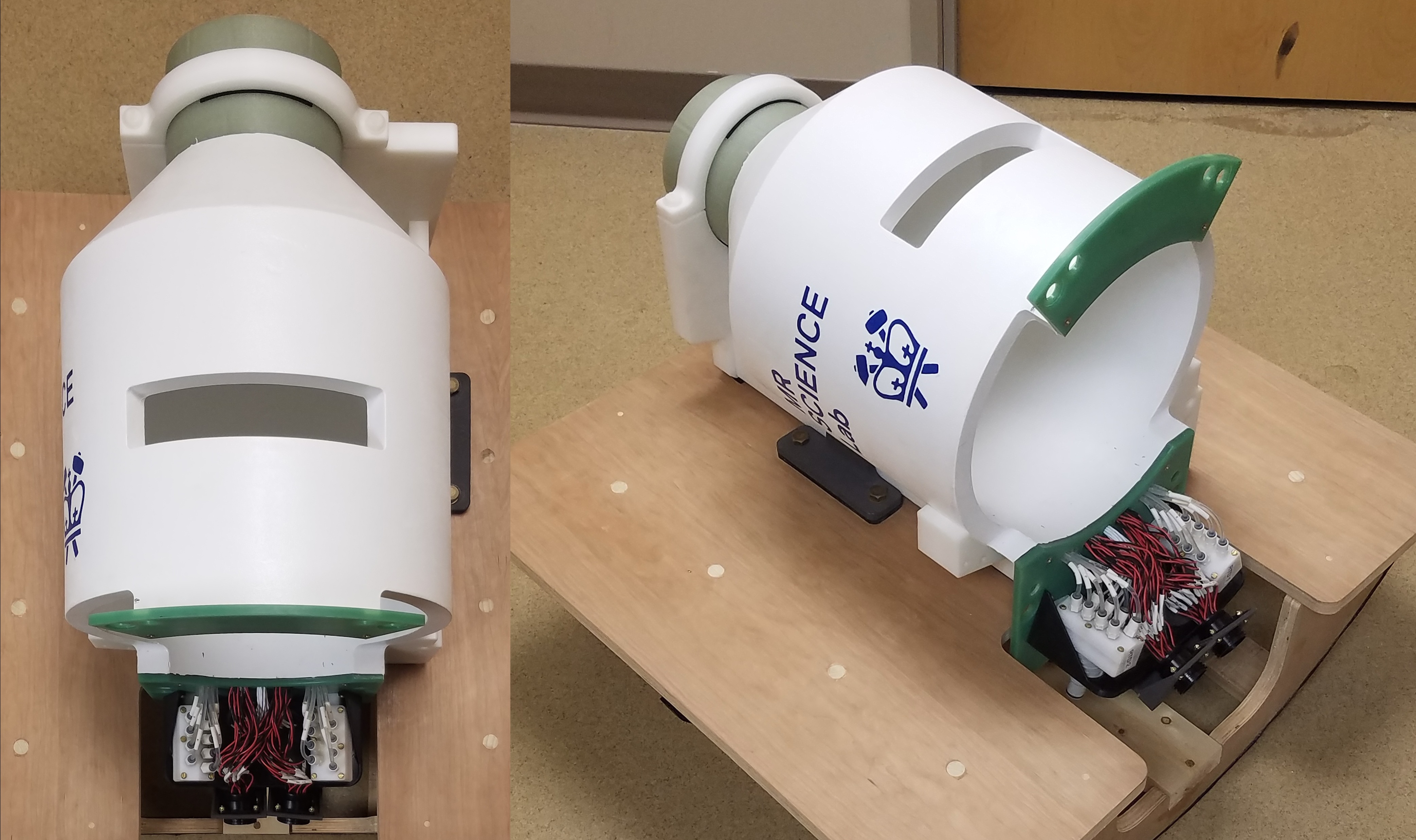
The scanner utilized several novel pieces of technology to not only improve its portability but also to minimize the infrastructure necessary to collect high quality MRI images. The heart of the system is a new, high-temperature superconductor (HTS) magnet that is highly compact, weighing only 400 kg. The housing is designed to completely exclude the shoulders during imaging with an aperture allowing the patient to see out (Figure 1). The magnet was designed to have 20 kHz peak-to-peak variation in magnetic field over a 200 x 200 x 150 mm ellipsoidal imaging volume after passive shimming.To maximize the flexibility of the encoding fields, the scanner was constructed to utilize a multi-coil array consisting of 31 direct-current coils independently driven allowing for simultaneous dynamic shimming and pulsed gradient B0 fields11,12. The effective gradient fields necessary for imaging are generated by the linear combination of the 31 coils played out in time (Figure 2). The gradient strengths for each imaging sequence are calculated using the PyMR (Python Magnetic Resonance)13-15 development environment and then played out using a multi-channel digital magnetic resonance spectrometer (DMRS)15 and a 32-channel gradient controller16.
With the reduction in the static field uniformity of this magnet, imaging sequences must be tailored to be resilient to large offsets and to minimize distortions without compromising the image fidelity. As the frequency variation across the imaging volume is fairly substantial, high-bandwidth RF pulses must be employed to adequately excite a sufficient volume. In addition, sequences must be modified such that they employ a large readout bandwidth along the frequency-encoding dimension to minimize misregistration. Given these requirements, three 3D sequences have been implemented on the system: a short echo-time (TE) GRE, LACE17, and MP-SSFP18,19. All of these sequences have shown resilience to large inhomogeneities and utilize large bandwidth pulses.
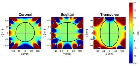
Leading up to the final assembly of the HTS magnet, all of the subsystems were tested together to ensure their compatibility and to address any issues before placement in the HTS magnet. With the system completed and the HTS magnet delivered to the CMRR, the final uniformity of the static field was measured. The static field mapping was performed with a 3-axis translation stage moving a Hall probe throughout imaging volume.
Results
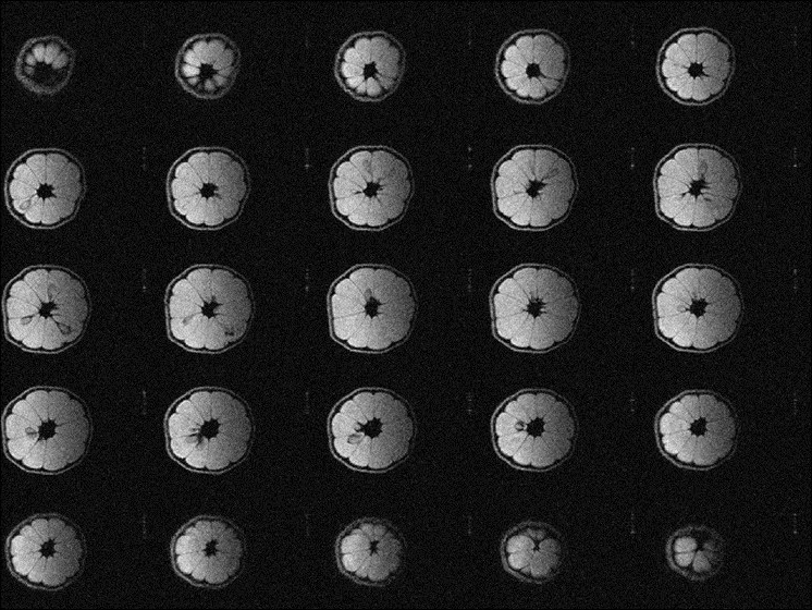
The measured variation in field centered at the region-of-interest (ROI) was 34 ppm (1 kHz) over a 10-cm diameter spherical volume (DSV) increasing to 520 ppm (16 kHz) over a 20-cm DSV (Figure 3). To evaluate the performance of the imaging system, a short TE 3D GRE sequence utilizing an 11-cm surface coil for RF transmission and reception was placed at the center of the ellipsoidal imaging volume. The resulting image was acquired at a resolution of 0.7 x 0.7 x 2 mm with 4 averages (scan time of roughly 9 min) and reconstructed using no spatial or sensitivity corrections (Figure 4).Discussion
During the final assembly it was discovered that the HTS magnet would not reach the designed 1.5 T field strength. When at 1.5 T, the magnet was designed to operate at 160 A at 30 K. However, during magnet commissioning, it was found the magnet was operationally limited to 81.5 A to ensure stability. The magnet is readily up-gradable to 1.5 T; however, for programmatic reasons we continued operating the magnet at 0.7 T. The final field uniformity was improved over the initial design and could be further improved by incorporating active shimming into the design of the gradient fields. Even without employing shims or eddy current compensation a high-resolution image of a lemon was easily acquired within the ellipsoidal imaging volume.Conclusion
The work presented here illustrates the successful design and implementation of a novel, compact head-only MRI system that can operate at mid- to high- magnetic fields without sacrificing significantly on image quality.Acknowledgements
This research was supported by the Biomedical Imaging & Bioengineering of the National Institutes of Health under award numbers (U01EB025153, R01EB030560, and P41EB027061), KiwiNet (NZ), and the Malcolm B. Hanson Endowed Chair.
References
- Sarracanie M, Salameh N. Low-Field MRI: How Low Can We Go? A Fresh View on an Old Debate. Frontiers in Physics. 2020 2020;8:172. doi:10.3389/fphy.2020.00172
- Marques JP, Simonis FFJ, Webb AG. Low-field MRI: An MR physics perspective. Journal of magnetic resonance imaging : JMRI. 2019/06//undefined 2019;49(6):1528-1542. doi:10.1002/jmri.26637
- Jiang M, Bian J, Li Q, et al. Zero- to ultralow-field nuclear magnetic resonance and its applications. Fundamental Research. 2021/01/01/ 2021;1(1):68-84. doi:10.1016/j.fmre.2020.12.007
- Hovis G, Langdorf M, Dang E, Chow D. MRI at the Bedside: A Case Report Comparing Fixed and Portable Magnetic Resonance Imaging for Suspected Stroke. Cureus. 2021/08/05/ 2021;13(8):e16904-e16904. doi:10.7759/cureus.16904
- Mazurek MH, Cahn BA, Yuen MM, et al. Portable, bedside, low-field magnetic resonance imaging for evaluation of intracerebral hemorrhage. Nature Communications. 2021/08/25/ 2021;12(1):5119. doi:10.1038/s41467-021-25441-6
- Cooley CZ, Stockmann JP, Armstrong BD, et al. Two-dimensional imaging in a lightweight portable MRI scanner without gradient coils. Magnetic Resonance in Medicine. 2015/02/01/ 2015;73(2):872-883. doi:10.1002/mrm.25147
- Cooley CZ, McDaniel PC, Stockmann JP, et al. A portable scanner for magnetic resonance imaging of the brain. Nature Biomedical Engineering. 2021/03/01/ 2021;5(3):229-239. doi:10.1038/s41551-020-00641-5
- Wald LL, McDaniel PC, Witzel T, Stockmann JP, Cooley CZ. Low-cost and portable MRI. Journal of Magnetic Resonance Imaging. 2020/09/01/ 2020;52(3):686-696. doi:10.1002/jmri.26942
- Sarracanie M, LaPierre CD, Salameh N, Waddington DEJ, Witzel T, Rosen MS. Low-Cost High-Performance MRI. Scientific Reports. 2015/10/15/ 2015;5(1):15177. doi:10.1038/srep15177
- Geethanath S, Vaughan JT, Jr. Accessible magnetic resonance imaging: A review. Journal of magnetic resonance imaging : JMRI. 2019/06//undefined 2019;49(7):e65-e77. doi:10.1002/jmri.26638
- Juchem C, Theilenberg S, Kumaragamage C, et al. Dynamic multicoil technique (DYNAMITE) MRI on human brain. Magnet Reson Med2020. p. 2953-2963.
- Theilenberg S, Shang Y, Ghazouani J, et al. Design and realization of a multi-coil array for B(0) field control in a compact 1.5T head-only MRI scanner. Magn Reson Med. Sep 2023;90(3):1228-1241. doi:10.1002/mrm.29692
- Pizetta DC. PyMR: A Framework for Programming Magnetic Resonance Systems. PhD thesis. Instituto de Física de São Carlos; 2018. DOI: 10.11606/T.76.2019.tde-06052019-103714
- Pizetta DC, Shimada DHT, Falvo M, et al., inventors. PyMR—a framework for programming magnetic resonance systems. Brazil Software Registry No. BR512019001829-0. 2017.
- Martins MJ, Vidoto ELG, Tannús A. inventors; Universidade de São Paulo, assignee. Espectrômetro para uso em sistemas de ressonância magnética e sistemas de ressonância magnética. Brazil Software Registry No. BR102015000624-1. 2015
- Nixon TW, McIntyre S, de Graaf RA. The design and implementation of a 64 channel arbitrary gradient waveform controller. 2017:969.
- Theilenberg S, Kumaragamage C, McIntyre S, Nixon TW, Juchem C, de Graaf RA. Low-Angle Combined-Echo (LACE) Imaging in Highly Inhomogeneous B Magnetic Fields. 2021
- Kobayashi N, Parkinson B, Idiyatullin D, et al. Development and validation of 3D MP-SSFP to enable MRI in inhomogeneous magnetic fields. Magnet Reson Med. 2021;85:831-844. doi:10.1002/mrm.28469
- Mullen M, Garwood M. Contemporary approaches to high-field magnetic resonance imaging with large field inhomogeneity. Prog Nucl Mag Res Sp. 2020;120-121:95-108. doi:10.1016/j.pnmrs.2020.07.003
Figures