0476
Development of the H12 insertable head gradient set designed for 10.5T and optimized for both peripheral nerve stimulation and magnet heating1Radiology, Stanford University, Stanford, CA, United States, 2Roemer Consulting, Lutz, FL, United States, 3Robarts Research Institute, University of Western Ontario, London, ON, Canada, 4Stanford University, Stanford, CA, United States, 5CMRR, University of Minnesota, Minneapolis, MN, United States
Synopsis
Keywords: Gradients, Gradients, Peripheral nerve stimulation, magnet heating
Motivation: Two interactions between gradient coils and their environment severely limit imaging performance: stimulation of peripheral nerves in human subjects and deposition of heat energy into the superconducting main magnet leading to helium loss or quench. This heating increases significantly for higher B0 and gradient switching frequencies.
Goal(s): To address the above limitations by recasting the gradient design problem in a unique way to simultaneously minimize both of these interactions.
Approach: Using these new methods, we designed and modeled a head gradient coil: H12.
Results: We achieved >1.4 fold PNS improvement and >6 fold lower magnet heating compared to existing state-of-the-art head gradient coils.
Impact: Our method allows the design and real-world use of stronger and faster-switching gradients than any in existence, while minimizing peripheral nerve stimulation and excessive magnet heating. The potential impact is especially high for head gradients operating at ultra high field.
Introduction
As a result of the push for ever-higher gradient performance, there are two problematic interactions that now limit operational performance: peripheral nerves stimulation (which can be painful), and excessive power deposition into the superconducting main magnet). These problems are a particular concern for head gradients operating at high switching frequencies and ultra high B0. The gradient system operating limits can be adjusted to avoid these problematic interactions, at the expense of imaging performance. Our goal was to address these problems more fundamentally, by recasting the gradient design problem to minimize these interactions and to allow for the creation of optimal gradient designs that constrain both peripheral nerve stimulation and magnet heating.Methods
Our minimum-electric-field gradient design method1 minimizes the peak electric field magnitude (Emax) on the surface of simplified body models positioned in the gradient coil. Emax per unit slew rate is an accepted predictor of PNS thresholds according to regulatory standards2 and our own work3. Our method can be used to optimize gradient designs over a large and diverse set of body models, thereby achieving global population-wide PNS optimization.Our magnet-heating-minimized gradient design concept is summarized as follows. We represent the gradient fringe field by a current density pattern on an equivalent surface, which can be decomposed into a set of basis functions. Each basis function is then propagated through a multiphysics gradient-cryostat-interaction (GCI) model that couples the mechanical vibrations with the induced currents that result in frequency-dependent power deposition into the cryostat. These basis functions and associated power deposition matrices are then incorporated into our gradient design code.
Figure 1 illustrates these new design concepts, which serve to optimize the gradient coil design to meet desired gradient performance constraints while simultaneously minimizing stored magnetic energy in the gradient coil (slew rate), peak electric field impinging on the body (PNS), and power deposited into the magnet (GCI).
We employed the above novel concepts to design the H12 head gradient. We set the following design targets: inner diameter 400mm, outer diameter 616mm, length 1050mm, shoulder corner to isocenter distance 170mm, imaging region diameter 240mm, target gain (sensitivity) ≥220 µT/m/A, target inductance ≤440 µH, target Emax ≤7mV/m per T/m/s, target 10.5T magnet heating ≤6W for 40mT/m gradient amplitude, target gradient cooling ≥40kW. These targets would produce gradient performance parameters of Gmax 264mT/m at 1200A, Smax 1000T/m/s at 2000V, with PNS thresholds ≥1.4 fold higher and magnet heating ≥5 fold lower than existing head gradients.
Results
Figure 2 shows the optimized H12 X, Y and Z wire patterns, with primary windings in red and shield windings in yellow.Figure 3A shows H12 X, Y and Z wire patterns superimposed on a body model which displays surface electric fields. Emax values for X, Y, and Z gradient axes are 6.5, 6.0, 7.0 mV/m, respectively. Figure 3B shows PNS thresholds plotted in ∆Gstim vs ∆t space4, indicating the higher predicted PNS thresholds for H12 compared to three other head gradients and one body gradient3,5. Solid lines indicate measured thresholds whereas dotted lines represent Emax-predicted thresholds, showing the close match to measured thresholds whenever both were available.
Figure 4 shows the calculated power deposition into the magnet for 40mT/m sinusoidal gradient amplitude, spanning frequencies from 500 to 3000 Hz, for a head gradient with design parameters equivalent to H12 but without magnet-heating minimization (solid curves), compared to the magnet-heating-minimized H12 design (dashed curves). Large reductions of power deposition are shown: ~10-fold for X and Y and ~6-fold for Z.
Figure 5A shows the construction concept in CAD design view, with a foundation layer representing the inner shell (cylindrical main section plus conical shoulder section) plus bent rungs that locate the X-primary wires. Y and Z primary layers are added via the placement of similar bent rungs on top of the previously wound layer. Shield windings are laid into straight rungs. All support parts are 3D printed, and all conductors are doubly-insulated 6.5mm OD hollow copper conductor. Figure 5B shows the early construction phase of H12, in which the inner shell including X-primary rungs has been printed and X-primary wires have been wound.
Discussion and Conclusion
We have designed, modeled, and begun to build the H12 head gradient coil, which is intended for use in the 10.5T magnet at CMRR. Gradient performance is among the highest of any demonstrated to date, with significant improvements in strength, slew rate, cooling, PNS and GCI performance over other gradients; these are the result of our ability to globally optimize gradient design subject to Emax and magnet-heating constraints.Acknowledgements
The authors gratefully acknowledge research support from NIH U01 EB025144 and NIH R01 EB025131. We also acknowledge support from the Sim4Science program at ZurichMedTech.References
1. Roemer, P.B. & Rutt, B.K. Minimum electric-field gradient coil design: Theoretical limits and practical guidelines. Magn Reson Med 86, 569-580 (2021).
2. IEC. Medical electrical equipment – Part 2-33: Particular requirements for the basic safety and essential performance of magnetic resonance equipment for medical diagnosi. International Electrotechnical Commissioin 60601-2-33 Edition 3.2(2015).
3. Roemer, P.B., Wade, T., Alejski, A., McKenzie, C.A. & Rutt, B.K. Electric field calculation and peripheral nerve stimulation prediction for head and body gradient coils. Magn Reson Med 86, 2301-2315 (2021).
4. Chronik, B.A. & Rutt, B.K. Simple linear formulation for magnetostimulation specific to MRI gradient coils. Magn Reson Med 45, 916-919 (2001).
5. Davids, M., et al. Peripheral nerve stimulation informed design of a high-performance asymmetric head gradient coil. Magn Reson Med 90, 784-801 (2023).
Figures
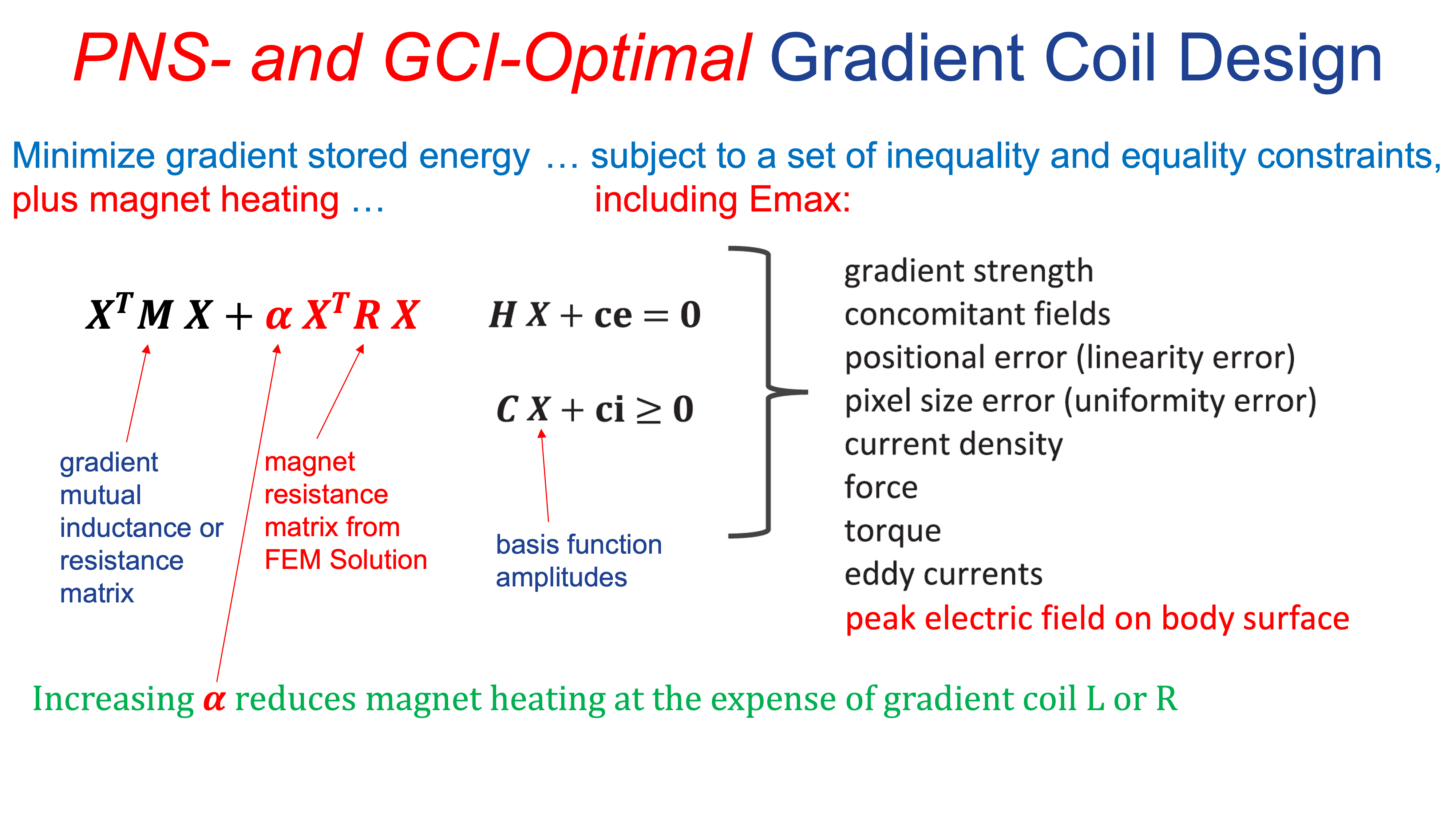
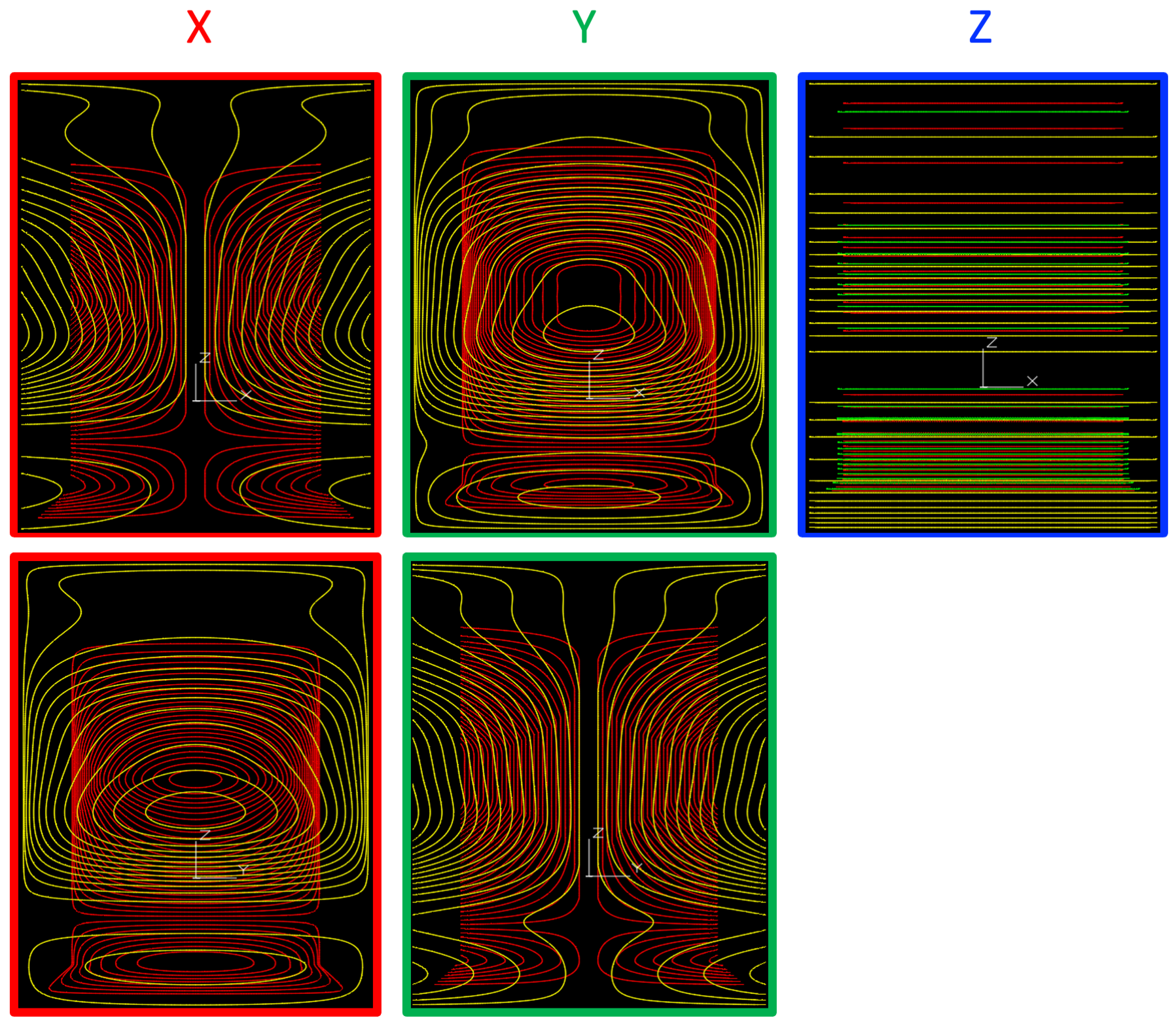

Figure 3. A. H12 gradient design, showing wire patterns for X, Y and Z gradients. Electric field is mapped onto the surface of a 50th percentile male body model, and the spatial peak value Emax is shown. B. Emax-predicted PNS thresholds for H12 (blue dotted) compared to measured thresholds for the Siemens Impulse gradient (teal solid), and the measured and Emax-predicted thresholds for two other head gradients built by our group, LH7 (red) and H3 (purple) as well as a generic body gradient (cyan).
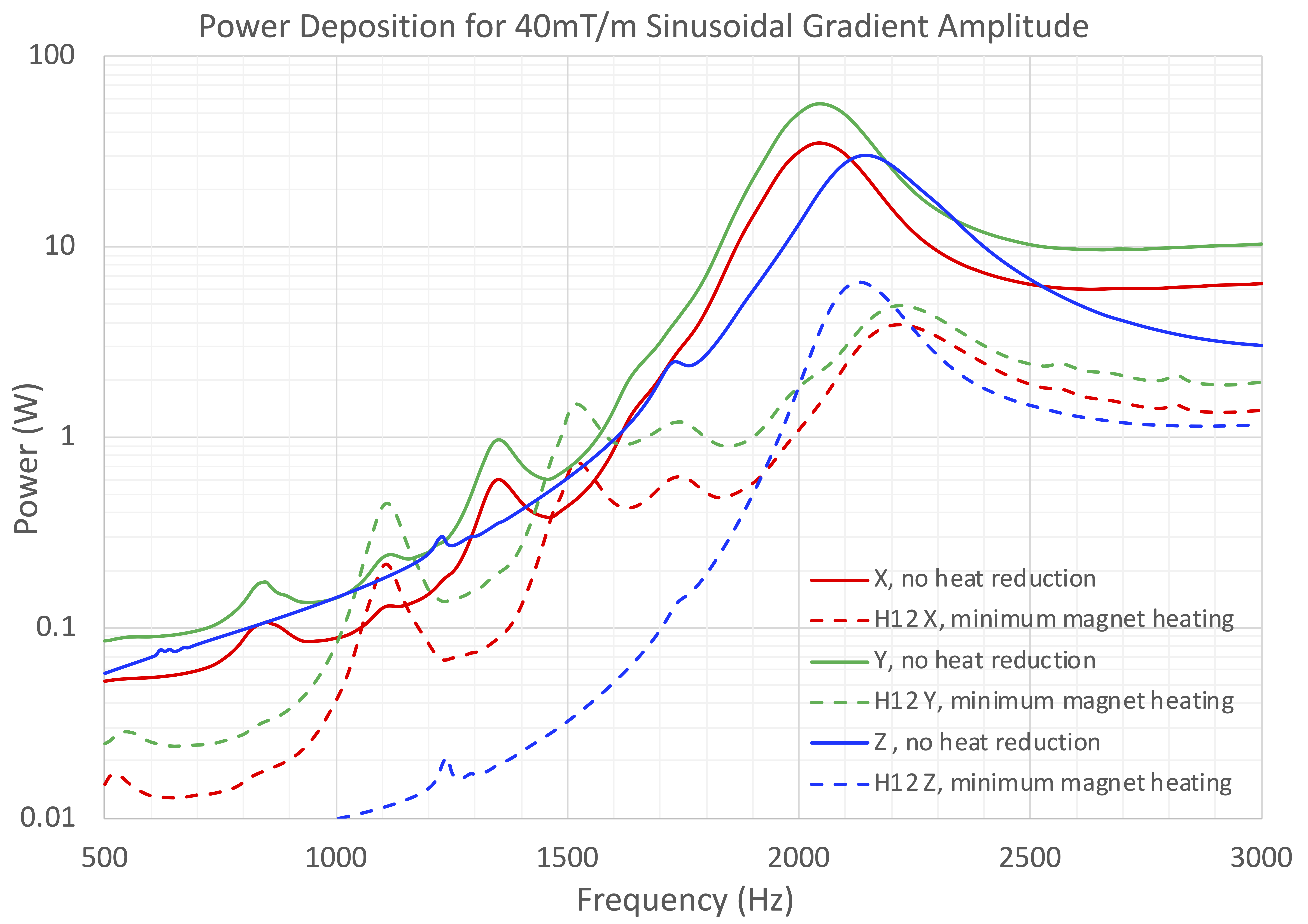
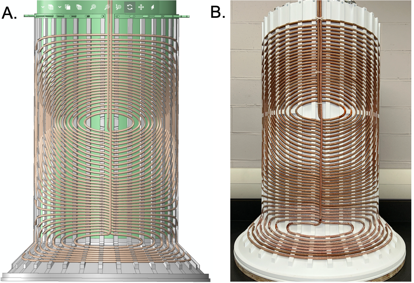
Figure 5. A. CAD design: Construction of H12 starts with a wholly 3D-printed inner shell with integrated rungs that locate the X primary windings, as shown. Remaining layers are built radially outward by laying new rungs directly onto the previous layer, and winding each conductor layer into those new rungs. Conductors consist of 6.5mm OD hollow copper for all axes. B. As-built X-primary layer: Photo shows 3D-printed inner shell with first half of X-primary layer wound.