0473
Impact of RF imperfections on MRF-based and reference B1+ mapping methods with a commercial 1Tx/32Rx head coil1Physikalisch-Technische Bundesanstalt, Braunschweig and Berlin, Germany, 2Medical Physics in Radiology, German Cancer Research Center (DKFZ), Heidelberg, Germany, 3Center for Magnetic Resonance Research, University of Minnesota, Minneapolis, MN, United States, 4Einstein Center Digital Future, Berlin, Germany, 5Department of Biomedical Engineering, Technical University of Berlin, Berlin, Germany
Synopsis
Keywords: System Imperfections, System Imperfections: Measurement & Correction
Motivation: Magnetic Resonance Fingerprinting (MRF) and preparation-based reference B1+ mapping approaches yielded an unexpected B1+ offset.
Goal(s): Identify the origin of the B1+ offset.
Approach: Pick-up coil measurements to evaluate the actual RF pulse shape using a commercial 1Tx/32Rx head-coil at 7T.
Results: For the preparation-based B1+ mapping method with rectangular pulses, longer RF rise times (~100 µs) and phase variations (~10°) were observed. Furthermore, during the 21s-long MRF acquisition using sinc-pulses, an increased RF amplitude (~2.5%) was observed. By incorporating the measured RF alterations, the B1+ offset could be substantially reduced.
Impact: Unidentified effects of the RF transmission such as deviation in envelope and temporal instability affect measurements. Characterizing the RF transmission enables quantification and correction of these deviations.
Introduction
Accuracy and precision of MRI experiments strongly rely on hardware fidelity. While gradient imperfections receive considerable attention1, RF imperfections are often disregarded. RF correction methods have been proposed for complex pTx2,3 or multiband4 applications, however, imperfections within the RF-chain (amplifier and coil) would also affect absolute quantification techniques with simpler RF-waveforms, in particular precise B1+-mapping methods that are necessary for coil validation or for quantitative corrections.Here, we report deviations from the expected RF signal that we observed by pick-up coil measurements in MRF based B1+-mapping scans5 in comparison to a reference B1+-mapping approach6 using a commercial 1Tx/32Rx head-coil. Furthermore, we investigate the temporal stability of the MRF-pattern and its impact on the resulting values.
Methods
The pick-up loop experiments are performed during scanning at 7T(Magnetom7T,Siemens) with a phantom (Eurospin-TO5 tubes), using a commercial 1Tx/32Rx head-coil (Nova Medical,USA), that can receive in two modes: V32) uses the Tx birdcage also for Rx, A32) uses a separate 32-channel receive array.A previously presented, accurate MRF-based B1+-mapping technique5 using a sinusoidal flip angle (FA) pattern7(c.f. Fig.4a) was acquired together with a very slow but also accurate B1+ reference method that uses a rectangular(rect) RF preparation pulse of variable voltage6. Parameters are listed in Fig.1.
The pick-up loop signal was captured with an oscilloscope(Tektronix-DPO7254). Due to memory constraints only every 10th sinc-pulse of the MRF-pattern was recorded, allowing sparse sampling of the entire 21s-long MRF-train. Postprocessing involved demodulation, applying a 250kHz-bandwidth bandpass-filter, and down-sampling8
Results & Discussion
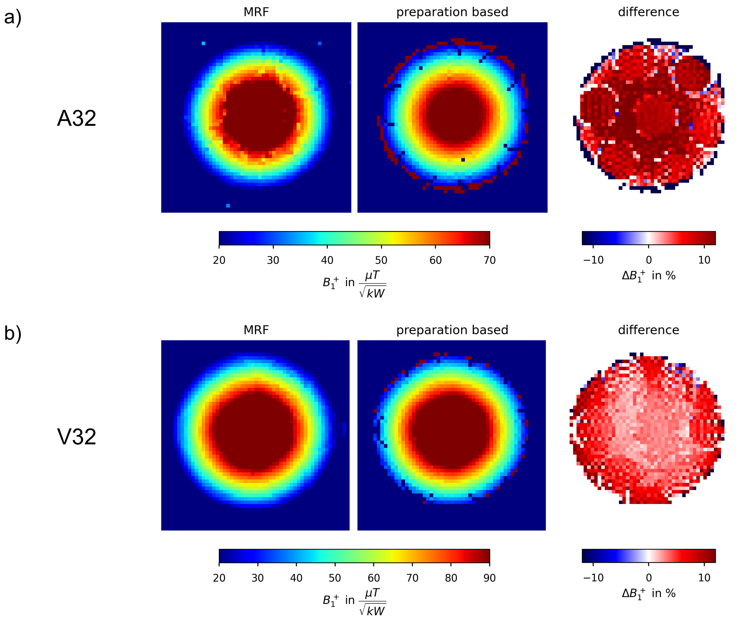
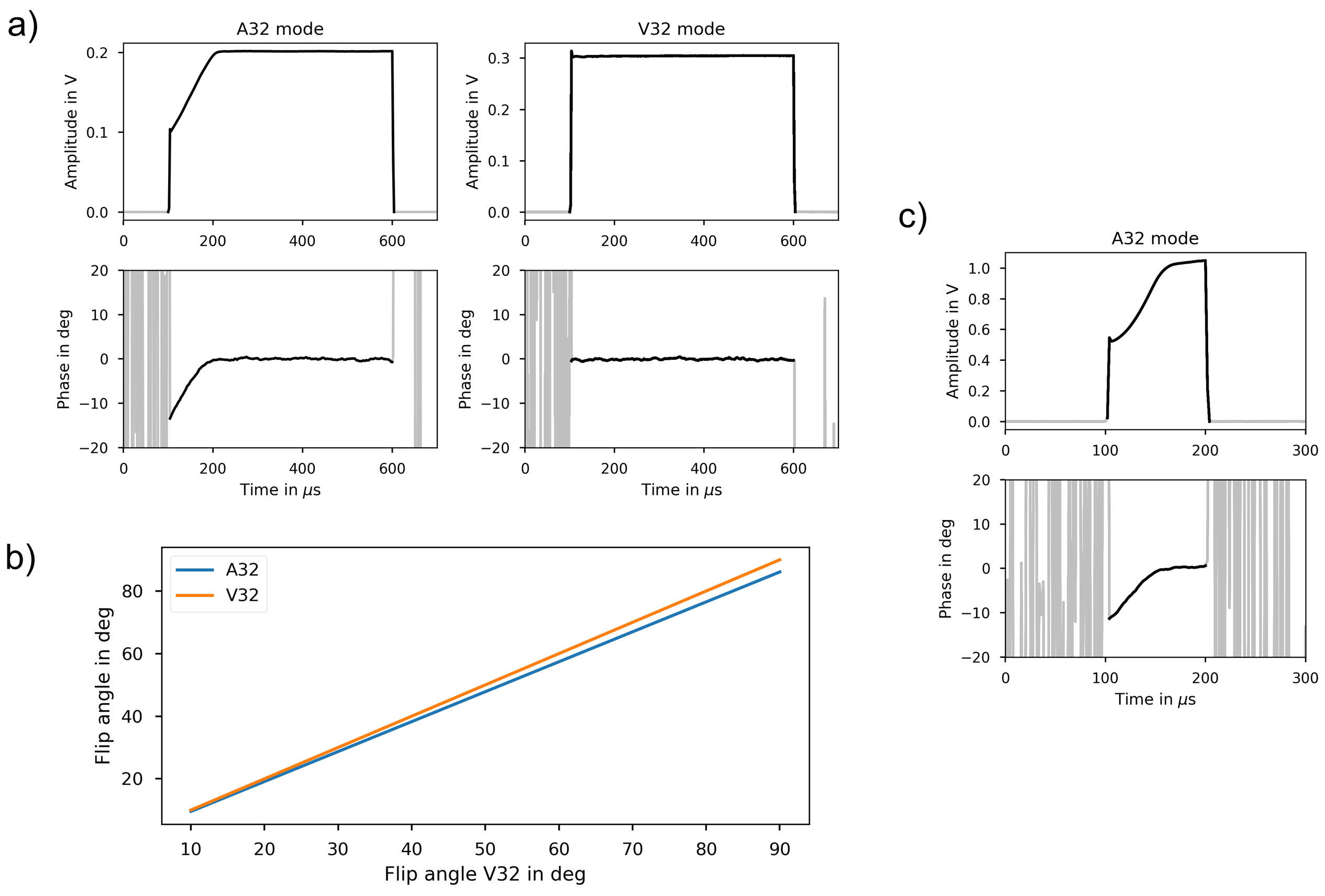
Fig.2a,b presents B1+-maps of the MRF-approach and the reference for both modes. For A32, a mean offset of 8.8% is observed across all phantom tubes, while for V32, the offset is 4.6%. Consequently, a -4.2% difference exists between the offsets of A32/V32.Focussing on this difference, Fig.3a depicts an 500µs rect-pulse for A32/V32 reflecting a strong initial 100µs deviation for A32 and, importantly, a non-constant phase, that both are absent in V32. In Fig.3b, Bloch-simulations reveal a relative FA offset of -4.3% between A32/V32, which matches the “missing” -4.3% area of the rect-pulse shape and the -4.2% difference shown in Fig.2. This effect is even more pronounced for a shorter rect-pulse duration of 100µs(Fig.3c) yielding a measured -19.1% deviation of the RF-envelope area.
In the case of V32, where the same element serves as both Tx and Rx, the transmitter remains tuned, and therefore no observable effect is present. The effect was reproduced at different sites with a similar and an upgraded MR system (TerraFit,Siemens), but neither a novel system (Terra,Siemens) nor scanning in pTx mode using the 8Tx/32Rx version of the coil showed this effect. We speculate that the effect is linked to pin-diode switching of the Tx birdcage coil.
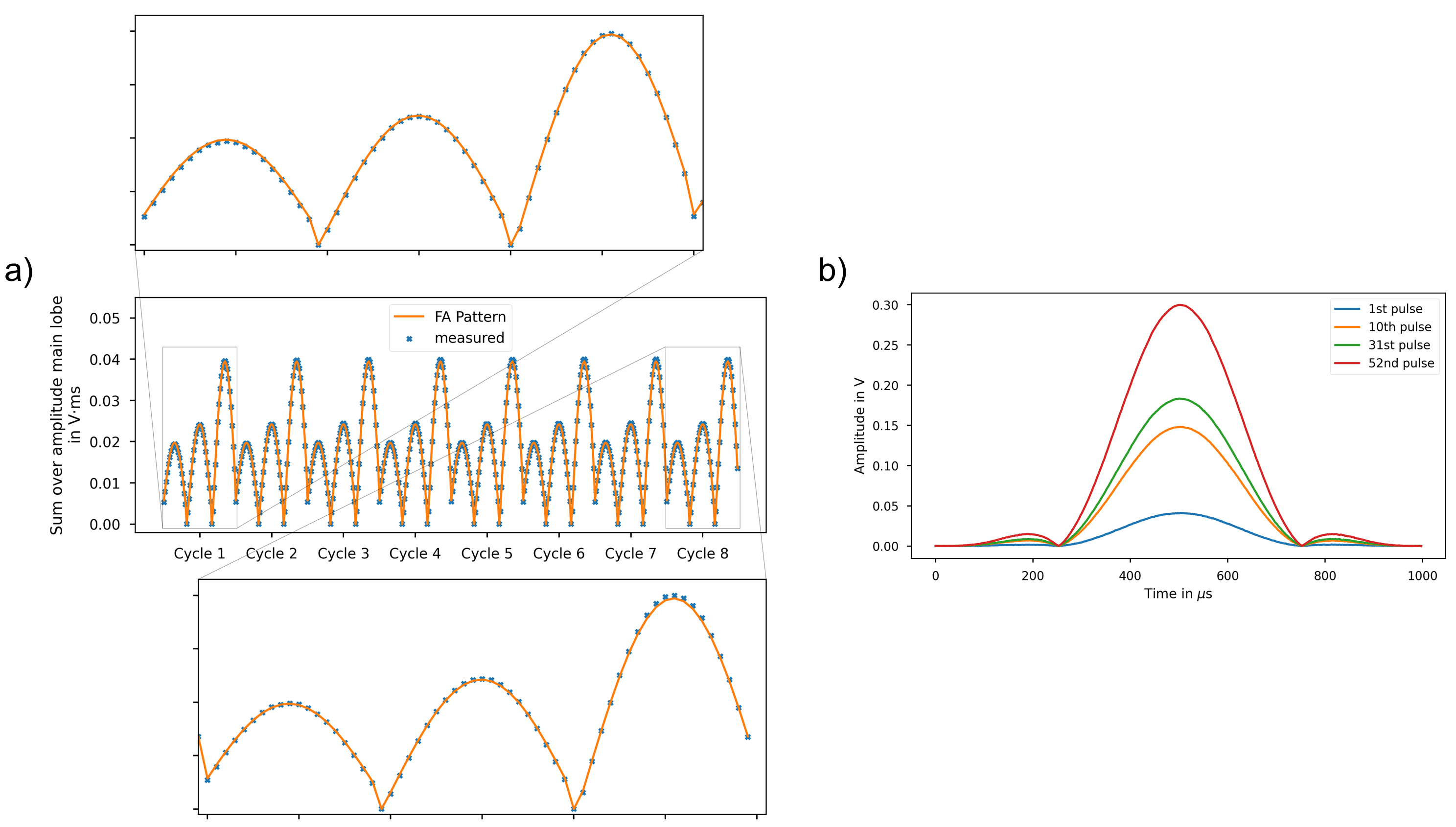
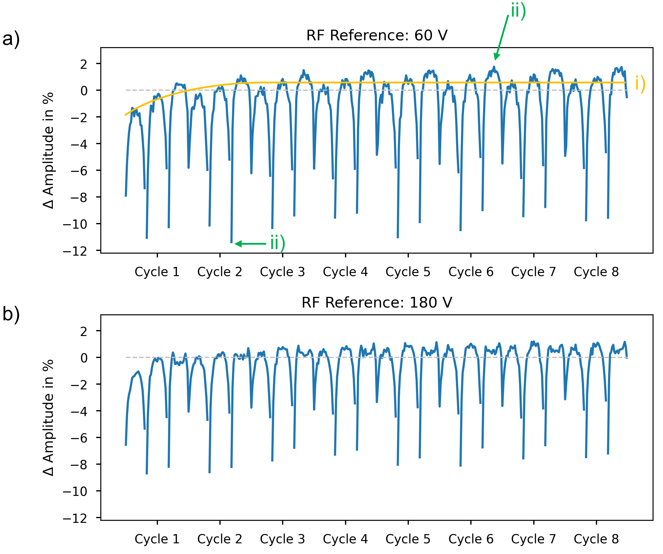
Next, the residual 4.6% difference between MRF and reference in V32(c.f. Fig.2b) was investigated. Fig.4b displays the sinc-shaped MRF-pulses for the 21s-long FA-train. Fig.4a evaluates the temporal stability of the MRF-pattern, where temporal summation of the main lobe of the single pulses is assumed to be proportional to the FA and compared to the nominal values from the FA-pattern. Measured data from the first cycle was used to scale the nominal pattern. The difference of Fig.4a is displayed in Fig.5a for closer evaluation. We observe (i) an increase in measured amplitude of ~2.5%, from the first to the last cycle and (ii) differences within one cycle become visible, with negative differences of up to -11.4% for small FAs while positive differences of up to 1.8% are seen for high FA regions. Similar results are observed for higher uRef(Fig.5b), with min/max differences of -8.6%/1.2%, respectively.
Effect (i) leads to a linear offset in the MRF B1+-maps, as less nominal RF-power is required to achieve a certain FA and the first cycle is not used in reconstruction, whereas (ii) yields a non-linear distortion of the fingerprints. First approaches to correct the FA-pattern by (ii) resulted in decreased dot-products (inferior matches) between measurements and MRF dictionary. This suggests factors biasing the pick-up loop experiments such as lower oscilloscope sensitivity at lower voltages and/or filtering.
However, the residual offset in between the MRF-based and preparation-based approach was decreased to 2.1% by incorporating the increasing amplitude (i). Remaining offsets could originate from different acquisition strategies or effects that are out of scope here such as magnetization transfer.
Conclusion
While gradient imperfections are known to be a considerable source of errors in (quantitative) MRI such as MRF that requires measuring the gradient waveform, this work suggests that considering RF waveform fidelity by using pick-up coils may be necessary to capture unidentified effects during RF transmission.Acknowledgements
We gratefully acknowledge funding from the German Research Foundation (GRK2260, BIOQIC and SCHM 2677/4-1).References
1. Vannesjo SJ, Haeberlin M, Kasper L, et al. Gradient system characterization by impulse response measurements with a dynamic field camera. Magn Reson Med. 2013;69(2):583-593.
2. Çavuşoğlu M, Dietrich BE, Brunner DO, Weiger M, Pruessmann KP. Correction of parallel transmission using concurrent RF and gradient field monitoring. Magn Reson Mater Phys Biol Med. 2017;30(5):473-488.
3. Stang PP, Kerr A, Grissom W, Pauly JM, Scott GC. Vector Iterative Pre-Distortion: An Auto-calibration Method for Transmit Arrays. In: Proceedings of the 17th Annual Meeting of ISMRM. 2009:395.
4. Landes VL, Nayak KS. Iterative correction of RF envelope distortion with GRATER‐measured waveforms. Magn Reson Med. 2020;83(1):188-194.
5. Lutz M, Aigner CS, Dietrich S, et al. Low power free-breathing absolute B1+ mapping in the human body at 7T using magnetic resonance fingerprinting. In: Proceedings of the 30th Annual Meeting of ISMRM. 2022:0386
6. Seifert F, Wübbeler G, Junge S, Ittermann B, Rinneberg H. Patient safety concept for multichannel transmit coils. J Magn Reson Imaging. 2007;26(5):1315-1321.
7. Jiang Y, Ma D, Seiberlich N, Gulani V, Griswold MA. MR fingerprinting using fast imaging with steady state precession (FISP) with spiral readout. Magn Reson Med. 2015;74(6):1621-1631.
8. Schote D. Spectrum-Pulseq MRI Console. Published online October 30, 2023. Accessed November 8, 2023. https://github.com/schote/spectrum-console
Figures