0469
Towards dense parallel-transmit coil head array: 20-channel dipole and self-decoupled overlapped loop coil array design1School of Biomedical Engineering & Imaging Sciences, King's College London, London, United Kingdom
Synopsis
Keywords: RF Arrays & Systems, RF Arrays & Systems
Motivation: Traditional dense transmit arrays for 7T imaging face decoupling challenges. A novel approach using self-decoupled coils can potentially overcome these limitations and enhance transmit efficiency.
Goal(s): Evaluating an in-house developed 20-element array combining dipoles with self-decoupled overlapped loop coils.
Approach: Bench measurements, electromagnetic simulations on phantom and Duke, and MRI acquisitions were conducted to investigate the coil array's performance, assessing individual channel B1+-map efficiencies and decoupling capacities
Results: Decoupled individual B1+ maps for dipoles, self-decoupled and overlapped loops were obtained for 20-channel head array using MRI measurement and simulations on phantom at 7T. S-matrix results on bench and simulations showed decoupled coil elements.
Impact: Searching for alternative and complex coil array design for transmit and receive arrays might enable for more efficient and fast imaging at MRI with high resolution to enable better diagnostics and improved treatment planning.
Introduction
Self-decoupled coil design [1] allows towards dense transmit arrays by imposing a non-uniform current distribution on the loop coil for effective decoupling [2]. So far, dense coil designs were realised in the form of double-row loop arrays combined with dipoles [3-6] which enhance the transmit efficiency by increasing the degrees of freedom in the longitudinal direction. In this study, we investigated the unique design of combining dipoles and self-decoupled overlapped loop coil arrays in a densely placed form by 20-elements for 7T head imaging in terms of decoupling and transmit efficiency with bench measurements, electromagnetic simulations and MRI acquisitions.Methods
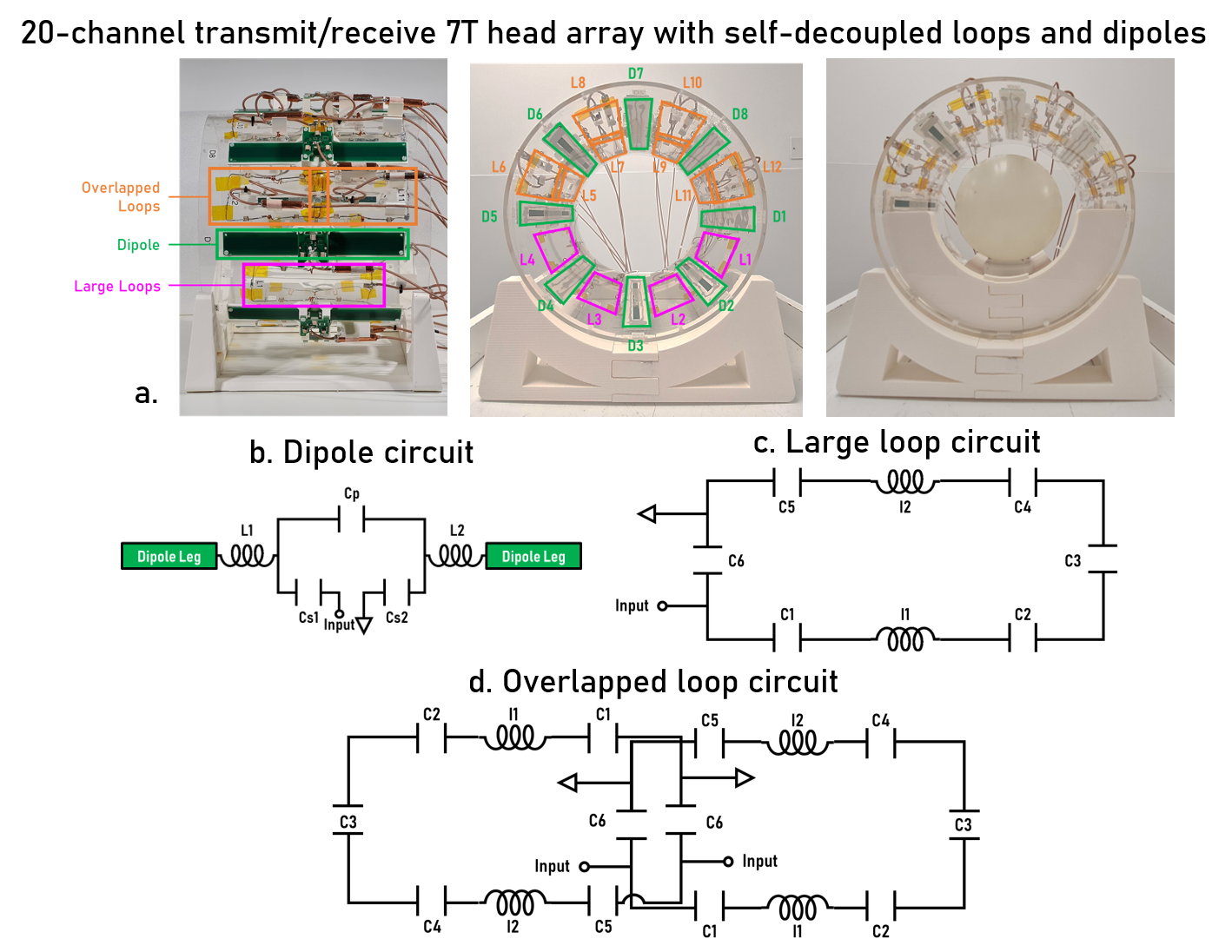
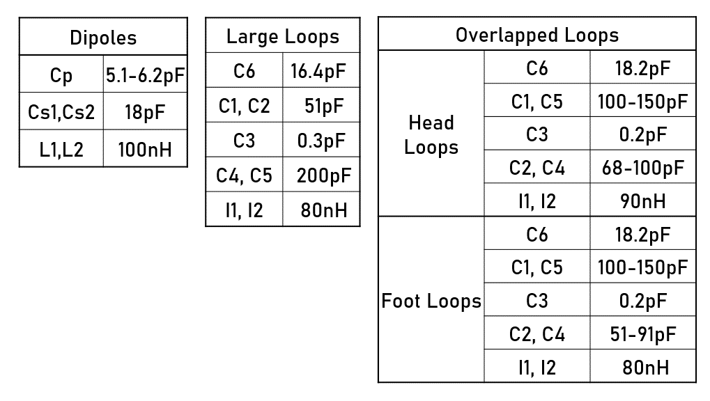
Coil construction: 20 channel head transmit/receive coil array for 7T (297.2 MHz) was designed and built (Figure 1a). The head coil comprises of eight dipoles (Figure 1b), four large self-decoupled loops (Figure 1c) and four pairs of overlapped self-decoupled loop coils (Figure 1d) organised symmetrically around an acrylic cylinder (radius=15cm, height=30cm) resting on custom-built 3D-printed supports (PLA, Ultimaker). The dipoles (170mm×15mm) alternate with each large self-decoupled loop (150mm×60mm) or overlapped loops (120mm×60mm). In-house built baluns tuned to Larmor frequency were placed upon the coaxial cable (K_02252_D,Huber+Suhner,Switzerland) for decoupling. The baluns are stuck to the coil using 3D-printed supports to ensure the orthogonal positioning of the cable relative to the dipole. The overlapped loops were decoupled by adjusting the overlapping area (~10% of loop area). To further decouple the components, cable traps and baluns were placed on each cable connected to loops. The capacitor and inductor values are listed in Figure 2.Bench measurements were taken using a spherical phantom (diameter≈180 mm, Siemens D165-10606820) centred in the coil cylinder using custom-designed 3D-printed supports. S-matrix values were recorded using a VNA (Keysight E5080A ENA, USA) to confirm optimised tuning/matching and decoupling before MRI acquisitions. MRI acquisition was performed on a parallel-transmit 7T MR scanner (MAGNETOM Terra, Siemens Healthineers, Erlangen, Germany) using 8-channel TR switch (MR coiltech, UK) and Siemens phantom. Individual channel B1 maps were obtained from a 2D TFL sequence [7] (TR/TE = 5000ms/2.05ms,FA=5deg, 2.0×2.0x5.0mm3, bandwidth=250Hz/pixel, TA=41s) in three different coil groups of 8-channels.
EM simulations The head coil array was modelled using Sim4Life 7.0 (ZMT AG, Switzerland) tuned to 297.2 MHz and matched to 50 Ohm using co-simulation software (Optenni, Finland) on phantom (permittivity:80, conductivity: 0.5 S/m) and Duke model [8] inside MRI bore shield and simulated using multiport FDTD method. Individual channel B1+ maps were extracted normalised to 1W power. Static RF shim optimisation method [9] was applied to obtained the RF-shimmed B1+ maps on phantoms and Duke head.
Results
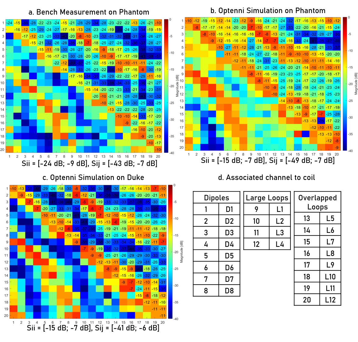
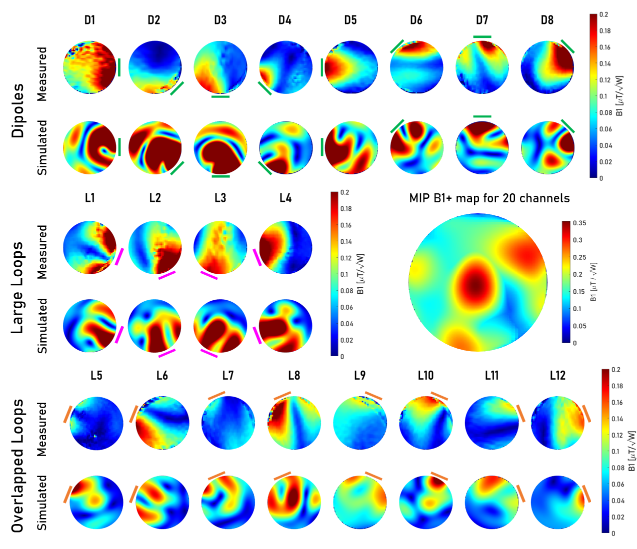
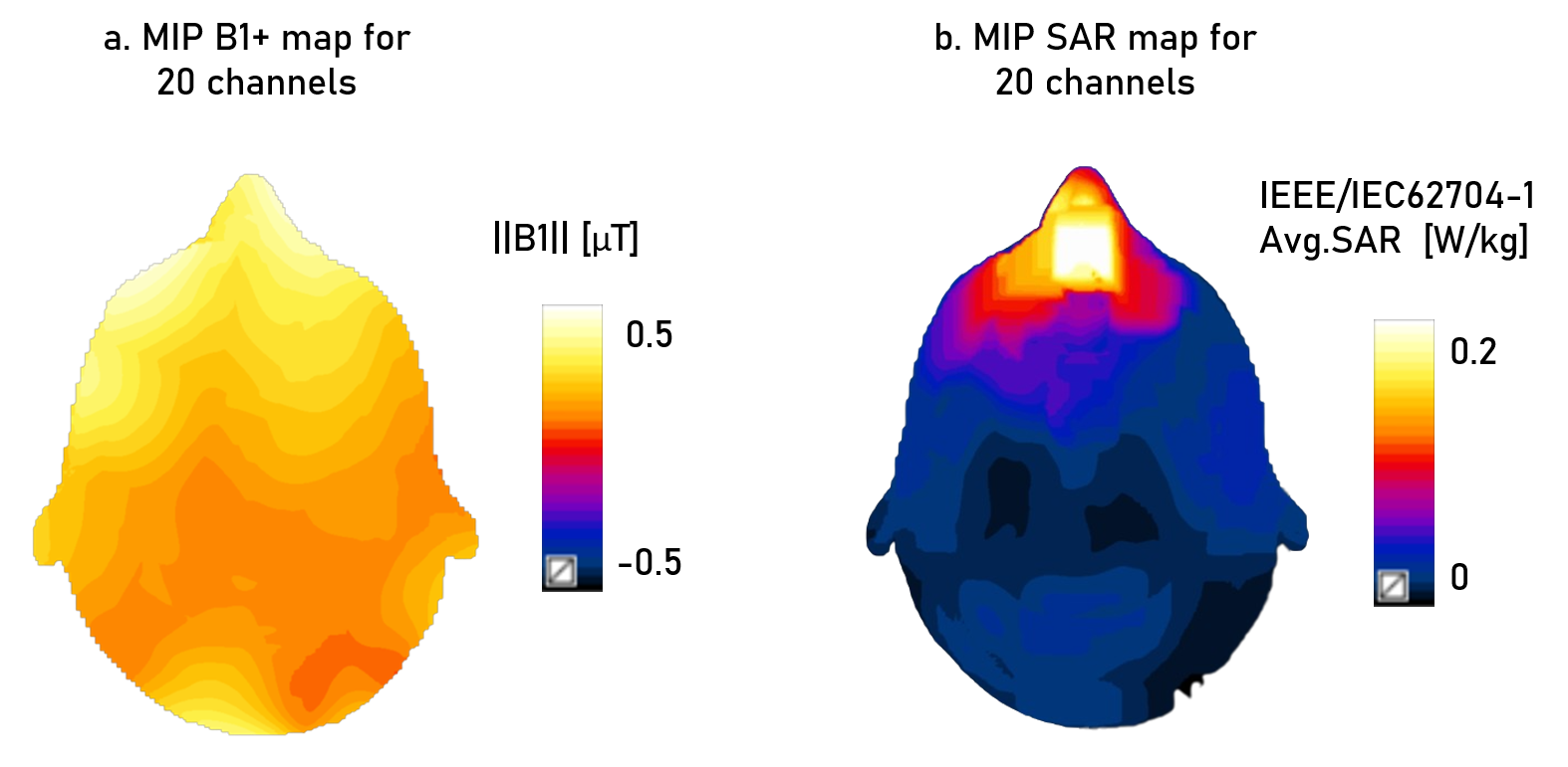
On the bench, the coil array elements were well-tuned and decoupled (Figure 3a). Similar s-matrix results were obtained for phantom and Duke simulations (Figure 3b-c). Individual channel B1+ maps were obtained using MRI measurement and simulations for dipoles, large loops and overlapped loops in 20ch array using phantom: while large loops show efficient B1+ distribution in the measured and simulated maps, dipoles and overlapped loops showed rather less efficient B1+ distribution in the measurement compared to their simulation and dipole results. Static RF shimmed applied on phantom (Figure 4) and on Duke (Figure 5) to obtain shimmed B1+ maps and SAR map using maximum intensity projection.Discussion and conclusion
We showed a successful prototype for robust and dense 20 channel parallel transmit array with dipoles and self-decoupled overlapped loops arrays in alternating design around a cylinder for 7T head MRI. This design will lead to combining parallel imaging with dense and conformal transmit arrays to enable less complex coil arrays in the future.Acknowledgements
This work was supported by core funding from the Wellcome/EPSRC Centre for Medical Engineering [WT203148/Z/16/Z] and by the National Institute for Health Research (NIHR) Biomedical Research Centre based at Guy’s and St Thomas’ NHS Foundation Trust and King’s College London and/or the NIHR Clinical Research Facility. The views expressed are those of the author(s) and not necessarily those of the NHS, the NIHR or the Department of Health and Social Care.References
[1] Yan, X., Gore, J.C. & Grissom, W.A. Self-decoupled radiofrequency coils for magnetic resonance imaging. Nat Commun 9, 3481 (2018). https://doi.org/10.1038/s41467-018-05585-8
[2] Karthik Lakshmanan, Martijn Cloos, Ryan Brown, Riccardo Lattanzi, Daniel K. Sodickson, Graham C. Wiggins, "The “Loopole” Antenna: A Hybrid Coil Combining Loop and Electric Dipole Properties for Ultra-High-Field MRI", Concepts in Magnetic Resonance Part B, Magnetic Resonance Engineering, vol. 2020, Article ID 8886543, 9 pages, 2020. https://doi.org/10.1155/2020/8886543
[3] Avdievich, NI, Nikulin, AV, Ruhm, L, Magill, AW, Henning, A, Scheffler, K. Double-row dipole/loop combined array for human whole brain imaging at 7 T. NMR in Biomedicine. 2022; 35(10):e4773. doi:10.1002/nbm.4773
[4] Shajan G, Kozlov M, Hoffmann J, Turner R, Scheffler K, Pohmann R. A 16-channel dual-row transmit array in combination with a 31-element receive array for human brain imaging at 9.4 T. Magn Reson Med. 2014; 71(2): 870-879. doi:10.1002/mrm.24726
[5] Adriany G, Van de Moortele PF, Ritter J, et al. A geometrically adjustable 16-channel transmit/receive transmission line array for improved RF efficiency and parallel imaging performance at 7 Tesla. Magn Reson Med. 2008; 59(3): 590-597. doi:10.1002/mrm.21488
[6] Gilbert KM, Belliveau JG, Curtis AT, Gati JS, Klassen LM, Menon RS. A conformal transceive array for 7 T neuroimaging. Magn Reson Med. 2012; 67(5): 1487-1496. doi:10.1002/mrm.23124
[7] Bottomley PA, Ouwerkerk R. The Dual-Angle Method for Fast, Sensitive T1 Measurement in Vivo with Low-Angle Adiabatic Pulses. J Magn Reson B. 1994 Jun 1;104(2):159–67.
[8] Gosselin MC, Neufeld E, Moser H, Huber E, Farcito S, Gerber L, Jedensjö M, Hilber I, Di Gennaro F, Lloyd B, Cherubini E, Szczerba D, Kainz W, Kuster N. Development of a new generation of high-resolution anatomical models for medical device evaluation: the Virtual Population 3.0. Phys Med Biol. 2014;59(18):5287-5303. doi:10.1088/0031-9155/59/18/5287.
[9] Clément J, Tomi-Tricot R, Malik SJ, et al. Towards an integrated neonatal brain and cardiac examination capability at 7 T: electromagnetic field simulations and early phantom experiments using an 8-channel dipole array. Magn Reson Mater Phy. 2022;35(5):765-778. doi:10.1007/s10334-021-00988-z.
Figures