0464
Using Inductively-Coupled Dipole Pairs as Array Elements for Improving Whole-Brain Coverage at 9.4T1School of Physics and Engineering, ITMO University, St. Petersburg, Russian Federation, 2High-Field MR Center, Max Planck Institute for Biological Cybernetics, Tübingen, Germany
Synopsis
Keywords: RF Arrays & Systems, Brain, Array, UHF, dipole, coverage
Motivation: At ultra-high fields, homogeneity of brain MRI is deteriorated by the subject-specific non-uniform distribution of RF magnetic field B1+.
Goal(s): To design a 9.4T eight-channel transceiver dipole array with improved homogeneity of B1+ in the axial direction with better whole-brain coverage.
Approach: We used an array consisting of paired passively coupled folded-end dipoles. We numerically optimized the B1+ homogeneity by adjusting the overlap between the folded ends of the active and passive dipoles and the load impedance of the passive one.
Results: The proposed array demonstrated improved B1+ whole-brain homogeneity including the upper C-spine compared to several state-of-the-art dipole and loop arrays.
Impact: The presented antenna element of coupled folded dipoles can be used in designing UHF array coils with improved longitudinal whole-brain coverage. Such coils can be beneficial for studies where imaging of the entire brain including the upper C-spine is required.
Introduction
Several designs of human head arrays have been proposed recently for ultra-high field (UHF, > 7T) magnetic resonance imaging (MRI). At 9.4T, whole-brain coverage can be achieved by using dual-row transceiver (1) or transmit (2) loop arrays combined with 3D static (3) or dynamic (4) RF shimming. However, such arrays are rather complicated to construct and require many (more than ten per loop) high-power capacitors distributed along the loop’s conductors. As an alternative approach, dipole antenna arrays (5,6,7) can be used. Dipole arrays usually do not require decoupling and are much simpler to construct compared to loop arrays. Recently, a dual-row 16-channel folded-end dipole antenna array with 3D RF shimming capability was proposed (8). However, currently the majority of UHF MRI scanners are equipped with only 8 high-power transmit channels. In this work, we proposed and numerically optimized an array of 8 actively driven plus 8 passively coupled folded dipoles capable of increasing the longitudinal coverage inside the human brain and upper C-spine while using 8 transmit channels.Methods
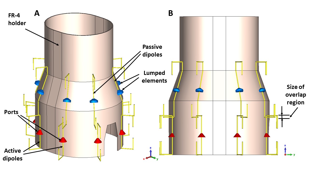
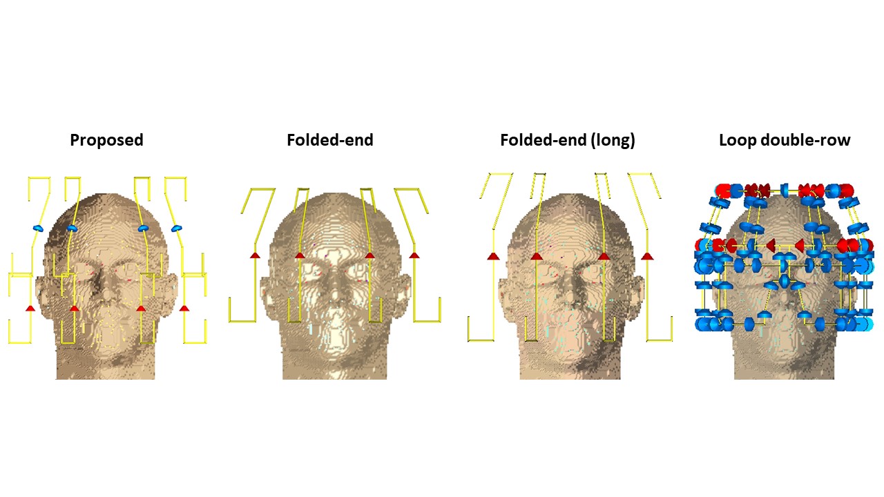
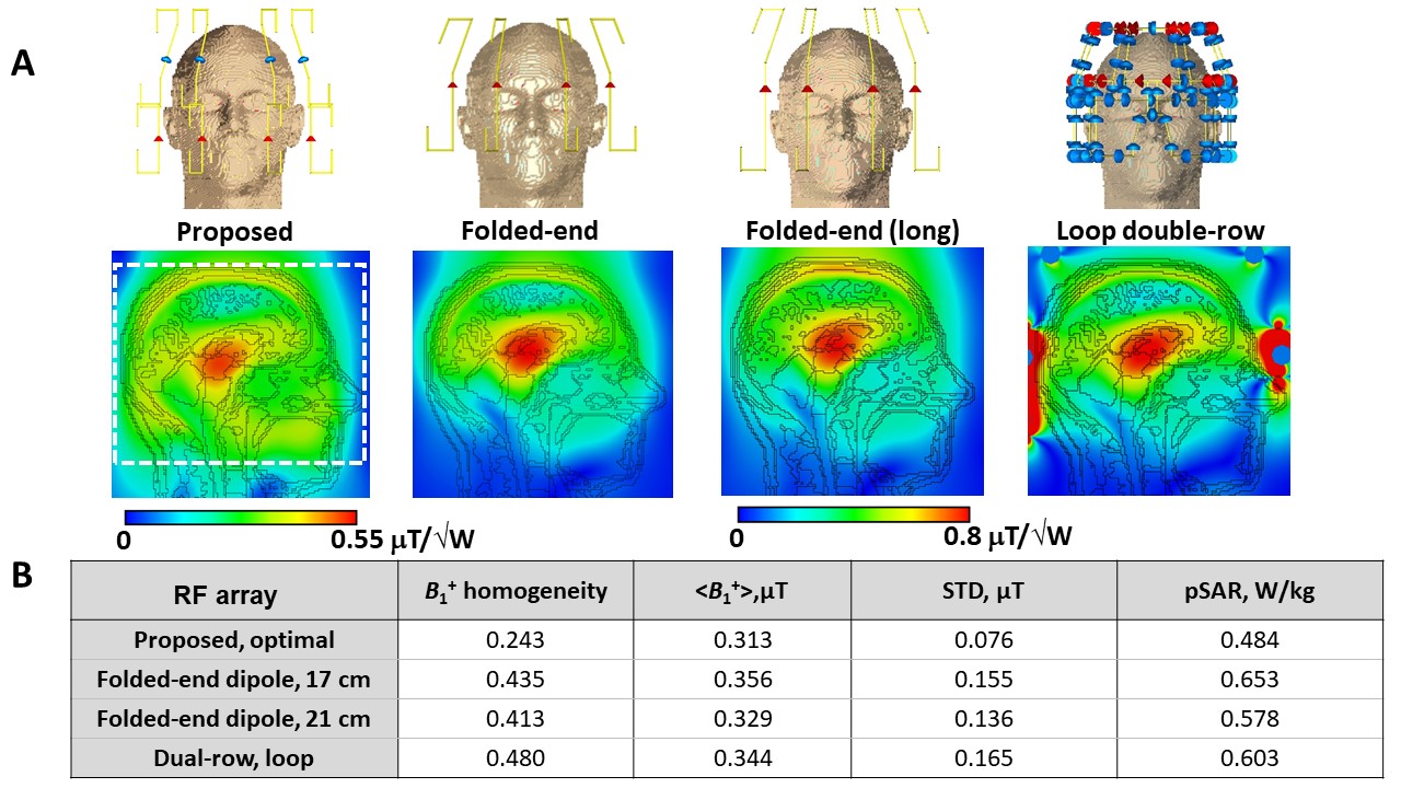
Each composite element of the array consisted of a pair of a passive (superior) and active (inferior) folded-end dipoles placed on the surface of an FR-4 elliptical cylindrical holder (Figure 1). To control the phase and magnitude of the current induced in the passive dipole relative to the active one, different overlapping lengths between the two dipoles and different load reactance (Xp) connected in the middle of the passive dipole were systematically compared. The proposed array was numerically simulated using the finite time domain integration method implemented in the CST Microwave Studio 2021 (Dassault Systèmes, Vélizy-Villacoublay, France). RF magnetic field, B1+, was calculated for the circularly polarized (CP) mode (the phase shift between neighboring elements was 45◦). SAR was evaluated using the CST Legacy averaging method. Duke and Ella multi-tissue voxel models were used in simulations. The array design was optimized by changing the dipole length, overlapping length, and complex impedance of the lumped loads, Xp. From numerical optimization, we found the optimal array configuration with the best B1+ homogeneity. B1+ field homogeneity was evaluated as the ratio between the standard deviation (STD) and mean value over the 190-mm transversal slab, which included the whole brain and upper C-spine. SAR10g (8) also was calculated. For comparison, we also numerically evaluated the performance of several arrays including eight-channel 17-cm (6) and 21-cm folded-end dipole arrays, and 16-channel double-row loop array (2). Figure 2 presents numerical models of all simulated array coils.Results and Discussion
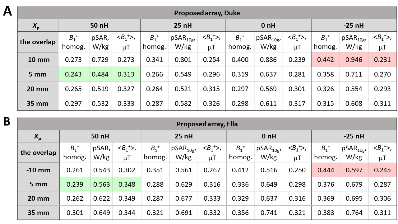
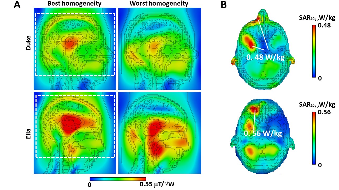
Figure 3 shows optimization results of the proposed array including the B1+ homogeneity, average <B1+>, and pSAR calculated for different overlap lengths and Xp values. As seen in the table, the array with Xp = 50 nH and the overlap length of 5 mm provides the best compromise between the homogeneity and pSAR level. Figure 4A presents B1+ in the central sagittal plane of Duke and Ella voxel models obtained using the best and worst dual-dipole arrays configurations. Figure 5A shows numerically simulated B1+ in the central sagittal slice of the Duke voxel model using the optimal configuration (5-mm overlap, Xp=50 nH) of the dual-dipole array, 17-cm and 21-cm folded-end dipole arrays, and dual-row loop array. Figure 4B also presents transversal SAR10g maps cut through the maximum SAR locations (pSAR values are indicated). Figure 5B presents simulation results for all four arrays including the B1+ homogeneity, average <B1+>, STD, and pSAR10g values. As seen in Figures 5A and 5B, the proposed array substantially improves the coverage compared to all other considered arrays. Importantly, the proposed array provides coverage of the whole brain and the upper part of the spinal cord. Furthermore, the pSAR10g value of the optimal dipole array is lower than that of other simulated arrays.Conclusion
We numerically optimized and numerically studied a novel RF 8-channel dipole array for human head MRI at 9.4T. The array geometry is based on composite elements consisting of paired folded-end dipoles with inductive coupling. The proposed array provides substantially better B1+ homogeneity and longitudinal coverage as well as lower pSAR compared to other state-of-the-art dipole and loop arrays. The proposed array can be used for UHF applications where the whole-brain and the upper C-spine coverage is required.Acknowledgements
This work was performed with financial support of the Russian Science Foundation (Project No. 21-79-30038).References
- G. Shajan, M. Kozlov, J. Hoffmann, R. Turner, K. Scheffler, and R. Pohmann, "A 16-channel dual-row transmit array in combination with a 31-element receive array for human brain imaging at 9.4 T," Magnetic resonance in medicine, vol. 71, pp. 870-879, February 2014.
- N. Avdievich, I. Giapitzakis, A. Pfrommer, G. Shajan, K. Scheffler, and A. Henning, "Decoupling of a double‐row 16‐element tight‐fit transceiver phased array for human whole‐brain imaging at 9.4 T," NMR in Biomedicine, vol. 31, pp. 3964, September 2018.
- W. Mao, M. Smith, and C. Collins, "Exploring the limits of RF shimming for high-field MRI of the human head, " Magnetic resonance in medicine, vol. 56, pp. 918-922, October 2006.
- H. Matthijs, J. Kent, P. Jezzard, and A. Hess, " Head-and-neck multichannel B1+ mapping and RF shimming of the carotid arteries using a 7T parallel-transmit head coil," Magnetic resonance in medicine, pp. 1-15, August 2023.
- J. Clement, R. Gruetter, and O. Ipek, "A combined 32‐channel receive‐loops/8‐channel transmit‐dipoles coil array for whole‐brain MR imaging at 7T," Magnetic resonance in medicine, vol. 82, pp. 1229-1241, May 2019.
- N. Avdievich, G. Solomakha, L. Ruhm, A. Henning, and K. Scheffler, "Unshielded bent folded‐end dipole 9.4 T human head transceiver array decoupled using modified passive dipoles," Magnetic resonance in medicine, vol. 86, pp. 581-597, February 2021.
- N. Avdievich, G. Solomakha, L. Ruhm, A. Nikulin, A. Magill, and K. Scheffler, “Folded‐end dipole transceiver array for human whole‐brain imaging at 7 T,” NMR in Biomedicine, vol 34, e4541, May 2021.
- A. Nikulin, D. Bosch, G. Solomakha, F. Glang, K. Scheffler, and N. Avdievich, "Double‐row 16‐element folded‐end dipole transceiver array for 3D RF shimming of the whole human brain at 9.4 T, " NMR in Biomedicine, vol. 36, e4981, October 2023.
Figures