0152
A MR Fingerprinting Development Kit (MRFDK) for Quantitative 3D Brain Imaging1Radiology, Case Western Reserve University, Cleveland, OH, United States, 2Siemens Healthineers AG, Erlangen, Germany, 3Siemens Medical Solutions USA, Boston, MA, United States, 4Biomedical Engineering, Case Western Reserve University, Cleveland, OH, United States
Synopsis
Keywords: MR Fingerprinting, MR Fingerprinting
Motivation: MRF acquisitions rely on offline reconstructions due to their computationally intensive processing pipelines which hinders integration into clinical workflows.
Goal(s): To introduce and test a development kit for MRF, enabling 1) efficient whole brain 3D MRF acquisitions, 2) embedded dictionary calculation, and 3) rapid online post-processing.
Approach: The method was evaluated with phantom and in vivo brain imaging for multiple MRF variants and receive coils.
Results: Due to full scanner integration, high-quality T1 and T2 maps were presented on the host computer within 1 min after the MRF scan was completed, enabling timely visualization of the outcome.
Impact: The MRF development kit has high potential to promote reproducibility, large-scale clinical evaluation and translation of the novel MRF technique.
Introduction
MR Fingerprinting (MRF) is a rapidly developing quantitative imaging framework that enables simultaneous measurement of several important tissue parameters in a single MRI scan (1). The development and implementation of MRF is technically challenging, which requires advanced pulse sequence programming, MRF dictionary simulation, and tissue property mapping. Compared to conventional MR imaging, the post-processing of MRF is computationally intensive due to the need for non-Cartesian reconstruction of thousands of images and pattern matching based on a large MRF dictionary for millions of voxels. This posts particular challenges for volumetric imaging, for example, high-resolution whole brain imaging. Thus, MRF post-processing for the majority of studies is conducted offline, hindering prompt visualization of acquired results and integration with standard clinical workflow. In this study, with joint efforts from both the industry and our academic institute, we aim to further develop and validate a modular MRF Development Kit (MRFDK) (5) for rapid and efficient MRF prototyping to achieve 1) efficient 3D MRF acquisitions with whole brain coverage, 2) embedded MRF dictionary calculation, and 3) full scanner integration allowing rapid online MRF post-processing to promote large-scale clinical evaluation and translation for this new quantitative imaging technique.Methods
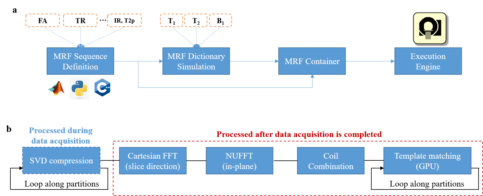
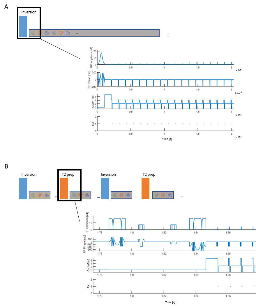
An MRF sequence definition file was first generated (Fig 1), which can be conducted using different development environments (e.g., C++, MATLAB, python). The user, based on their programming environment choice, fully defines the RF amplitudes and pulse shapes, gradient moments and echo positions, in combination with the MRF acquisition pattern (FA, TR, etc.). Bloch simulation was further performed to generate the corresponding MRF dictionary based on the sequence definition file and pre-defined tissue property values (1). Signal simulation with acquisition modules such as inversion recovery and T2-preparation modules were also implemented along with the extra dimension of B1 field (6). Based on the MRF sequence definition and dictionary, a single file called MRF container was generated and copied to the MRI scanner for direct MRF measurement. An MRF execution engine was installed on the scanner to interpret the MRF container. The MRF execution engine can pick from a list of MRF containers so different studies with various MRF acquisition protocols can be deployed together. The MRFDK also provides rapid online reconstruction for 3D MRF (Fig 1b). Singular value decomposition (SVD) was first performed to accelerate data processing (7).We applied the MRFDK framework to an established 3D MRF protocol for neuroimaging (Figure 2a) on a MAGNETOM VIDA scanner (Siemens Healthineers AG, Erlangen, Germany) (8). An interleaved undersampling (R=2) along slice-encoding direction was also implemented and the 3D MRF scan with whole brain coverage was ~6 min. A B1 mapping acquisition of ~20 sec was applied before the MRF acquisition to provide optional B1 correction. All the MRF maps were obtained during online reconstruction. The accuracy of MRFDK was validated in NIST phantom experiments and the method was further applied for in vivo brain imaging. To demonstrate the versatility of MRFDK, another 3D MRF protocol using IR/T2-preparation modules and golden-angle spiral encoding (Figure 2b) was also implemented with the same spatial resolution. (9).
Results
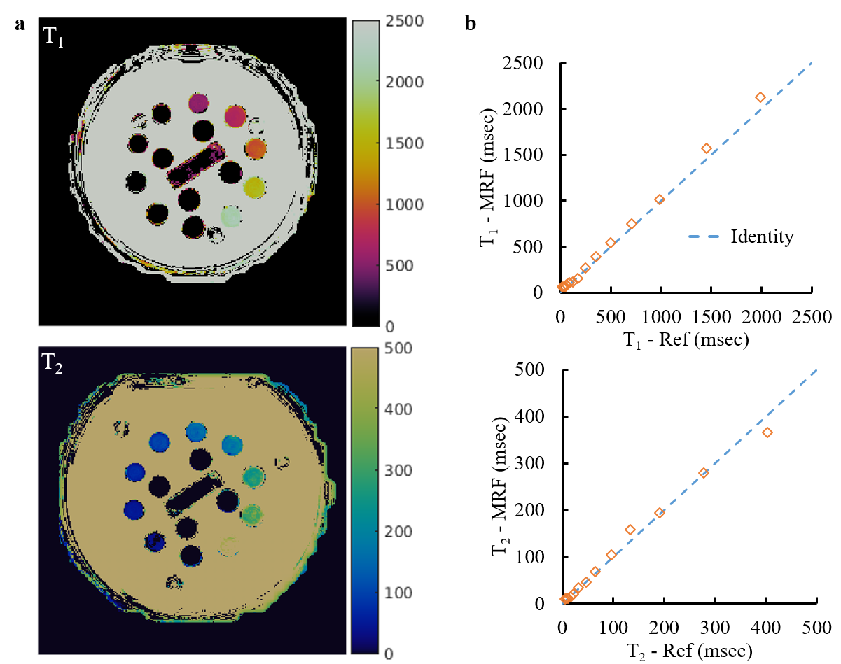
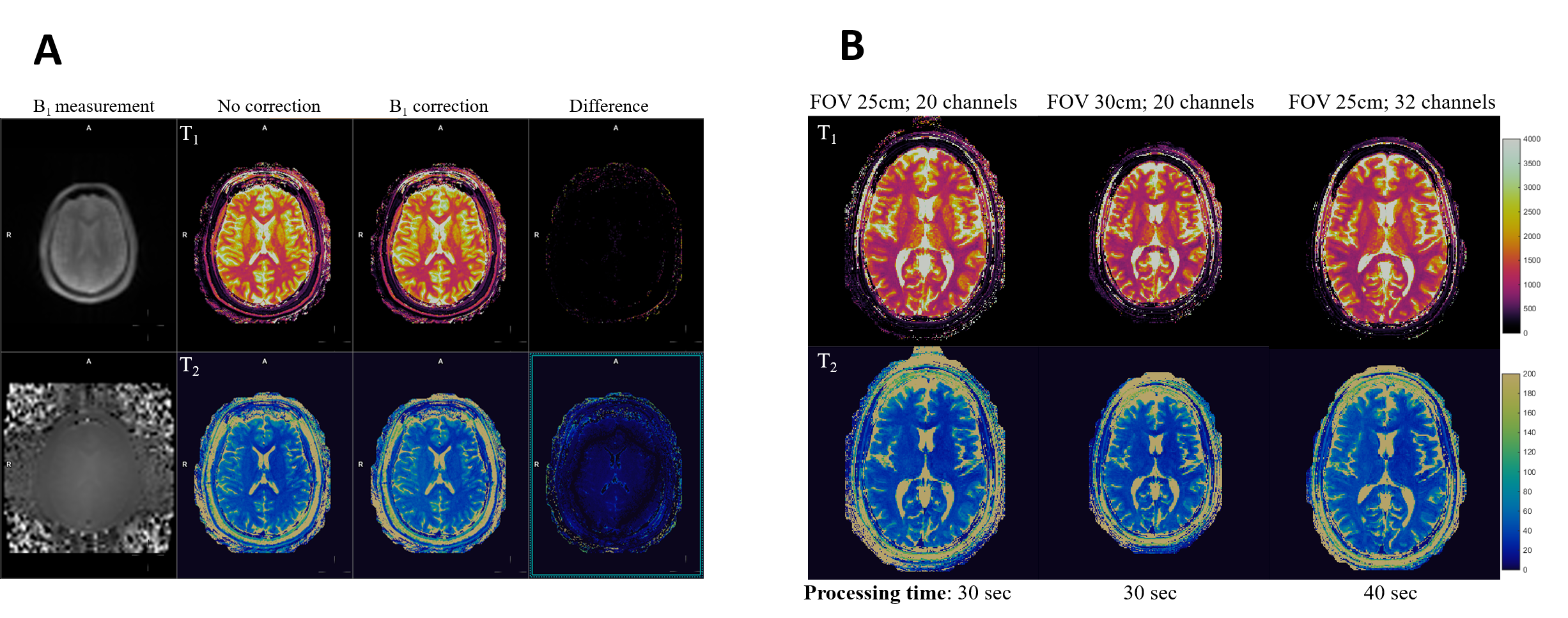
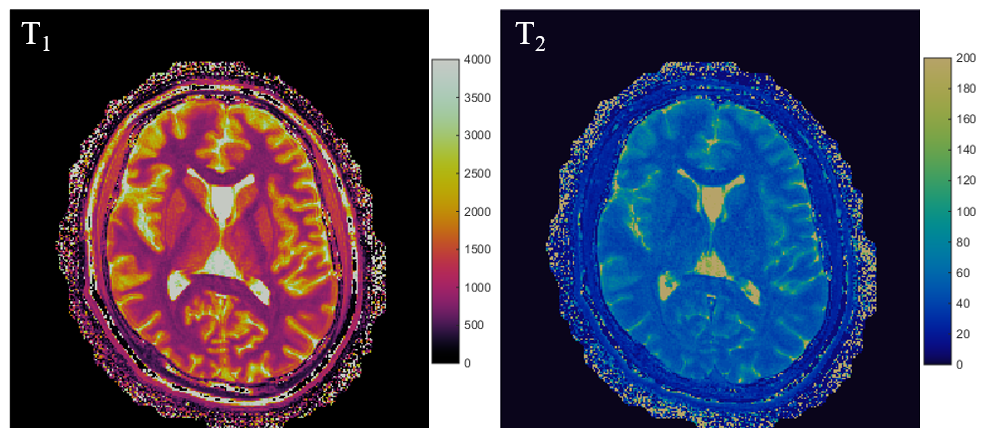
The NIST phantom experiment shows that quantitative T1 and T2 assessment acquired using MRFDK agrees well with the reference values provided by NIST (Fig 3). Fig 4a shows MRFDK provided high-quality MRF tissue maps and a more uniform T2 map after B1 correction. MRFDK is built upon the vendor spiral framework and the spiral trajectory is calculated based on the specified FOV and matrix size on the fly, including critical corrections such as scanner individual gradient delays. Figure 4b presents MRF T1 and T2 maps obtained from the same subject with two different FOVs. With a 20-channel head/neck coil, all the tissue property maps were available for visualization on the host computer 30 sec after the scan was completed, enabling timely checking of the results. The processing time increased by 10 s when switching to a 32-channel head coil (Fig 4b). Finally, another MRF container based on IR/T2-preparation modules and golden-angle spiral trajectories was also generated based on the MRFDK framework, yielding high-quality T1 and T2 maps for in vivo brain imaging (Fig 5).Discussion and Conclusion
In this study, we introduced and evaluated the MRFDK framework for efficient 3D brain MRF acquisition and rapid online reconstruction. All the phantom and in vivo MRF maps were obtained from online reconstruction without any additional offline processing. In the future, more advanced tissue analysis leveraging the quantitative tissue property maps, such as partial volume analysis (10), will be implemented to provide more comprehensive tissue characterization.Acknowledgements
Siemens Healthineers and NIH grants 1R01 CA266702, and 1R01 CA282516.
References
1. Ma D, et al. Nature, 2013; 187–192.
2. Badve C, et al. ASNR, 2017; 492-499.
3. Yu AC, et al. Radiology, 2017; 729-738.
4. Ma D, et al. JMRI, 2019; 1333-1346.
5. Kluge et al. ISMRM 2022, 4798
6. Chen Y, et al. Radiology, 2016; 278-286.
7. McGivney D, et al. TMI, 2014; 2311-2322.
8. Dupuis A, et al. ISMRM, 2022, 422.
9. Chen Y, et al. NeuroImage, 2020, 116329.
10. Deshmane A, et al. NMR Biomed, 2019, e4082.
Figures