0004
Any-nucleus Distributed Active Programmable Transmit Coil1University of California, Berkeley, Berkeley, CA, United States
Synopsis
Keywords: Non-Array RF Coils, Antennas & Waveguides, Non-Proton, Multinuclear, RF coil, X-nuclei
Motivation: There are 118 elements. Nearly all elements have NMR active isotopes and 39 different nuclei have been shown to have biological relevance. Despite this, most of today’s MRI is based on only one nucleus – 1H.
Goal(s): To significantly reduce the cost and complexity of imaging all potential nuclei.
Approach: We present the Any-nucleus Distributed Active Programmable Transmit Coil (ADAPT Coil), with fast switches integrated into the coil itself which allows it to selectively excite any nucleus using digital controls.
Results: Using the ADAPT Coil, we acquired 1H, 23Na, 2H, and 13C phantom images and 1H and 23Na ex vivo images at 3T.
Impact: The ADAPT Coil enables arbitrary nucleus excitation in high field MRI, significantly reducing the cost and technological barriers of clinical translation of X-nuclei research. X-nuclei benefits include improved early diagnosis and treatment evaluation for cancer, osteoarthritis, Alzheimer’s, and many more.
Introduction
There are 118 known elements. Nearly all of them have NMR active isotopes and at least 39 different nuclei from 33 different elements have been used in biological and biomedical NMR studies1. Despite the availability of dozens of NMR active isotopes, most of today’s MRI is based on only one nucleus – 1H. Although various technological advances have made the imaging of nuclei other than 1H, or X-nuclei, more clinically feasible, the proliferation of these studies is still held back by the low availability of the tools able to perform them. Whenever an X-nucleus is to be studied, a heavy investment is needed to obtain additional expensive MRI hardware (e.g. RF amplifier, coils, and receiver chains) to enable imaging of the specific nucleus of interest. Here, we present the Any-nucleus Distributed Active Programmable Transmit Coil (ADAPT Coil), an inexpensive and untuned, yet scalable, coil capable of efficiently transmitting at arbitrary frequencies using a unique architecture composed of many high-frequency semiconductor power switches integrated directly into the coil structure. By doing so, the coil and RF amplifier are merged into a single device that directly converts DC power into RF fields at any relevant frequency. On the receive side, we use several single-tuned receive coils to demonstrate the capabilities of our transmit coil. A corresponding arbitrary-frequency receive coil is under development and is the subject of future publications.Theory and Methods
Resonant coils are severely limited in their bandwidth. So, to make an arbitrary nucleus transmit coil, our approach applies voltage directly to an untuned coil. This approach mirrors that taken by Mandal et al. and Hopper et al.2–4 in their low-frequency NMR system covering up to 3 MHz. Their approach, however, is limited by the voltage and speed capabilities of the semiconductors used. Our approach enables the direct application of voltage across a coil without being limited by the semiconductor voltage capabilities, thus enabling the use of faster devices. To do this, we draw inspiration from the distributed active transformer5 in the integrated circuits literature, which addresses a similar problem of generating higher output voltages from low-voltage CMOS transistors by placing several transistors in a loop. Figure 1a-c shows the most basic case where switches alternating at the RF frequency change the current path of a DC voltage source, thus generating RF currents. Instead of breaking the coil into two halves, we can continue to break it up into smaller pieces, each with a pair of out-of-phase switches connected to the negative terminal of the DC voltage source (Figure 1d-f). Now the same voltage source drives several smaller inductances (coil segments) in parallel and thus can produce larger RF currents. These RF currents together then produce larger magnetic fields than what one set of switches could produce alone.The coil architecture was implemented using commercial parts assembled on a four-layer FR4 printed circuit board (PCB). Figure 2 shows a block diagram of the coil and its operation. The RF magnetic field produced by the ADAPT Coil was measured on the benchtop, and both phantom and ex vivo X-nuclei images were taken using the same ADAPT Coil by simply changing the control signals for transmit. Multiple single-tuned receive coils were used.
Results
Figure 3 shows the fabricated coil and some magnetic field measurements at many frequencies 19.6 mm away from the center of the coil.Figure 4 shows GRE images of a bottle and tube phantom with 1H (Figure 4a), 23Na (Figure 4b), 2H (Figure 4c), and 13C (Figure 4d). The images are overlaid in Figure 4e, a labeled optical image of the phantom is shown in Figure 4f, and an illustration of the phantom is shown in Figure 4g.
Figure 5 shows 1H and 23Na GRE images of a bone-in ham steak (Figure 5ab) and a pig knee (Figure 5de). Optical images of the ham steak (Figure 5c) and the pig knee (Figure 5f) are also shown.
Discussion and Conclusion
We present the ADAPT Coil, a scalable and inexpensive method of building arbitrary nucleus transmit coils for high-field, human-scale MRI. The parts on this coil prototype cost less than $116. To cover more anatomy, a transmit coil array can be made using the surface coil presented here. Even without being paired with an arbitrary-nucleus receive coil, the ADAPT Coil provides many benefits by itself, such as enabling polarization transfer between X-nuclei and 1H and being reusable between scanners of different field strengths. With at least 39 biologically-relevant nuclei1, we believe the capability to obtain signal from arbitrary X-nuclei can revolutionize the use of magnetic resonance in medicine.Acknowledgements
The authors thank Karthik Gopalan and Anita Flynn for teaching RF coil basics many years ago, Prof. Miki Lustig and Julian Maravilla for resource support and advice, Prof. Robert Pilawa-Podgurski for teaching classes on Power Electronics, Prof. Ali Niknejad for teaching classes on integrated circuits for communications, Prof. Peder Larson and Xiaoxi Liu for the 13C sample, Lucas Carvajal for a tour of a 13C setup, and Katie Larmar for help with HeartVista.
Financial Interest Disclosure
VH and CL are inventors on a patent application
related to the ADAPT Coil filed by the University of California.
References
1. Patching SG. NMR-active nuclei for biological and biomedical applications. Journal of Diagnostic Imaging in Therapy. 2016;3(1):7-48.
2. Mandal S, Utsuzawa S, Cory DG, Hürlimann M, Poitzsch M, Song YQ. An ultra-broadband low-frequency magnetic resonance system. Journal of Magnetic Resonance. 2014;242:113-125. doi:10.1016/j.jmr.2014.02.019
3. Hopper T, Mandal S, Cory D, Hürlimann M, Song YQ. Low-frequency NMR with a non-resonant circuit. Journal of Magnetic Resonance. 2011;210(1):69-74. doi:10.1016/j.jmr.2011.02.014
4. Mandal S, Utsuzawa S, Song YQ. An extremely broadband low-frequency MR system. Microporous and Mesoporous Materials. 2013;178:53-55. doi:10.1016/j.micromeso.2013.03.040
5. Aoki I, Kee SD, Rutledge DB, Hajimiri A. Distributed active transformer-a new power-combining and impedance-transformation technique. IEEE Transactions on Microwave Theory and Techniques. 2002;50(1):316-331. doi:10.1109/22.981284
Figures
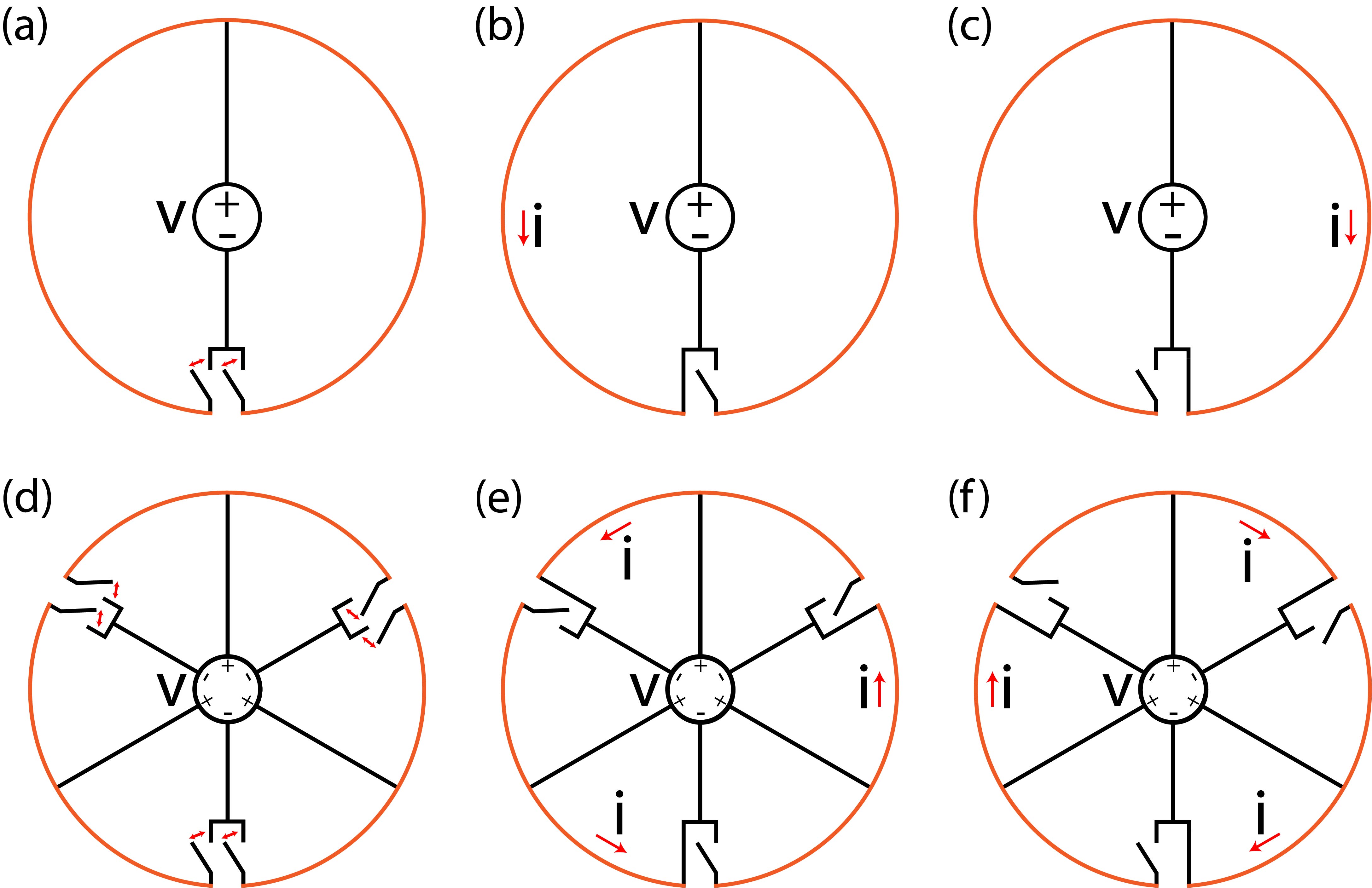
Figure 1 – ADAPT Coil Concept
(a-c) The base configuration of an ADAPT Coil splits the coil in half and uses two switches to connect a DC voltage source across each half in an alternating manner. By changing the connections, AC current is produced in the coil. (d-f) The ADAPT Coil can be further split in a scalable manner by adding more switches and connections to the DC voltage source. By splitting the coil into smaller segments, the same voltage from the voltage source can drive more current through the coil segment inductances without adding more voltage stress to the switches.
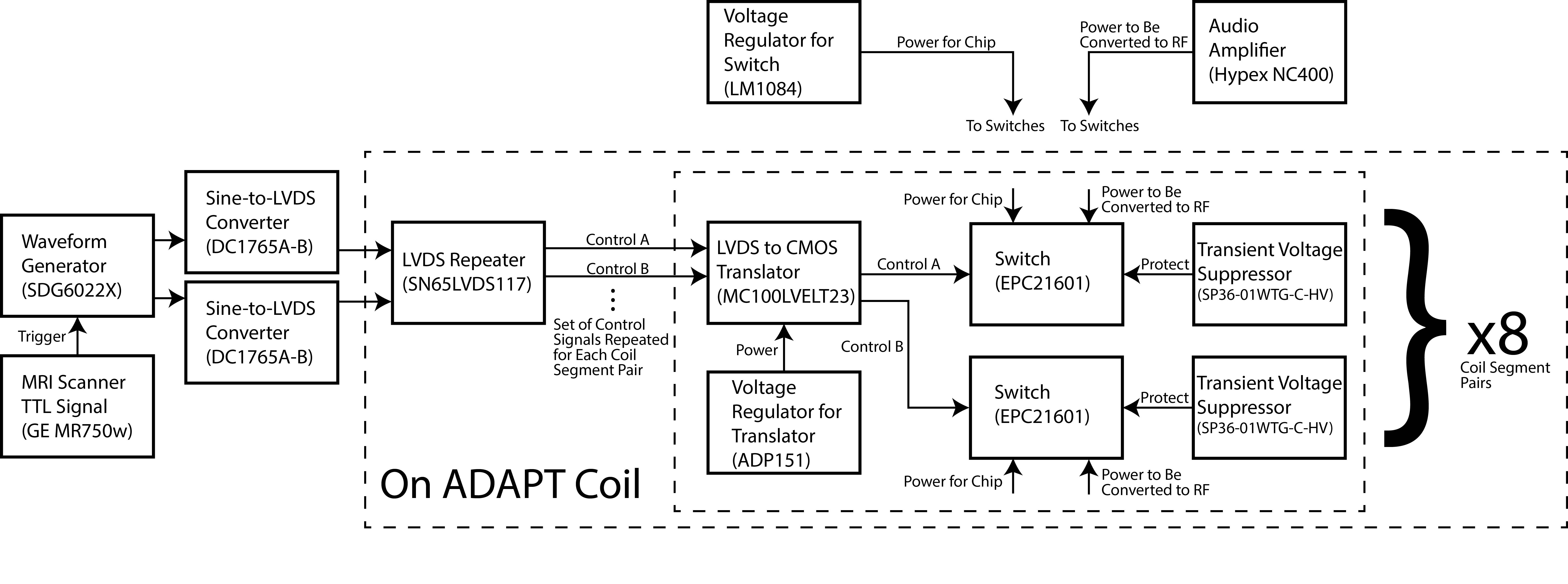
Figure 2 – Block Diagram of ADAPT Coil Chips and MRI Setup
The MRI scanner triggers a waveform generator to produce two out-of-phase sinewaves. These sinewaves are converted to low voltage differential signaling (LVDS) digital signals and then sent to the ADAPT Coil. On the ADAPT Coil, a LVDS repeater copies the control signals to each pair of coil segments. At each coil segment, the LVDS is converted to CMOS, which then drives the switches. The switching frequency sets the RF frequency. A DC-coupled audio amplifier provides the DC voltage whose power gets converted to RF by the switching.
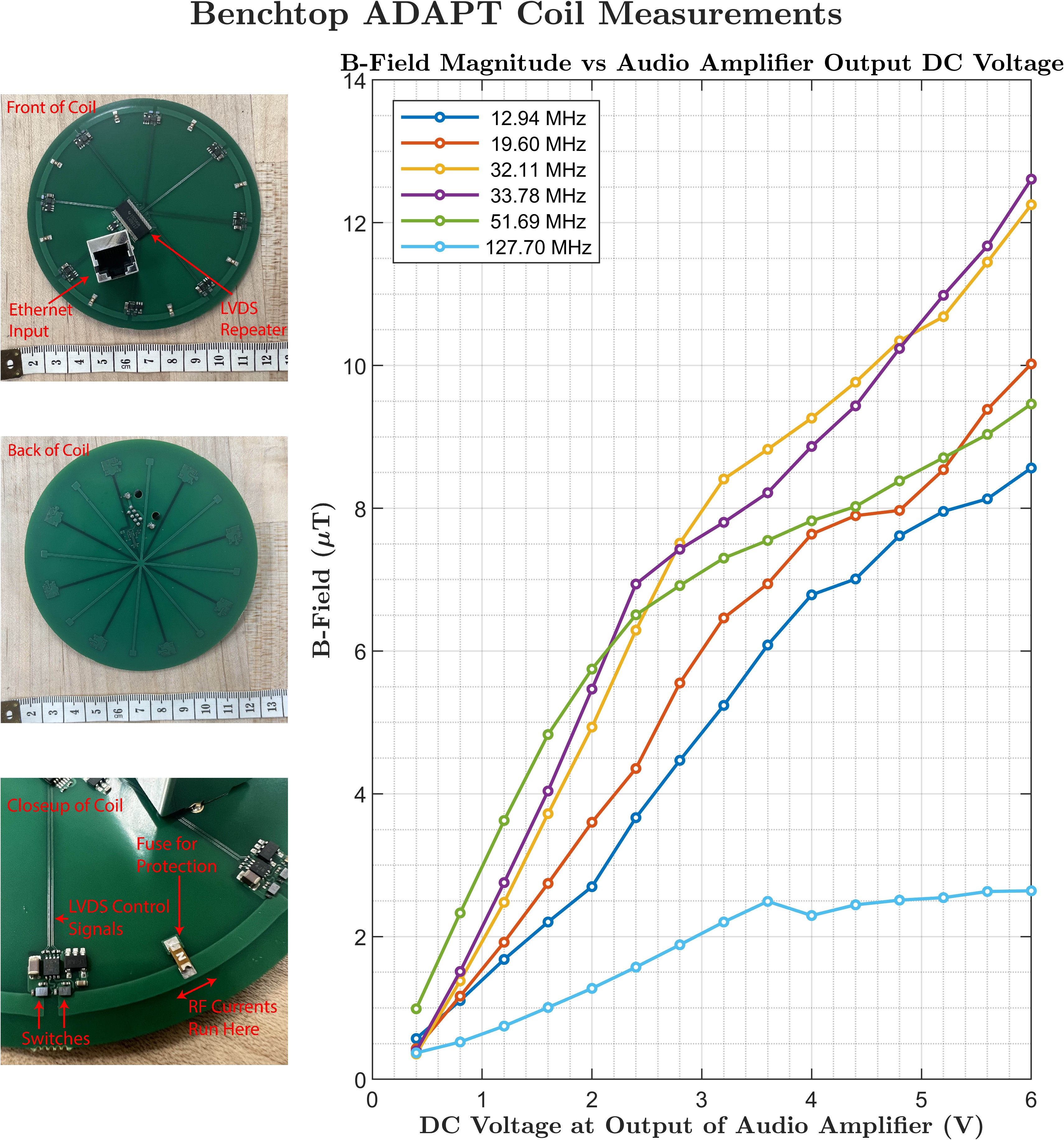
Figure 3 – Benchtop ADAPT Coil DC Voltage Sweep
In the fabricated ADAPT Coil, the eight coil segment pairs are symmetrically arranged in a circle with a 9 cm diameter. The LVDS repeater chip is at the center and the LVDS control signals and power are delivered via an ethernet cable. RF magnetic field measurements taken 19.6 mm away from the center of the back of the coil are shown for several frequencies and a range of DC voltages from a DC-coupled audio amplifier used as an input to the ADAPT Coil. Control frequencies were changed to change the RF frequency that the DC voltage was converted to.
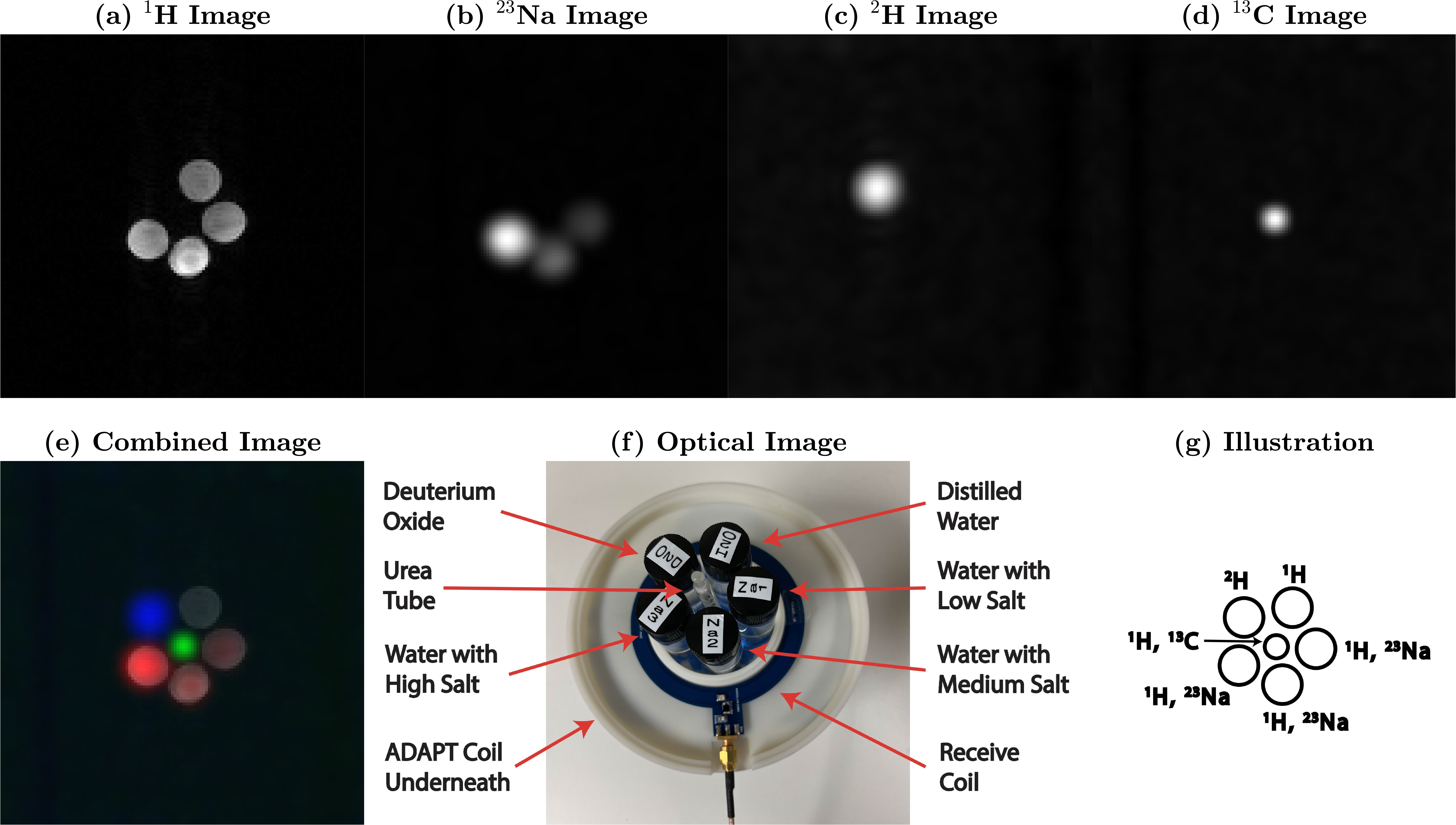
Figure 4 – Phantom 1H, 23Na, 2H, and 13C Magnetic Resonance Images Using the ADAPT Coil
Magnetic resonance images of the bottle and tube phantom with 1H (a), 23Na (b), 2H (c), and 13C (d) imaging. The images are overlaid in (e), a labeled optical image of the phantom is shown in (f), and an illustration of the phantom is shown in (g). The 1H signal from the urea tube is not readily visible in (a) compared to the other 1H sources for these sequence parameters.
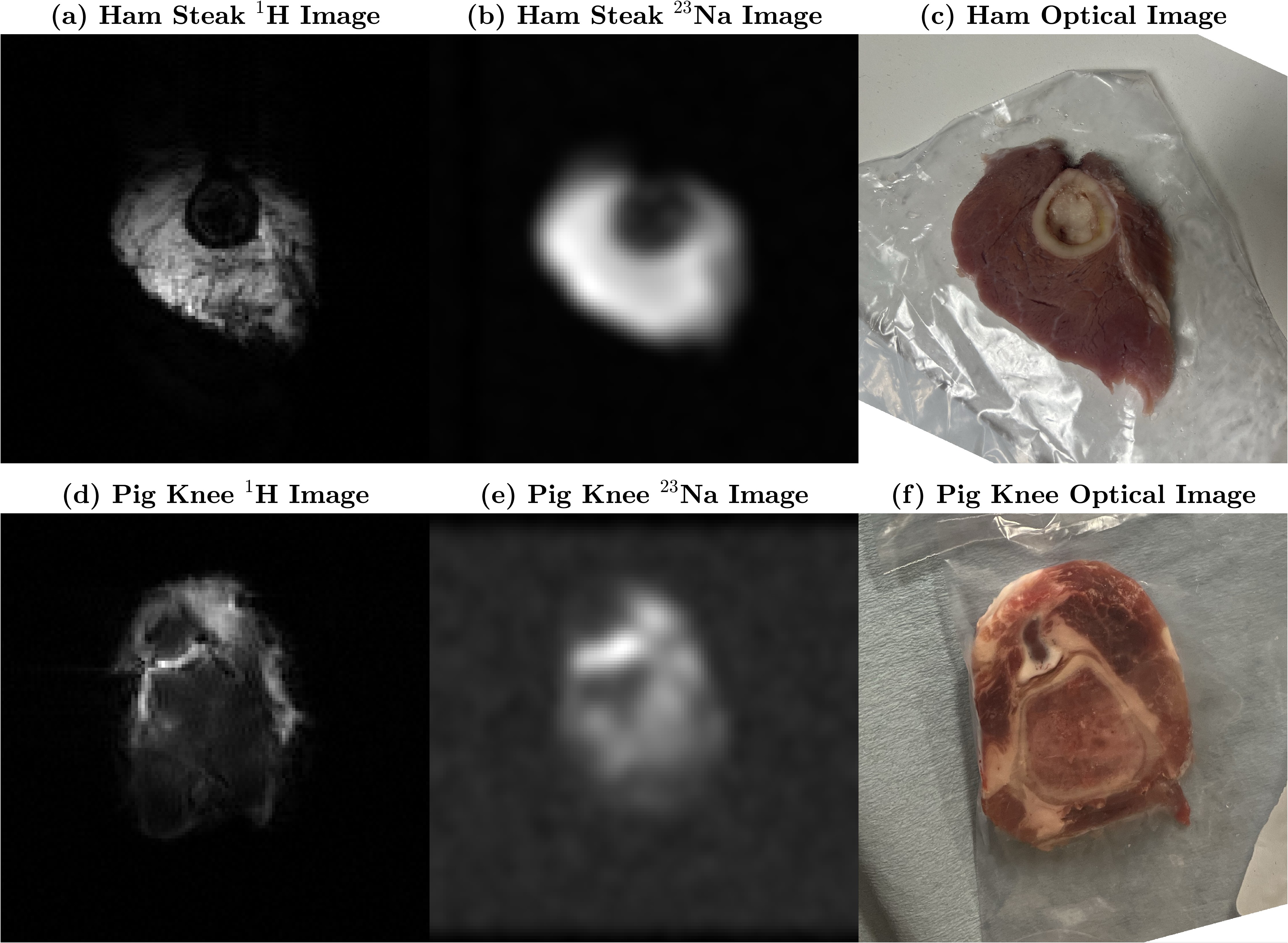
Figure 5 – 1H and 23Na Ex Vivo Magnetic Resonance Images Using the ADAPT Coil
1H and 23Na magnetic resonance images of a bone-in ham steak (a, b) and a pig knee (d, e) are shown. Optical images of the ham steak (c) and the pig knee (f) are also shown. The 1H images have low intensity due to field inhomogeneities in the small specimens.