Introduction: Parallel Transmit Concepts
Sydney Nicole Williams1
1University of Glasgow, United Kingdom
1University of Glasgow, United Kingdom
Synopsis
Keywords: Physics & Engineering: Pulse design, Physics & Engineering: Hardware, Physics & Engineering: RF Safety
This talk introduces parallel transmission (pTx) concepts that will be expanded upon in further speaker presentations during the session. The covered topics include a historical overview and motivation for pTx, multi-transmit radiofrequency (RF) coils, electromagnetic fields (EMFs) and specific absorption rate (SAR), mapping the transmit RF field, $$$B_{1}^{+}$$$, and static and dynamic pTx pulses.Outcome/Objectives
This educational talk on introducing parallel transmission (pTx) will cover the following topics that will later be expanded upon in follow-up speaker presentations:- Historical overview and motivation for pTx
- Multi-transmit radiofrequency (RF) coils
- Electromagnetic fields (EMFs) and specific absorption rate (SAR)
- Mapping the transmit RF field, $$$B_{1}^{+}$$$
- Static and dynamic pTx pulses
Historical overview and motivation for pTx
As the MRI community has explored higher and higher static field ($$$B_{0}$$$) strengths with higher Larmor frequency, the reduced RF wavelength begins to compare to regions of the body (e.g., wavelength roughly the size of the adult abdomen at 3T, or the adult head at 7T). This wavelength effect leads to constructive and destructive interference patterns of the transmit RF field ($$$B_{1}^{+}$$$) resulting in undesirable brightening and shading in images acquired at high and ultra-high fields (UHF). Parallel transmission was first proposed in the early 2000s as a mechanism for combatting $$$B_{1}^{+}$$$ field inhomogeneity associated with higher $$$B_{0}$$$ [1,2]. In an analog to the phased receive array [3], pTx is a hardware-based solution where an RF coil uses multiple transmit elements with independently generated $$$B_{1}^{+}$$$ fields to create a combined field pattern that can be optimized to improve RF homogeneity. Sticking to this analogy, pTx has furthermore been described as “Transmit SENSE” [4,5], whereby RF pulses can be accelerated by exploiting multiple transmit channels as is often done with parallel imaging [6,7,8]. With the recent introduction of medically-approved 7T MRI systems, advances in hardware and RF coil designs, and computing improvements for RF pulse design, pTx is no longer a niche, research-only branch of MRI but is quickly approaching wider adoption and eventual routine clinical use.Multi-transmit RF coils
Parallel transmission is achieved with a dedicated RF coil that has independently-driven transmit elements. In conventional MRI scanners, the scanner bore contains a transmit “body coil” birdcage resonator that uses quadrature excitation to generate the $$$B_{1}^{+}$$$ field [9] (Figure 1A [10]). Compared to pTx, the body coil excitation can be described as single transmission (sTx) since a single $$$B_{1}^{+}$$$ field is generated. One of the first steps towards implementing a pTx coil and system is shown in Figure 1B [11]. Here “RF phase shimming” is achieved by modifying the relative phase between elements of a multi-channel transmit coil whilst fixing the relative amplitude. In this instance, the same RF power amplifier (RFPA) is used to power each channel. Finally, a full pTx coil and system is shown in Figure 1C. In this case, each transmit channel is independently controlled, with its own RFPA that enables freely varying amplitude and phase. Modern commercial UHF MRI scanners now support full pTx with typically eight or sometimes sixteen transmit channels.In recent years, there have been significant advances into the design of pTx RF coils. Coils can broadly be classified by a few categorizations. First, coils can be either transceiver arrays (meaning transmission and reception happens with the same channel element), or they can be transmit (Tx)-only, receive (Rx)-only coils. In the latter case, a Tx-only, Rx-only coil generally has more Rx elements than Tx for improved signal-to-noise ratio (SNR) and parallel imaging capability. Secondly, pTx coils can be classified by the type of Tx element they use with microstrip transmission lines [10], loops [12], or dipoles [13] being the most common. Lastly, since nearly all pTx coils are local Tx coils, they can be categorized by the body region for which they are designed (e.g., head, spine, or chest array coils).
EMFs and SAR
As discussed above, the independent Tx elements of a pTx coil enables homogenization of the transmit RF field. Each Tx element generates its own electromagnetic field that superimposes to generate the combined $$$B_{1}^{+}$$$ field. This summation of multiple EMFs also has important implications for SAR deposition [5] and can lead to non intuitive local SAR “hotspots” [14]. Furthermore, the spatially varying local SAR is derived specifically from the electric fields, which are not measurable during a conventional MR imaging protocol. These spatially-varying EMFs and SAR properties of pTx have led researchers and users to develop thorough safety procedures and conservative SAR restrictions for scanning.Generally, all pTx safety tests involve EMF simulations of the pTx coil.The coil model can simulate the electric fields (and hence, SAR). If the simulation can be matched to experimental measurements, then it is typically assumed that the simulated model represents what happens in the scanner. The coil models are typically corroborated with experimental S-parameter and $$$B_{1}^{+}$$$ field map measurements, and through thermometry methods [15]. Once the model is validated, the EMF simulations can also be used to enable real-time local SAR prediction for any given pTx configuration. Virtual observation points (VOPs) [14,16], which compress large EMF simulations into clusters of SAR checkpoints, are a popular method for pTx SAR management and add an additional safety factor to pTx by overestimation. Recently the ISMRM Safety Working Group has created a full set of guidance on the best practices for testing and validation of pTx coils which includes a large amount of detail on EMF simulations and SAR [17].
Mapping the $$$B_{1}^{+}$$$ field
An important component to using pTx is $$$B_{1}^{+}$$$ field mapping. This is because each new subject placed within a pTx coil, and each new scan session, will load the coil in a unique way. Therefore, barring a few exceptions, the $$$B_{1}^{+}$$$ field should be measured or “mapped” at the beginning of every pTx session.Many methods for $$$B_{1}^{+}$$$ mapping have been proposed over the past few decades. Popular methods include actual flip angle imaging (AFI) [18], presaturated TurboFLASH [19], Bloch-Siegert shift [20], and DREAM [21], amongst others. More often than not, there is a trade-off between $$$B_{1}^{+}$$$ mapping accuracy and acquisition speed, particularly when mapping individual channels for pTx.
Static and dynamic pTx pulses
Finally, we introduce how pTx itself is actually performed. A simple form of parallel transmission is known as “static pTx” or $$$B_{1}^{+}$$$ shimming. Here, the relative amplitude and phase amongst Tx channels is modified to achieve a particular $$$B_{1}^{+}$$$ field pattern, yet the time-varying RF waveform itself stays the same [22]. $$$B_{1}^{+}$$$ shimming is easy to apply broadly to many imaging applications, yet is limited in its scope for $$$B_{1}^{+}$$$ field homogenization. “Dynamic” or “full” pTx is the more advanced form of pTx, where the amplitude and phase varies amongst each Tx channel, and also varies with time (i.e., the RF waveform for each channel is also distinct) [22]. Dynamic pTx also incorporates spatially varying excitation gradient fields whose excitation trajectories are selected to achieve their intended purpose (e.g., slice selection, non-selective excitation, or inner volume imaging). Dynamic pTx often requires advanced optimizations for specific applications, yet takes advantage of the full degrees of freedom afforded by parallel transmission.pTx optimization, whether it be $$$B_{1}^{+}$$$ shimming or full, dynamic pTx, can require expert users that are able to design the pTx shim or pulse to a measured $$$B_{1}^{+}$$$ map. In contrast to this tailored version of pTx, a recent concept known as “Universal Pulses” (UPs) has been introduced [23]. In the case of UPs, a set of pre-acquired $$$B_{1}^{+}$$$ (and $$$B_{0}$$$) maps are used to create a general pTx pulse that can then be applied to future scans for unseen subject $$$B_{1}^{+}$$$ and $$$B_{0}$$$ maps. Furthermore, the need for additional $$$B_{1}^{+}$$$ mapping is removed, which can improve scan time durations. While not as exact as tailored pTx, UPs offer an effective solution for lowering the burden involved and expertise required for using parallel transmission for some applications. In general, many more examples and applications for pTx shims and pulses exist, with many further RF pulse design solutions. These, and the general concepts introduced above, will be elaborated upon further throughout this educational session.
Acknowledgements
Thanks very much to colleagues from the University of Glasgow, NHS Greater Glasgow & Clyde, Siemens Healthineers UK, and Siemens Healthineers Germany, with whom I've had many lovely pTx conversations over the past few years.References
- Hoult DI, “Sensitivity and power deposition in a high-field imaging experiment.” Journal of Magnetic Resonance Imaging 12 pp46–67, 2000.
- Ibrahim TS, Lee R, Baertlein BA, Kangarlu A, and Robitaille P-ML, “Application of finite difference time domain method for the design of birdcage RF head coils using multi-port excitations.” Magnetic Resonance Imaging 18 733–42, 2000.
- Roemer PB, Edelstein WA, Hayes CE, Souza S P and Mueller OM, “The NMR phased array,” Magnetic Resonance in Medicine 16 192–225, 1990.
- Katscher U, Börnert P, Leussler C, and van den Brink J S, “Transmit SENSE.” Magnetic Resonance in Medicine 49 144–50, 2003.
- Zhu Y, “Parallel excitation with an array of transmit coils.” Magnetic Resonance in Medicine 51 775–84, 2004.
- Sodickson DK and Manning WJ, “Simultaneous acquisition of spatial harmonics (SMASH): fast imaging with radiofrequency coil arrays”, Magnetic Resonance in Medicine 38 591–603, 1997.
- Pruessmann KP, Weiger M, Scheidegger MB, and Boesiger P “SENSE: sensitivity encoding for fast MRI,” Magnetic Resonance in Medicine 42 952–62, 1999.
- Griswold MA, Jakob PM, Heidemann RM, Nittka M, Jellus V, Wang J, Kiefer B and Haase A, “Generalized autocalibrating partially parallel acquisitions (GRAPPA).” Magnetic Resonance in Medicine 47 1202–10, 2002.
- Glover GH, Hayes CE, Pelc NJ, Edelstein WA, Mueller OM, Hart HR, Hardy CJ,O’Donnell M and Barber WD, “Comparison of linear and circular polarization for magnetic resonance imaging.” Journal of Magnetic Resonance 64 255–70, 1985.
- Adriany G, Van de Moortele P-F, Wiesinger F, Moeller S, Strupp JP, Snyder C, Zhang X, Chen W, Pruessman KP, Boesinger P, Vaughan T, Uğurbil Ket al., “Transmit and receive transmission line arrays for 7 Tesla parallel imaging.” Magnetic Resonance in Medicine 53 434–45, 2005.
- Williams S, McElhinney P, and Gunamony S, “Ultra-high field MRI: parallel-transmit arrays and RF pulse design.” Physics in Medicine & Biology, 68 2023.
- Setsompop K, Wald LL, Alagappan V, Gagoski B, Hebrank F, Fontius U, Schmitt F and Adalsteinsson E, “Parallel RF transmission with eight channels at 3 Tesla.” Magnetic Resonance in Medicine 56 1163–71, 2006.
- Raaijmakers AJE, Ipek O, Klomp DWJ, Possanzini C, Harvey P, Lagendijk JJW and van den Berg CAT, “Design of a radiative surface coil array element at 7 T: the single-side adapted dipole antenna.” Magnetic Resonance in Medicine 66 1488–97, 2011.
- Lee J, Gebhardt M, Wald LL and Adalsteinsson E, “Local SAR in parallel transmission pulse design.” Magnetic Resonance in Medicine 67 1566–78, 2012.
- Hoffmann J, Shajan G, Scheffler K and Pohmann R, “Numerical and experimental evaluation of RF shimming in the human brain at 9.4 T using a dual-row transmit array.” Magnetic Resonance Materials in Physics, Biology and Medicine 27 373–86, 2014.
- Eichfelder G and Gebhardt M, “Local specific absorption rate control for parallel transmission by virtual observation points.” Magnetic Resonance in Medicine 66 1468–76, 2011.
- De Zanche N et al., “ISMRM best practices for safety testing of experimental RF hardware.” International Society for Magnetic Resonance in Medicine 1–119 https://www.ismrm.org/safety/RF_Hardware_Safety_Testing_2022-03.pdf, 2022.
- Yarnykh, VL, “Actual flip-angle Iiing in the pulsed steady state: a method for rapid three-dimensional mapping of the transmitted radiofrequency field.” Magnetic Resonance in Medicine 57 192-200, 2007.
- Sacolick LI, Wiesinger F, Hancu I, and Vogel MW, “$$$B_{1}$$$ mapping by Bloch-Siegert shift.” Magnetic Resonance in Medicine 63 1315-1322, 2010.
- Chung S, Kim D, Breton E, and Axel L, “Rapid $$$B_{1}^{+}$$$ mapping using a preconditioning RF pulse with TurboFLASH readout.” Magnetic Resonance in Medicine 64 439-446, 2010.
- Nehrke K, and Börnert P, “DREAM–A novel approach for robust, ultrafast, multislice $$$B_{1}$$$ mapping.” Magnetic Resonance in Medicine 68 1517-1526, 2012.
- Padormo F, Beqiri A, Hajnal JV and Malik SJ, “Parallel transmission for ultrahigh-field imaging.” NMR in Biomedicine 29 1145–61, 2016.
- Gras V, Vignaud A, Amadon A, Le Bihan D and Boulant N, “Universal Pulses: a new concept for calibration-free parallel transmission.” Magnetic Resonance in Medicine 77 635–43, 2017.
Figures
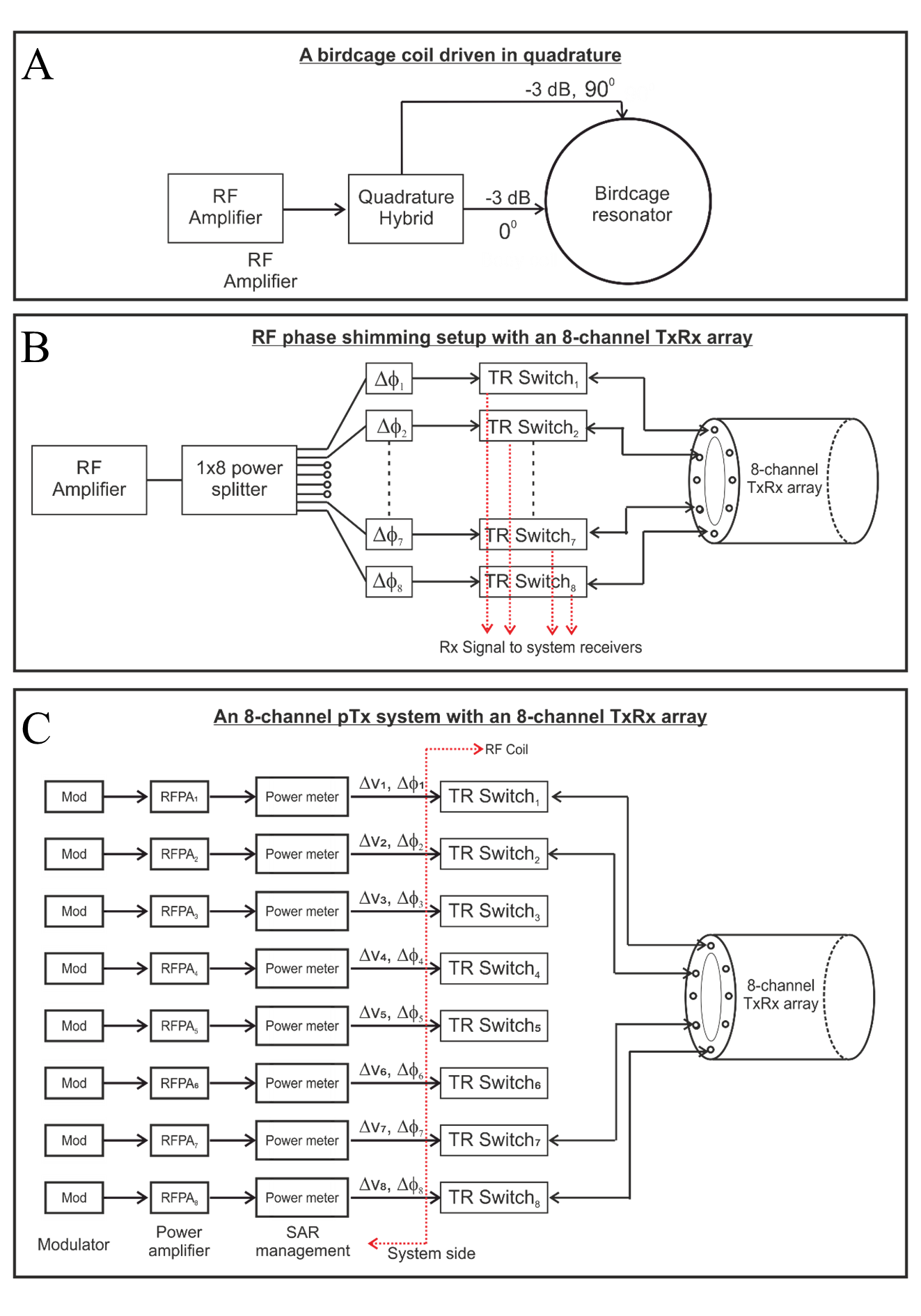
Figure 1. (A) Functional block diagram of a circularly polarized birdcage resonator. (B) A passive RF shimming setup consisting of a power splitter and an 8-channel TxRx array. The length of the coaxial cable between the power splitter and the coil input can be altered in this setup. (C) A dynamic pTx system which allows independent control of the amplitude and phase of the currents to the coil elements. Reproduced from Williams, McElhinney, and Gunamony, 2023 (Reference 11)