5281
An 8-channel Transmit Array for Prostate MRI at 7T Using Six Loops and Two Dipoles: A Simulation Study.1Imaging Centre of Excellence, University of Glasgow, Glasgow, United Kingdom, 2MR CoilTech Limited, Glasgow, United Kingdom
Synopsis
Keywords: RF Arrays & Systems, Prostate
Prospective 8 channel (6Tx loop + 2Tx dipole) body array intended for prostate MRI at 7T was simulated and its B1+ and SAR performance evaluated. The study demonstrated the capability of loop-based arrays to offer competitive levels of prostate imaging performance compared to current state-of-the-art hybrid and dipole arrays reported in the literature.Introduction
Use of dipole-based RF body arrays for UHF prostate MRI is well-established1,2, as they produce high B1+ field at tissue depth of above 5 cm whilst maintaining a comparatively low SAR that does not scale with the number of elements in a sparsely-spaced array, making SAR of individual elements a limiting factor for the overall SAR performance. However, the use of dipoles in an array comes with a disadvantage of a strong inter-element coupling and high sensitivity to sample loading. Whilst numerous solutions have been proposed to address these challenges, they come with trade-offs: placing resonant structures in between the dipoles to reduce the coupling distorts the B1 field3-5, and I-MARS array2, whilst showing excellent loading stability and decoupling figures, has comparatively poor B1+ efficiency.In contrast, loop elements are easily decoupled (either by overlapping or using a transformer), maintain acceptable B1+ at depth6 and demonstrate good tuning stability across different sample loads. Individually, loops can offer a significantly better SAR performance than dipoles, but unlike dipole arrays, loop array SAR performance degrades when more elements are introduced. The primary cause of SAR performance degradation is the loop proximity in a tightly-packed array, with SAR hotspots typically observed at the interface with neighbouring loops. The purpose of this simulation study was to demonstrate that loop-based body arrays have a potential to offer competitive SAR performance to state-of-the-art dipole and hybrid arrays reported in the literature in the context of prostate imaging1,2,7,8. The preliminary design presented in this abstract constitutes a shielded loop array comprising anterior and posterior rigid parts housing 3 overlapped loops each (6 in total) and further augmented by 2 lateral dipoles to bring the number of transmit channels up to 8 and improve lateral coverage.
Methods
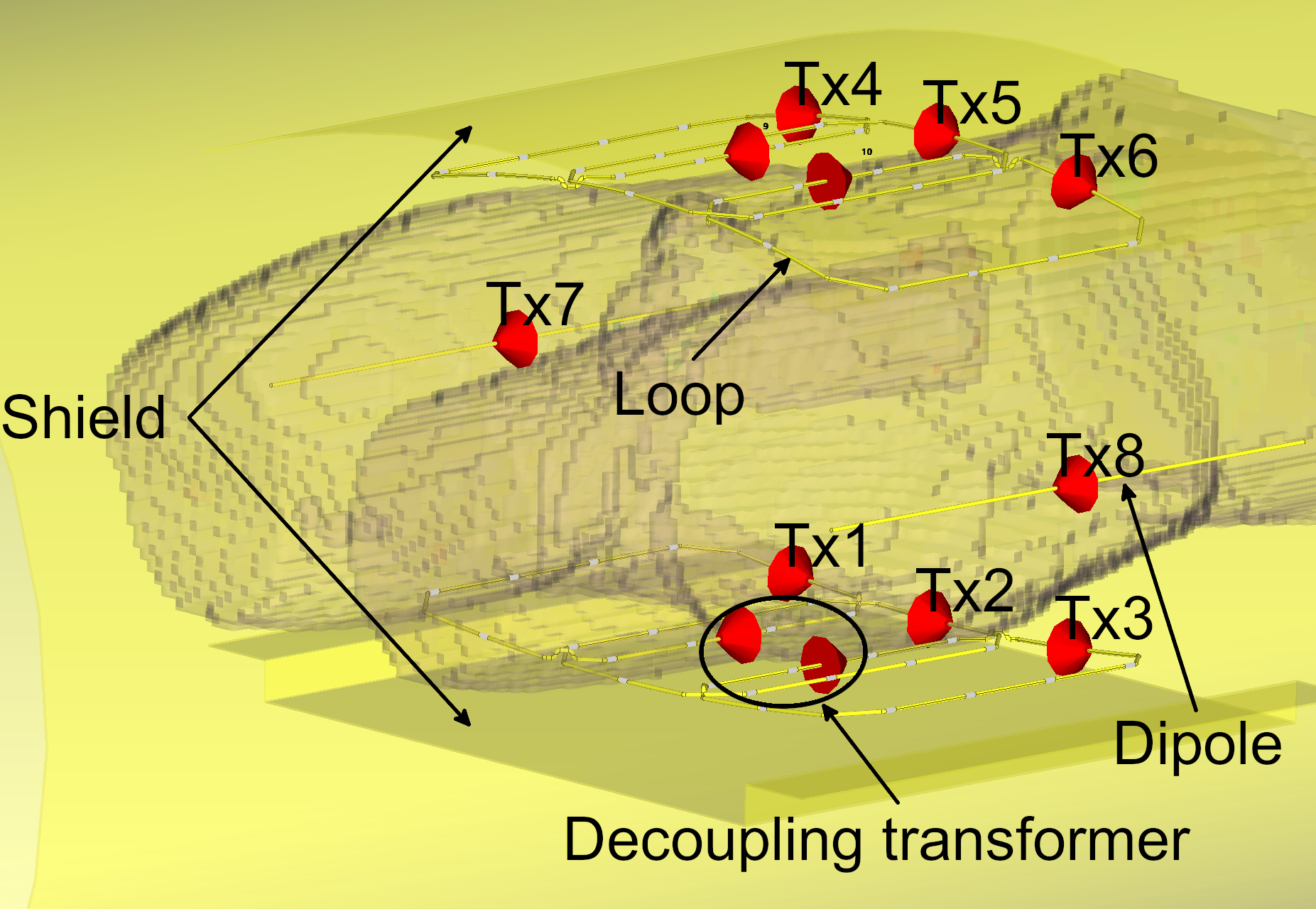
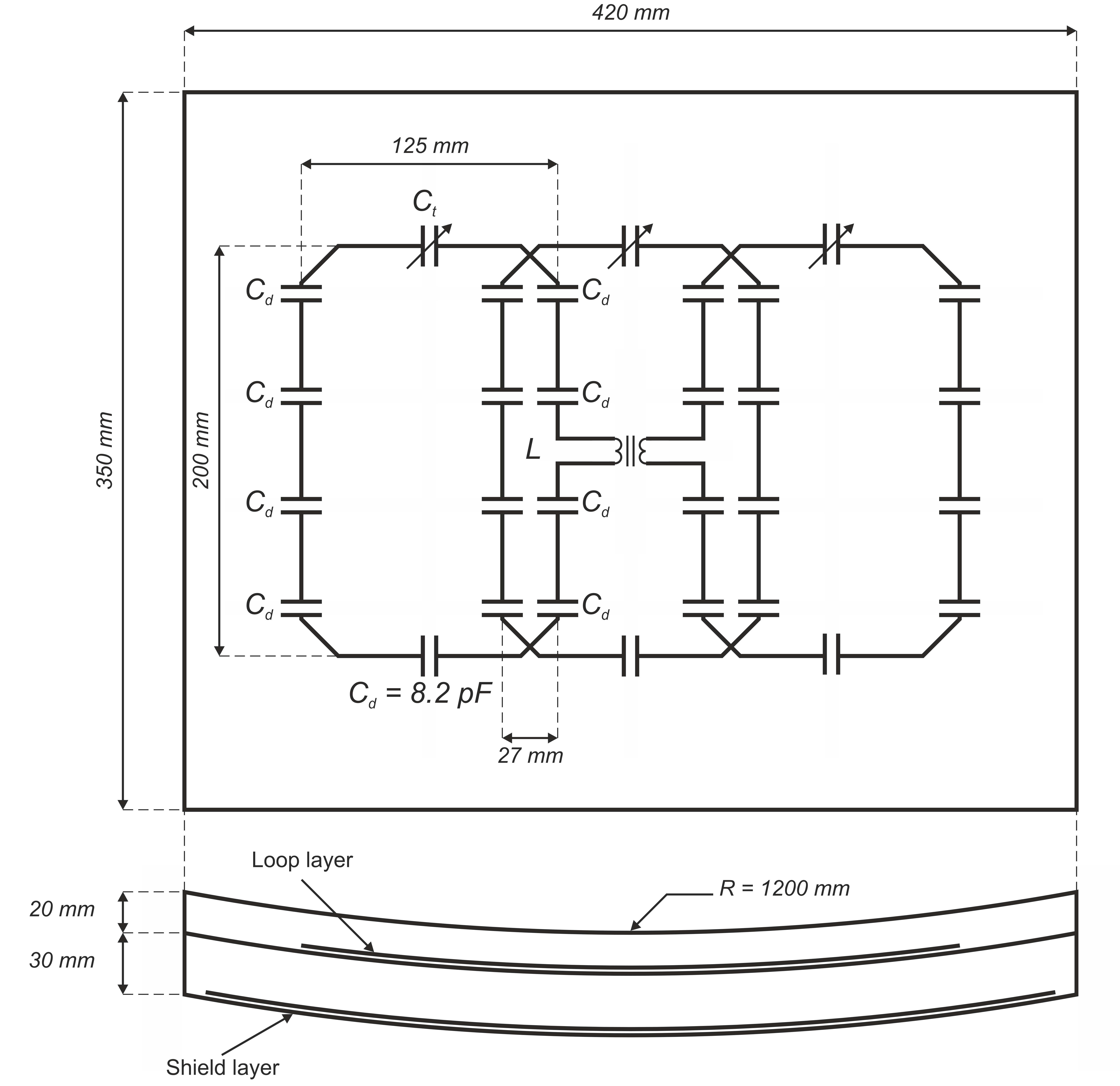
A finite-difference time-domain (FDTD) EM simulation of the prospective 6Tx loop + 2Tx dipole prostate array was performed in CST 2021 SP5 (CST Studio Suite, Dassault Systems, France) with 5 mm resolution Duke digital body model. Circuit co-simulation was used for matching and adjusting inductance of the solenoids used for the next-neighbouring loop decoupling. Full simulation setup and detailed array configuration are shown in Fig. 1 and Fig. 2, respectively. B1+ maps were exported for phase shimming in MATLAB. Each channel's shimming phase $$$\Phi_n$$$ was computed by averaging individual channel's phase9 within the 4x4x4 cm3 ROI centred around the prostate as per equation below, where $$$\phi_{n,m}$$$ is channel $$$n$$$ phase within the ROI voxel $$$m$$$. Per-channel amplitude adjustments were carried out manually to further reduce the SAR when it was observed that the major tissue hotspots were at the overlap of Tx1 and Tx2, and Tx3 and Tx4. B1+ and SAR performance were evaluated based on mean B1+ value within the prostate. Two sets of excitation vectors were considered: with and without the use of lateral dipoles.$${\Phi}_n = \sum_{m}e^{-i{\phi}_{n,m}}$$
Results and Discussion
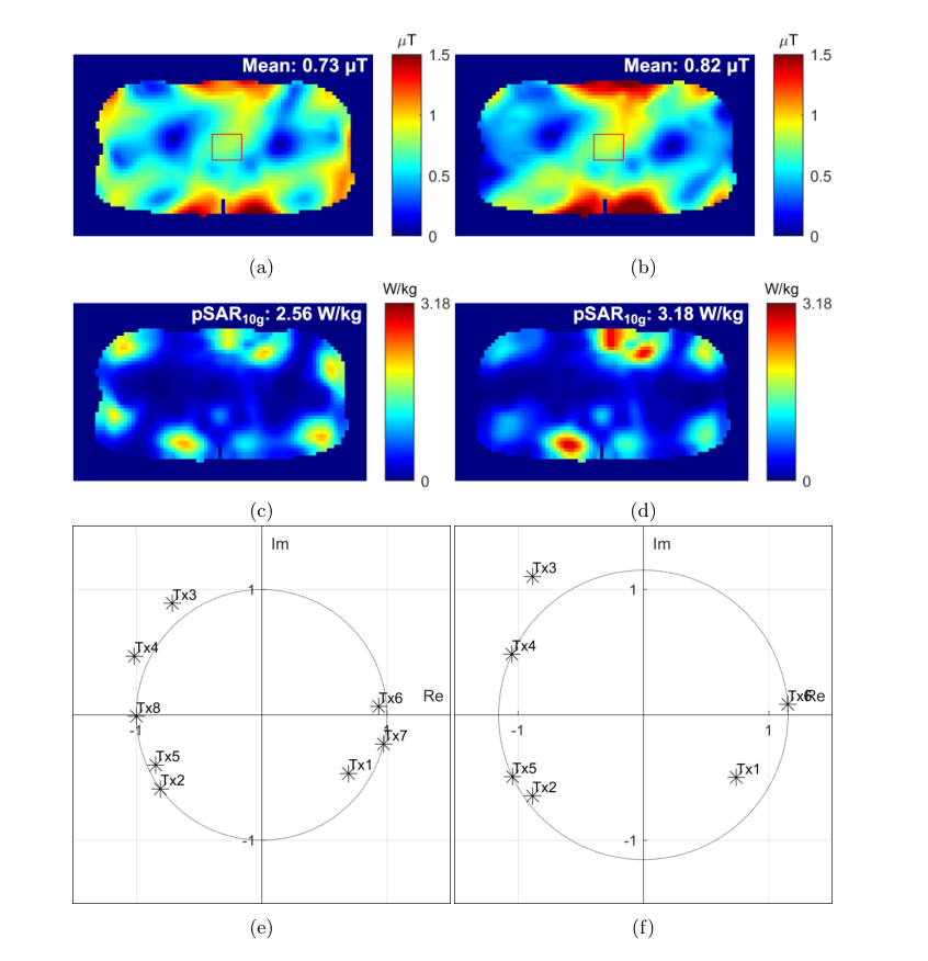
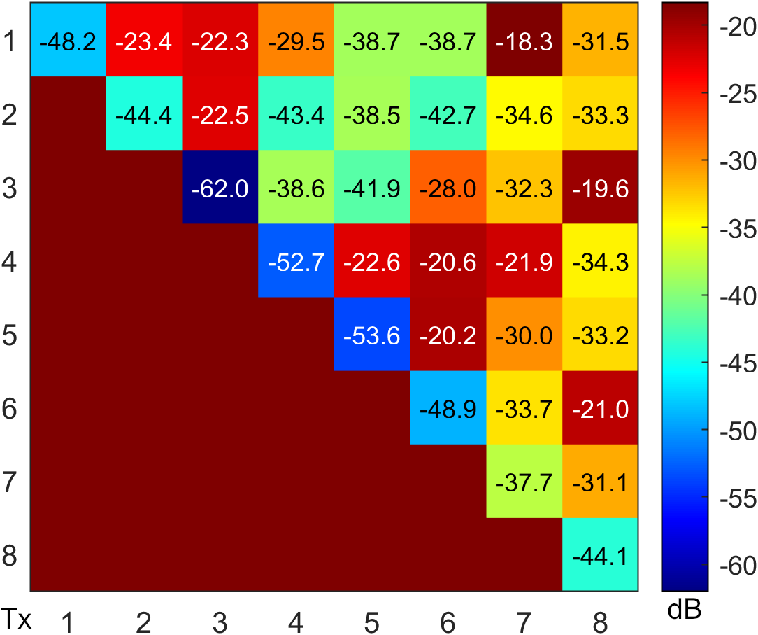
Simulated B1+ and SAR maps along with sets of shimming weights of the prospective array when driven with and without the dipoles are shown Fig. 3. When all 8 elements are driven, array demonstrates B1+ efficiency of 8.16 $$${\mu}T/\sqrt{kW}$$$ and SAR performance of 0.45 $$${\mu}T/\sqrt{W/\textit{kg}}$$$. When only loop elements are excited, B1+ efficiency within the prostate goes up to 9.2 $$${\mu}T/\sqrt{kW}$$$ (an improvement of 12.7%) with no loss in SAR performance, but at the cost of some lateral coverage. Scattering parameter matrix is presented in Fig. 4. Decoupling is better than than -18.3 dB for all elements, and better than -20.2 dB when only loops are considered. The strongest coupling is observed between the lateral dipoles and outer loops.SAR performance of the array is primarily hampered by the proximity of the loops to each other, leading to a formation of the hotspots at their overlap. Therefore, prostate imaging performance can potentially be improved by increasing the array element spacing. This would require a simultaneous loop width reduction if B1+ efficiency is to be maintained, since placing the array elements outwith the patient's posterior and anterior planes wastes power due to a large volume of tissue shielding the prostate laterally, as was indirectly shown by lateral dipoles having no effect on prostate excitation.
Conclusion
A prospective prostate array comprising anterior and posterior shielded parts housing 3 overlapped loops each and further augmented by 2 lateral dipoles was simulated and its B1+ efficiency, SAR performance, coupling and loading stability were assessed using Duke digital body model. Simulation results of the prototype array show a potential to offer an SAR performance of 0.45 $$${\mu}T/\sqrt{W/\textit{kg}}$$$, which is competitive with the current state-of-the-art arrays reported in the literature, whilst at the same time maintaining high B1+ efficiency of 8.16 $$${\mu}T/\sqrt{kW}$$$ and offering loading stability inherent to the loops, which demonstrates the feasibility of using loop arrays for 7T abdominal imaging.A major limiting factor for the SAR performance of the proposed array is neighbouring loop proximity, which leads to a formation of hotspots at the pair's interface. Future work involves constructing the coil and validating the simulation results, as well as examining the effects of loop geometry (width-to-length ratio) and spacing on the array performance when imaging the prostate.
Acknowledgements
No acknowledgement found.References
1. Raaijmakers AJ, Italiaander M, Voogt IJ, Luijten PR, Hoogduin JM, Klomp DW, van den Berg CA. The fractionated dipole antenna: A new antenna for body imaging at 7 Tesla. Magn Reson Med. 2016 Mar;75(3):1366-74
2. A. Destruel et al., "Integrated Multi-Modal Antenna With Coupled Radiating Structures (I-MARS) for 7T pTx Body MRI," in IEEE Transactions on Medical Imaging, vol. 41, no. 1, pp. 39-51, Jan. 2022
3. A. Hurshkainen et al., "Decoupling of Closely Spaced Dipole Antennas for Ultrahigh Field MRI With Metasurfaces," in IEEE Transactions on Antennas and Propagation, vol. 69, no. 2, pp. 1094-1106, Feb. 2021
4. Sharifian Mazraeh Mollaei, M.,Hurshkainen, A., Kurdjumov, S.,Glybovski, S., & Simovski, C. (2018).Decoupling of two closely locateddipole antennas by a split-loopresonator.Radio Science,53, 1398–1405
5. M. S.M. Mollaei, A. Hurshkainen, S. Kurdjumov, S. Glybovski, C. Simovski, Passive electromagnetic decoupling in an active metasurface of dipoles, Photonics and Nanostructures - Fundamentals and Applications, Volume 32, 2018, Pages 53-61
6. Raaijmakers AJ, Luijten PR, van den Berg CA. Dipole antennas for ultrahigh-field body imaging: a comparison with loop coils. NMR Biomed. 2016 Sep;29(9):1122-30
7. Ertürk MA, Raaijmakers AJ, Adriany G, Uğurbil K, Metzger GJ. A 16-channel combined loop-dipole transceiver array for 7 Tesla body MRI. Magn Reson Med. 2017 Feb;77(2):884-894
8. Paška J, Cloos MA, Wiggins GC. A rigid, stand-off hybrid dipole, and birdcage coil array for 7 T body imaging. Magn Reson Med. 2018 Aug;80(2):822-832
9. Metzger GJ, Snyder C, Akgun C, Vaughan T, Ugurbil K, Van de Moortele PF. Local B1+ shimming for prostate imaging with transceiver arrays at 7T based on subject-dependent transmit phase measurements. Magn Reson Med. 2008 Feb;59(2):396-409
Figures