5280
Geometrical Decoupling using Clip-path Conductor for 7T Transceiver Coil Array1Department of Health Sciences and Technology, GAIHST, Gachon University, Incheon, Korea, Republic of, 2Neuroscience Research Institute, Gachon University, Incheon, Korea, Republic of, 3Department of Biomedical Engineering, Gachon University, Incheon, Korea, Republic of, 4Brain Core Research Facility, Korea Brain Research Institute, Daegu, Korea, Republic of, 5Department of Neurology, Gill Medical Center, Gachon University College of Medicine, Incheon, Korea, Republic of
Synopsis
Keywords: RF Arrays & Systems, RF Arrays & Systems, Clip-path, Transceiver Array, Decoupling, MRI
We propose new geometrical decoupling method using clip-path conductor (CPC) to reduce the mutual coupling between individual elements in RF coil array. The 8-element CPC transceiver array was constructed based on electromagnetic (EM) simulation and applied to whole brain imaging at 7T.Introduction
An array coil with a high number of elements may offer parallel imaging (PI) with a high reduction (R)-factor and improve the RF efficiency and B1-shimming at UHF-field MRI1. In RF coil array design, several methods for decoupling based on geometrically (non-) overlapping2, transformers3, self-decoupling4, passive (capacitive and/or inductive) networks5, or pre-amplifier decoupling2 have been proposed to enhance magnetic flux decoupling in an array. In this study, we have proposed and evaluated a novel but simple and effective approach to decoupling loop coils using clip-path conductor (CPC) in RF coil arrays at 7T.Methods
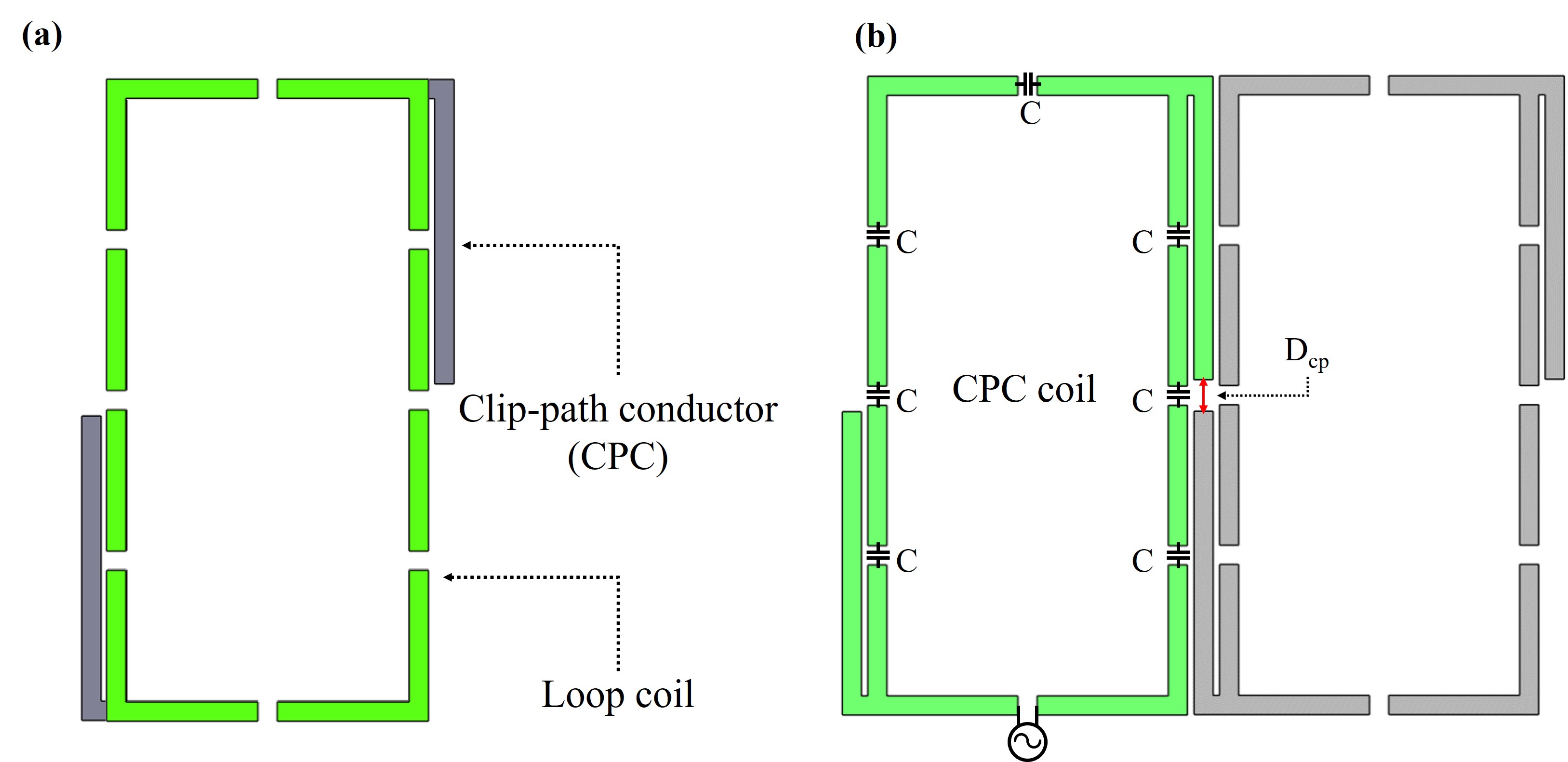
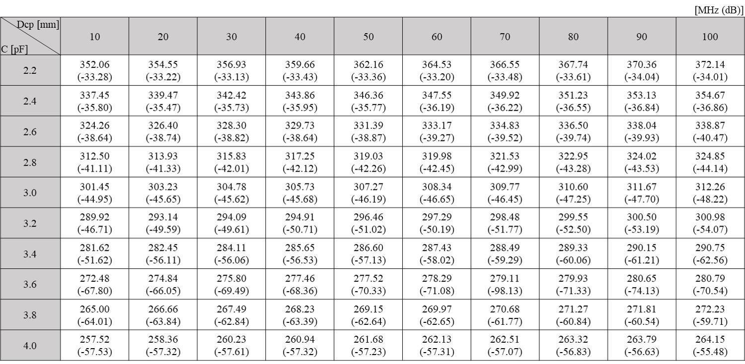
A transceiver array of 2-elements was modeled using EM simulation software (Sim4life by ZMT, www.zmt.swiss). Each coil element is in the form of a rectangular loop and has a width of 100mm, length of 200mm, and a conductor width of 6mm. The CPC consist of an extended conductor-line to the top right and bottom left of a conventional loop coil (gray line Fig. 1a). To exploring the decoupling performance, we tested with two coils with a separation of 10mm in this area the CPC was placed (Fig. 1b). In this CPC coil, decoupling performance can be controlled by adjusting the distance of clip-paths (Dcp in Fig. 1b) and the capacitance (C) in the loop coil. The transmission coefficients (Sji) of CPC coil array were measured according by changing Dcp and C. The range for Dcp was set from 10 to 100mm with 10mm intervals and the range of C was set from 2.2 to 4.0pF with 0.2pF intervals. EM simulations were performed for 2- and extended to 8-element RF coil array. The input power of each RF port was set to 1W of gaussian pulse at 300MHz of 7T. To verify the decoupling performance, the CPC coil array was compared with non-decoupled loop (NDL) coil in terms of scattering parameters and RF transmit (|B1+|)-field. Each RF coil array was built on a cylindrical former (diameter/length: 280/200mm). A cylindrical phantom (diameter/length: 210/180mm, composition: σ: 0.9732S/m, εr: 59.7194) was positioned in the iso-centre. The 8-element CPC coil array was manufactured, each element was tuned to 297.2MHz and matched at 50Ω and Sji and reflection coefficients (Sii) were measured. The MRI experiments were performed using a 7T scanner (Magnetom, Siemens AG, Berlin, Germany). We acquired gradient recalled echo (GRE) images (TA: 2:08s, TR/TE: 400/10ms, FA: 30°, FOV: 256×256mm2, Matrix size: 256×256mm2, Slice thickness: 1.5mm) of cylindrical phantom (diameter/length: 180/160mm, composition: 1000g H2O (distilled water); 1.25g NiSO4 + 6H2O and 5g NaCl) and healthy volunteer of 24 years old.Results
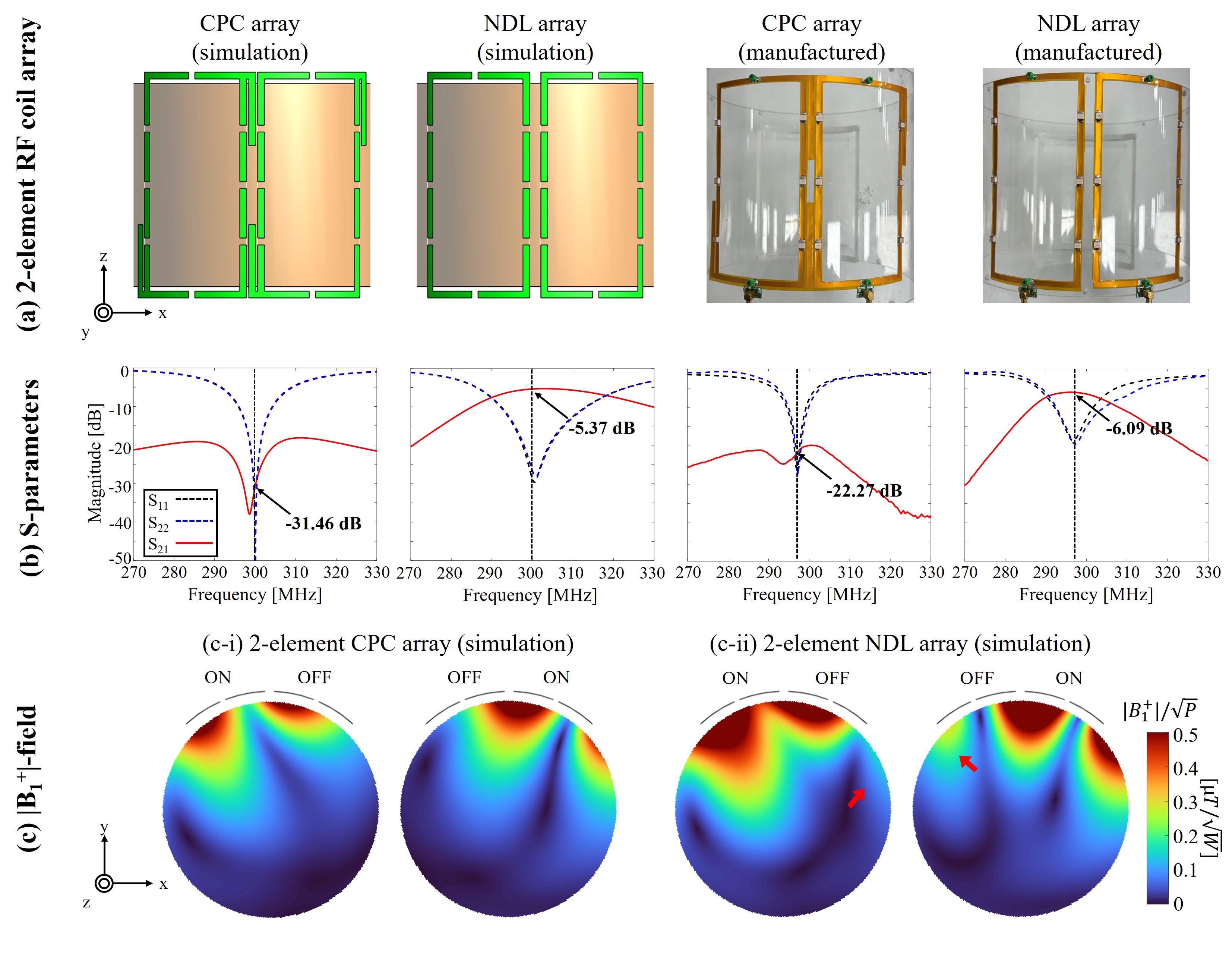
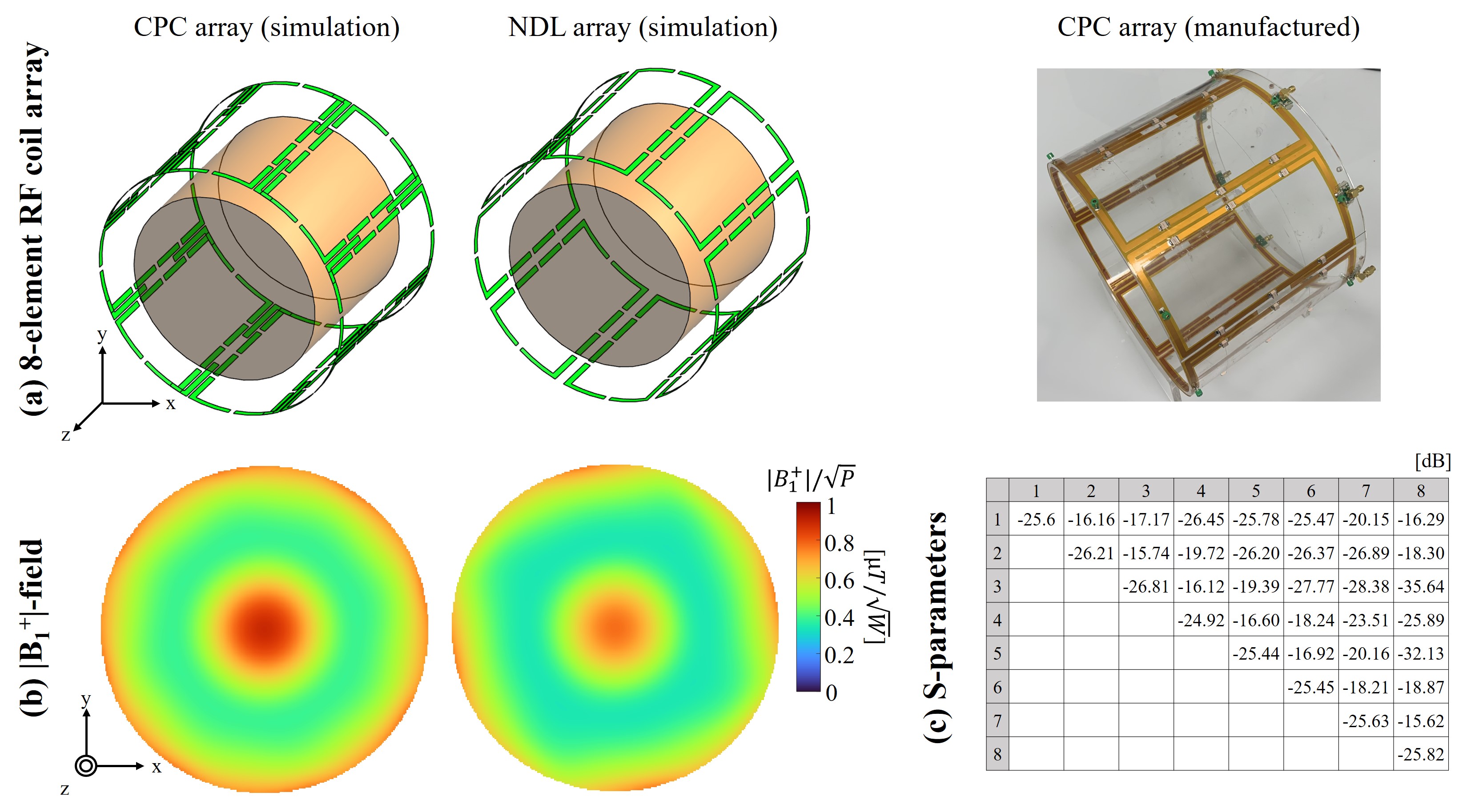
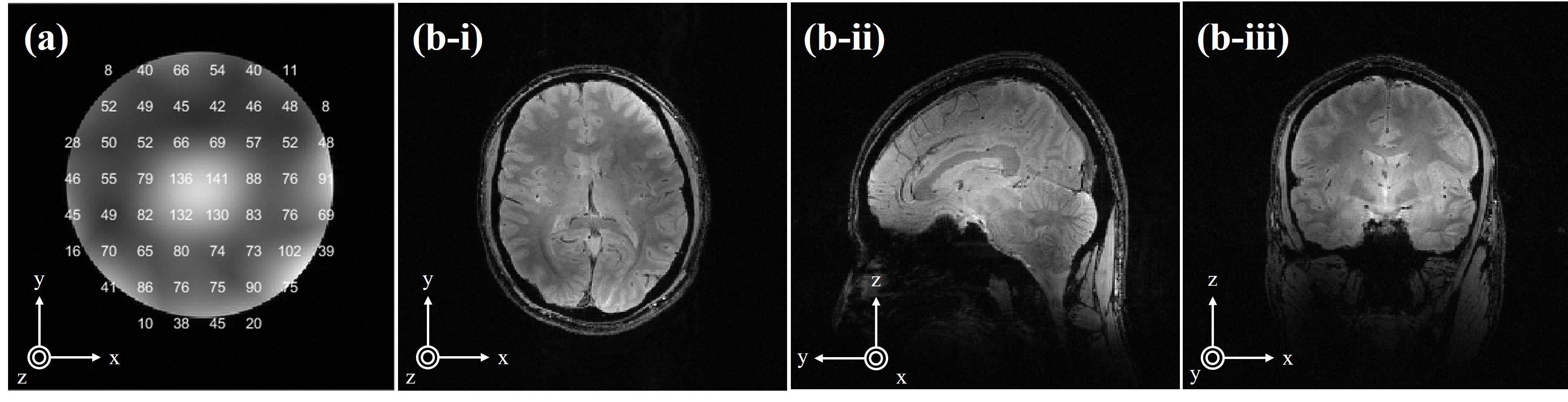
The decoupling performance of the CPC array proposed can be partially controlled by changing its values using Dcp and C. Fig. 2 shows the minimum Sji and the frequency according to Dcp and C. Superior decoupling performance was achieved when C and Dcp were 3.2 pF and Dcp to 70mm, respectively. The decoupling with this configuration had a -31.46dB of Sji while the reference NDL array was -5.37dB. In the bench measurement, the Sji of 2-element NDL and CPC array was -6.09 and -22.27dB, respectively. The geometry modeling (Fig. 3a), S-parameter (Fig. 3b), and |B1+|-fields (Fig. 3c) for each element for CPC array and NDL array are shown in Fig. 3. Non-operating NDL element generates an additional |B1+|-field due to strong coupling, which is indicated by the red arrows (Fig. 3c-ii). In case of 8-element CPC array (Fig. 4a), Sii and Sji was less than -50.24 and -22.53dB, however, NDL array shown less than -30.17 and -7.85dB in Sii and Sji, respectively. The |B1+|-fields of 8-element CPC and NDL array were compared in only 75% area of central axial-plane (Fig. 4b). The different mean of |B1+|-intensity was 0.47 and 0.41μT for CPC and NDL array. Therefore, the 8-element CPC array showed about 12.76% higher |B1+|-intensity than NDL coil array. However, the uniformity measured using a normalized absolute average deviation (NAAD)6 was 79.91 and 81.01% for CPC and NDL array, respectively. In the bench measurement, the Sji of all elements of 8-element CPC array was less than -15.62dB (Fig. 4c). From EM simulation and bench measurement clearly show that CPC geometry show minimized magnetic flux as compared to the NDL array. The SNR of the phantom was measured using NEMA MS 4-1 method7 (Fig. 5a) and the mean of SNR in the 75% of the whole phantom area was 73.89. In addition, the GRE images of healthy volunteer were acquired in axial, sagittal and coronal plane (Fig. 5b).Discussion and Conclusion
In this study, a new CPC decoupling method in RF coil array was proposed. The decoupling performance of CPC has been demonstrated through EM simulation and bench measurement, and 7T GRE images were obtained using 8-element CPC coil array. Although, S-parameter of the CPC coil could be changed predominantly with C, the decoupling performance can be achieved by changing the values of C and Dcp. In the future, we will use the proposed CPC array coil for PI capability and acquired MR images with high R-factor.Acknowledgements
This research was supported by KBRI basic research program through Korea Brain Research Institute funded by Ministry of Science and ICT (22-BR-05-02) and Institute for Information & communications Technology Promotion (IITP) grant funded by the Korea government (MSIP) (No. 2021-0-00490, Development of precision analysis and imaging technology for biological radio waves), and this research was approved by the Institutional Review Board/Ethics Committee (IRB no. GDIRB2016–347) of Gachon University Gil Medical Center. Written informed consent was obtained from all study participants included in the study.References
1. Payne K, Ying LL, Zhang X. Hairpin RF resonators for MR imaging transceiver arrays with high inter-channel isolation and B1 efficiency at ultrahigh field 7 T. Journal of Magnetic Resonance. 2022;345:107321.
2. Roemer PB, Edelstein WA, Hayes CE, Souza SP, Mueller OM. The NMR phased array. Magnetic Resonance in Medicine. 1990;16(2):192-225.
3. Kim JH, Moon CH, Park BW, Furlan A, Zhao T, Bae KT. Multichannel transceiver dual-tuned RF coil for proton/sodium MR imaging of knee cartilage at 3 T. Magnetic Resonance Imaging. 2012;30(4):562-571.
4. Yan X, Gore JC, Grissom WA. Self-decoupled radiofrequency coils for magnetic resonance imaging. Nature Communications. 2018;9(1).
5. Kim KN, Kim YB, Cho ZH. Improvement of a 4-Channel Spiral-Loop RF Coil Array for TMJ MR Imaging at 7T. Journal of the Korean Society of Magnetic Resonance in Medicine. 2012;16(2):103.
6. National Electrical Manufacturers Association. NEMA Standards Publication MS 3-2008: Determination of Image Uniformity in Diagnostic Magnetic Resonance images, 2008. Virginia, USA; 2008.
7. National Electrical Manufacturers Association. NEMA Standards Publication MS 1-2008: Determination of Signal-to-Noise Ration (SNR) in Diagnostic Magnetic Resonance Imaging, 2008. Virginia, USA; 2008
Figures