5279
Design and construction of a 14-channel receive-only array for high resolution MRI of marmosets’ brain at 9.4T
Daniel Papoti1,2, Diego Szczupak1, David Schaeffer1, and Afonso Silva1
1Department of Neurobiology, University of Pittsburgh, Pittsburgh, PA, United States, 2Center for Engineering, Modeling and Applied Social Sciences, Federal University of ABC, Sao Bernardo do Campos, Brazil
1Department of Neurobiology, University of Pittsburgh, Pittsburgh, PA, United States, 2Center for Engineering, Modeling and Applied Social Sciences, Federal University of ABC, Sao Bernardo do Campos, Brazil
Synopsis
Keywords: RF Arrays & Systems, RF Arrays & Systems, Receive Arrays
The present work describes the design characterization and tests of a 14-channel receive-only array for marmoset brain MRI at 9.4T. The coil was designed to maximize the SNR over the entire head of a common marmoset, considering the anesthesia apparatus, such as ear bars and anesthesia mask.Introduction
The common marmoset (Calithrix jacchus) is a new world primate of increasing interest to neuroscience and translational brain research, in which MRI and fMRI plays a fundamental role in providing both anatomical and functional data of the monkey’s brain. One promising application is the development of genetically engineered marmoset models of Alzheimer’s disease [1]. For such applications, the longitudinal evaluation of the brain anatomy during early postnatal development throughout lifespan using ultrahigh field MRI is essential to follow-up different stages of the disease progress, requiring whole brain images with high spatial resolution. In this work, we describe the development and characterization of a 14-channel receive-only array customized for whole brain MRI of anesthetized marmosets at 9.4T.Methods
A 14-channel receive-only array was built, characterized and tested in a 9.4T/30 cm USR magnet (Bruker Biospin Inc, Ettlingen, Germany). Figure 1A shows the layout of the receive elements. Each coil element was built using AWG-18 copper wire and with 20 mm inner diameter, except for the elements near the temporal lobe (coils # 8, 9, 13, and 14), which were built with 25 mm inner diameter. These elements were made bigger to provide deeper penetration with high sensitivity, since marmosets have a thick temporalis muscle. The support used for assembling the coil was designed in Solidworks (Dassault Système, Waltham, MA) and 3D printed in gray resin (formlabs, Somerville, MA). The support design for the coil included holes to allow clearance for ear bars that restrain head motion when the animal is anesthetized. In addition, the support design allowed for the use of a face mask to deliver inhalational anesthesia. All the nearest neighbor elements were partially overlapped to minimize mutual inductance. The coil circuitry for each individual element in the 16-Channel receive array consisted of a matching network and a PIN diode-controlled blocking circuit for active detuning [2]. To avoid common modes in the cables, cable traps were inserted after between the matching network and the preamplifiers. Decoupling between non nearest neighbors' coils was achieved by connecting the elements to low noise preamplifiers through a p-network phase shifter, combined with 50Ω coaxial cables (RG-196) adjusted to provide an equivalent λ/2 cable at the input of the preamplifiers (WMA9RA,WanTcom Inc., Chanhassen, MN). The preamplifiers were assembled in 4 PCBs, each with 4 channels, as shown in Figure 1B. All the loop elements, matching network and active detuning circuit were assembled in the 3D printed support as shown in Figure 1C. The coil was characterized on the workbench [3] using a Vector Network Analyzer (ZNL3, R&S, Columbia, MD) by evaluating the unloaded/loaded quality factor (Q) ratio, including the isolation provided by the active detuning circuit and the preamplifier decoupling. Individual SNR maps and noise correlation matrix were obtained in the scanner when the coil was loaded with a phantom filled with CuSO4 x 2H2O 1g/L. T2 weighted images with 250 µm isotropic resolution were acquired in a 9.4T/30 cm USR magnet (Bruker-Biospin, Inc, Ettlingen, Germany) connected to an AvNeo console running ParaVision 360. The sequence used was a T2 RARE with TE=48ms, TR=7209ms, RARE factor=7, matrix = 256 x 256, FOV = 40 x 40 mm, slice thickness = 0.5 mm and 5 averages, resulting in acquisition time of 21 min 37 s.Results
The workbench measurements of isolation provided by the PIN diode controlled active detuning circuit were, on average, 32 dB, and the isolation provided by the low input impedance preamplifiers was better than 15 dB for all the elements. The Q measurements of the coil unloaded was Qu=253 and QL=150 when the coil was loaded, resulting in a ratio Qu/ QL=1.68. Figure 2 shows the noise correlation matrix obtained from a noise-only acquisition. The average correlation coefficient was 2.89% for the non-diagonal elements, with the maximum correlation coefficient of 15.57% between channels 13 and 14, which indicate a residual coupling between these channels.The individual SNR maps obtained from coronal orientation of a phantom are shown in Figure 3. Although most elements seem to be well decoupled, channel-9 shows loss of sensitivity. The sum-of-square reconstructed image shows good coverage with high sensitivity throughout the entire volume of interest.
T2-weighted anatomical brain images of a marmoset were acquired and are shown in Fig. 4. The images have 156 µm in plane resolution, with 500 µm slice thickness.
Discussion
The Q measurements for the loaded and unloaded condition indicates that, for this element size and frequency of operation, the losses are mainly in the coil dominating regime. This means that using thicker wire gauge might improve the SNR. The SNR maps obtained show that the coil elements are well decoupled and retain high local sensitivity, as confirmed by the noise correlation matrix. However, element #9 presented lower SNR, and further investigation is necessary to determine whether the problem is in the resonant loop itself or in the preamplifier.Conclusion
We have built and tested a 14-channel receive-only array for MRI of the marmoset brain at 9.4T. The SNR maps indicate that the sensitivity of element-9 can be further improved, but overall, all the remaining elements are well decoupling with good sensitivity and coverage for the volume of interest.Acknowledgements
No acknowledgement found.References
[1] RIZZO, Stacey J. Sukoff et al. Establishing the marmoset as a non‐human primate model of Alzheimer’s disease. Alzheimer's & Dementia, v. 17, p. e049952, 2021.
[2] GRISWOLD, Mark A. Characterization of multichannel coil arrays on the benchtop. eMagRes, 2007.
[3] PAPOTI, Daniel et al. Optimization of an 8-channel receive-only surface array for whole brain MRI of marmosets. In: Proceedings of the 23rd Annual Meeting ISMRM. 2015. p. 3176.
Figures
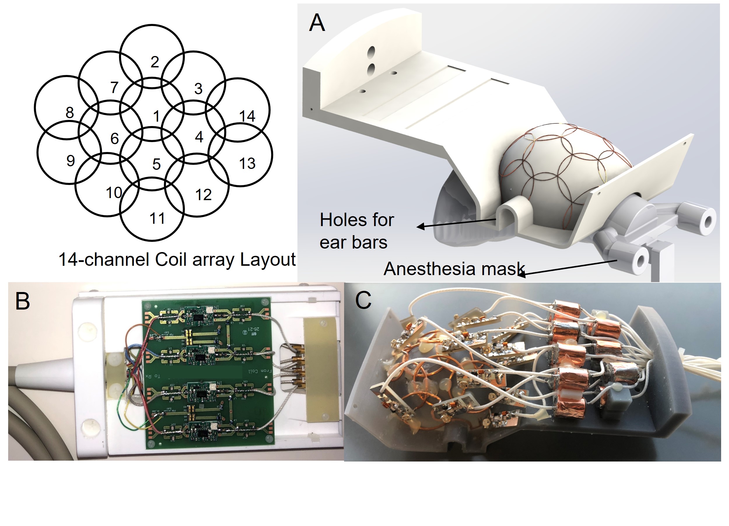
Figure-1: (A) 14-channel coil layout and rendered 3D file of the coil support showing elements in place. (B) PCB with 4 low noise preamplifiers assembled in a box with ODU non-magnetic connectors. (C) Picture of the 14-channel receive array showing all the loop elements, including the matching network PCBs and cable traps.
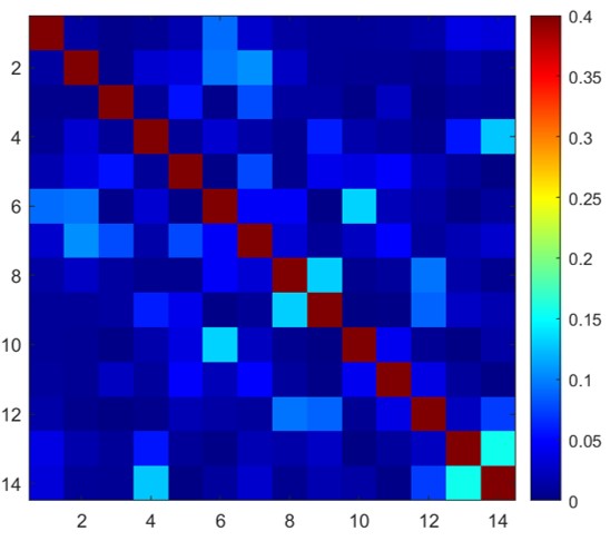
Figure 2: Noise correlation matrix measured for the 14-channel receive array. Maximum correlation coefficient was 15.6%, measured between channels 13 and 14. The average value of the non-diagonal coefficients was 2.89%.
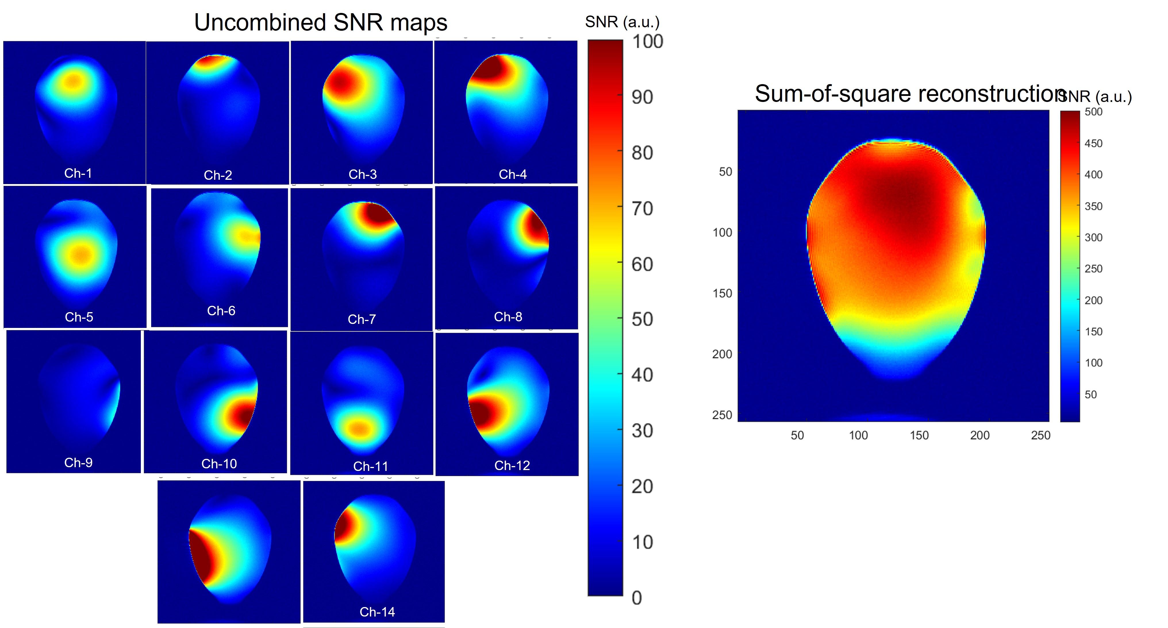
Figure 3: (Left) Individual SNR maps obtained from the phantom in the coronal orientation. (Right) Sum-of-square reconstruction of the individual images showed in the left.
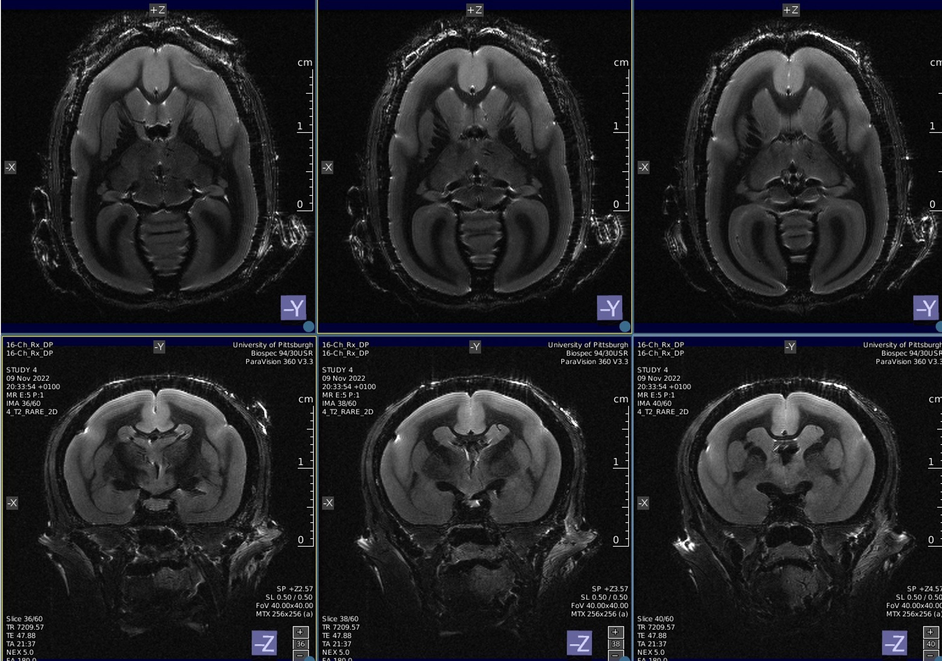
Figure-4: Axial and coronal T2 weighted images from a marmoset brain 14-channel receive array. The images have 156μm in plane resolution, with slice thickness of 500 μm.
DOI: https://doi.org/10.58530/2023/5279