5277
A Channelized Front-End for Single Port Multi-Tuned RF Coils
Courtney Bauer1, Jue Hou1, Chenhao Sun1, and Steven M. Wright1
1Department of Electrical and Computer Engineering, Texas A&M University, College Station, TX, United States
1Department of Electrical and Computer Engineering, Texas A&M University, College Station, TX, United States
Synopsis
Keywords: RF Arrays & Systems, RF Arrays & Systems
Increased interest in simultaneous and interleaved MR imaging and spectroscopy has led to the increased interest in multi-tuned coils and coil arrays. The introduction of single port, multinuclear coils resolves the complexity resulting from nested coils, but introduces new challenges in optimization of signal conditioning. Presented here is a channelization approach that enables frequency specific gain and filtering of signals from single port multinuclear coils.Introduction:
With the ever-increasing interest in performing simultaneous and interleaved MR imaging and spectroscopy, considerable effort has been dedicated to development of the multi-tuned coils to support these interests. These multi-tuned coils take many forms, some with different frequencies on separate ports, some with just a single port for all frequencies. No matter the configuration, two challenges can arise given either case: one, the frequencies could have significantly different signal amplitudes, and two, the employed receiver may need bandpass filtering around the frequency of interest. Both challenges can be addressed with the implementation of frequency specific gain and filtering in the RF front end1 but this can prove difficult with a single-port setup, as both frequencies are on the same cable. Even in the absence of filtering, gain optimization for the low amplitude frequency is likely to result in receiver saturation for the high amplitude frequency, while conversely optimizing for the high amplitude frequency is likely to result in inefficient utilization of the receiver’s dynamic range for the low amplitude frequency. In this abstract we demonstrate a channelized filter/gain front end system that can be easily implemented for a single cable, multi-tuned receiver coil.Methods:
The target application for this channelization is use with arrays of single-port, multinuclear coils. The first stage of amplification comes at the coil, with a high impedance preamplifier used for broadband decoupling2 with a second stage of amplification following immediately after. This is the original receive path employed prior to channelization, underscored in blue in Figure 1. At the end of these two stages, the signal has been boosted by approximately 51dB of gain, and at such point the channelization hardware can be introduced without significant impact to the SNR. The channelization path introduced is presented in Figure 1, underscored in red. The signal is fed into a splitter, then follows a path targeted for a specific nuclei’s frequency. Traditionally, attenuation would follow after amplification, but here we introduce it before as a means to avoid saturation of the channel specific amplifiers, but the primary purpose of the attenuators are to control the signal amplitude. The introduction of the high gain LNA at the last stage is intentional, as it prevents early saturation of the later stage amplifiers. Once boosted to the target amplitude, the signal is filtered at the desired frequency and recombined. The noise from the alternate channel is suppressed by the filter, so combining does not have an adverse effect on SNR. To test the performance of the channelization hardware, profiles were obtained with the goal of equalizing the signal amplitudes at the receiver. This data was acquired using an identical gradient echo pulse sequences, at 30.72 MHz and at 52.94MHz, which are the resonant frequencies of deuterium and sodium at 4.7T, respectively. Profiles were collected with and without the channelization hardware, in each instance 64 averages were collected.Results and Discussion:
Figure 2 shows the reconstruction of the data. As can be seen, prior to the implementation of the channelization hardware, the signal amplitudes between the original 2H and 23Na datasets (A and B) are quite different, with the spectrum peak of 23Na being 16.5% that of the 2H peak. The channelized attenuators were set to compensate this peak, with signals observed essentially the same, to the 1 dB resolution of the variable attenuator, as can be seen in the channelized data (C and D). Most importantly, the SNR of the individual channels was essentially unchanged, with 2H seeing a 3.11% increase while 23Na saw a 4.3% decrease. Normalized plots are included in Figure 2 as well, in plots E-H. Note that the peaks in the 2H data are a higher concentration region within the phantom. Noise figure and gain measurements for the overall system and individual components are included in Figure 3. Figure 3 shows the channelization path for a single channel, with approximately 12.47dB of attenuation at 30MHz, and 13.97dB of attenuation at 50MHz. The additional attenuation introduced accounted for these values such that the loss in the path was recovered with the channelized LNA, as can be seen in the overall gain of the system. The overall NF agrees well with the noise figure calculations made using the measurement of individual components, as can be seen in the final two columns of Figure 3.Conclusion:
This work demonstrates the potential application for channelized front-ends, commonly used in other communications areas3,4 to optimize gain and filtering when using single port multi-tuned coils. The objective of this abstract was to introduce independent gain and filtering for the target nuclei, without detriment to SNR, and was successful as the SNR fluctuation were within 5% that of the original reference. Future work includes further optimization of the system, including selection of amplifiers and redistribution of attenuation, as well as investigating the performance at larger signal discrepancies.Acknowledgements
This research was funded by the NIH grant RO1EB028533.References
1. C. H. Huang, S. E. Ogier, M. Gu, and S. M. Wright, "Flexible RF Filtering Front-End For Simultaneous Multinuclear MR Spectroscopy," Conf Proc IEEE Eng Med Biol Soc, vol. 2018, pp. 1368-1371, Jul 2018, doi: 10.1109/embc.2018.8512558.
2. Sun et. al. Proc ISMRM 2023, 3374; (submitted)
3. V. K. Singh and R. Gharpurey, “Channelized front-ends for broadband signal processing with sub-band dynamic range control”, 2018.
4. J. Kim, D. R. Utomo, A. Dissanayake, S.-K. Han, and S.-G. Lee, “The Evolution of Channelization Receiver Architecture: Principles and Design Challenges”, IEEE Access, vol. 5, pp. 25385–25395, 2017.
Figures
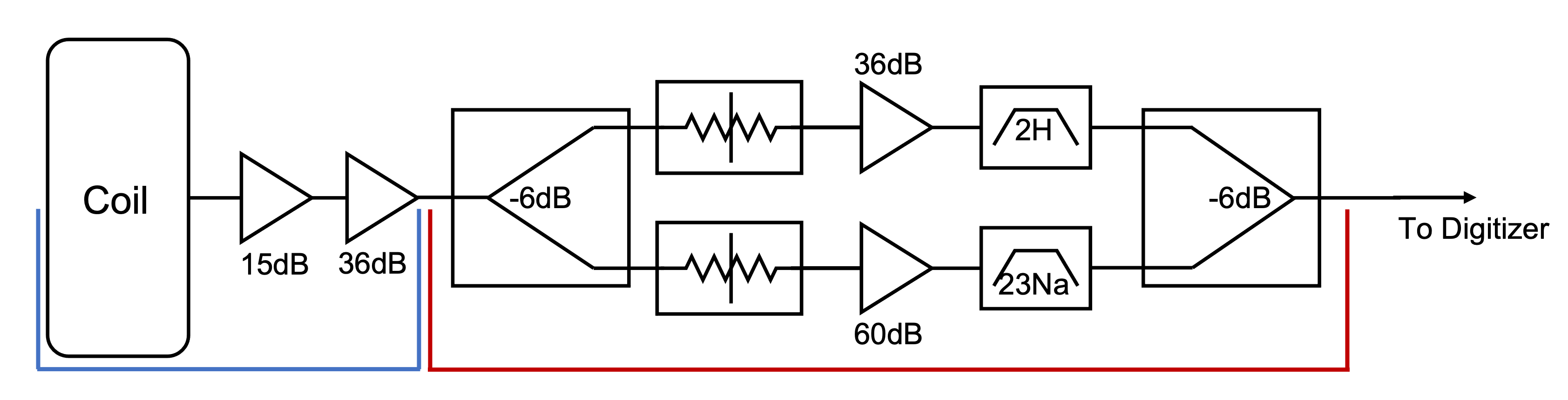
Figure 1: Block diagram illustrating the original receive path (blue) and the additional hardware introduced with the channelization setup (red) intended for use with a single array element. The variable attenuators are placed before the channelized amplifiers to avoid accidental saturation of the LNA. The low noise figure in the early amplifiers dominates the noise figure to make this possible.
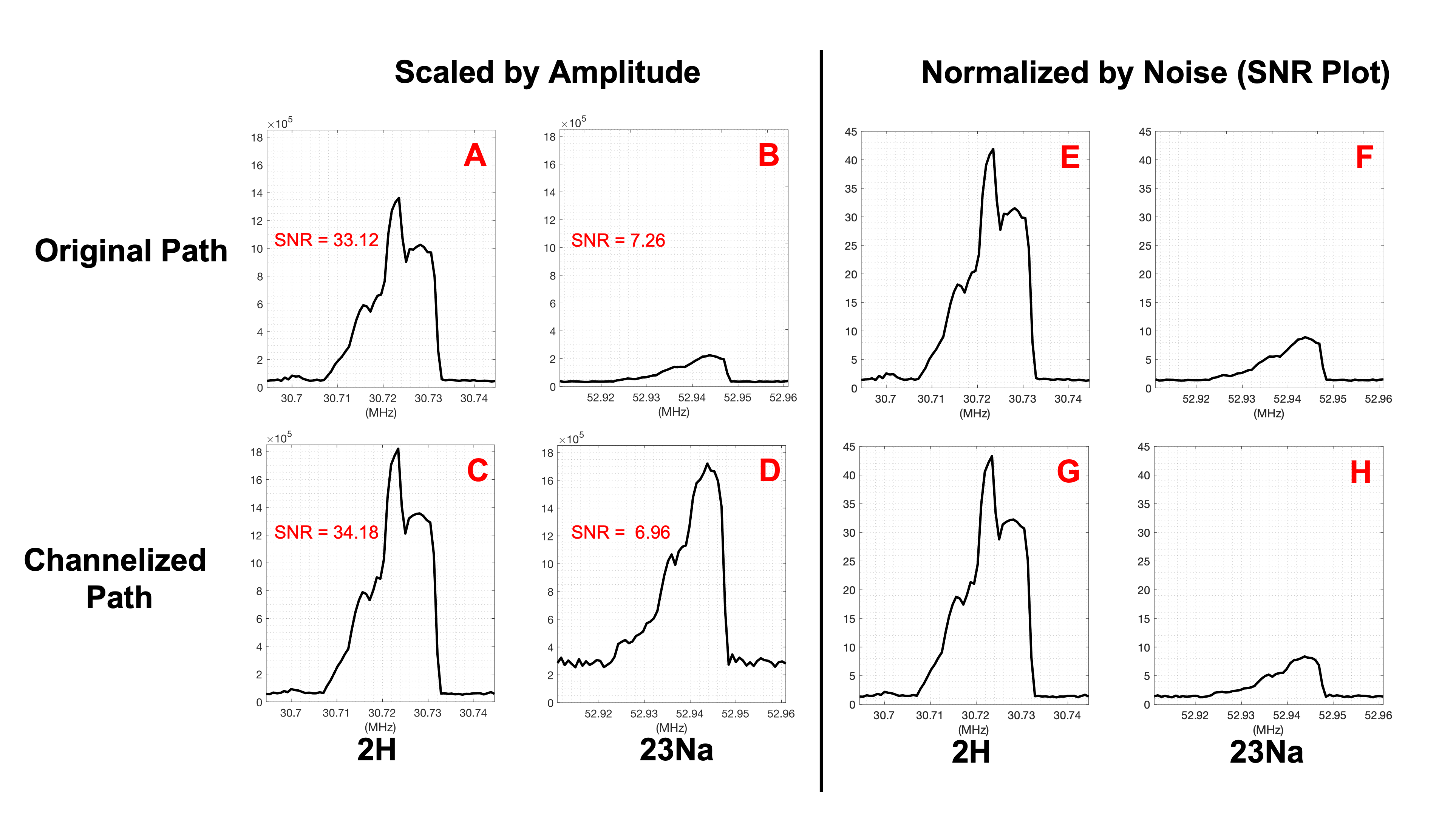
Figure 2: Results showing A) the original 2H profile, B) the original 23Na profile, C) the channelized 2H profile, and D) the channelized 23Na profile. The signals for both nuclei have clearly been boosted, but little disturbance in SNR is observed. For reference, the plots are normalized by their respective noise measurements in plots E) original 2H profile, F) original 23Na profile, G) channelized 2H profile and H) channelized 23Na profile.
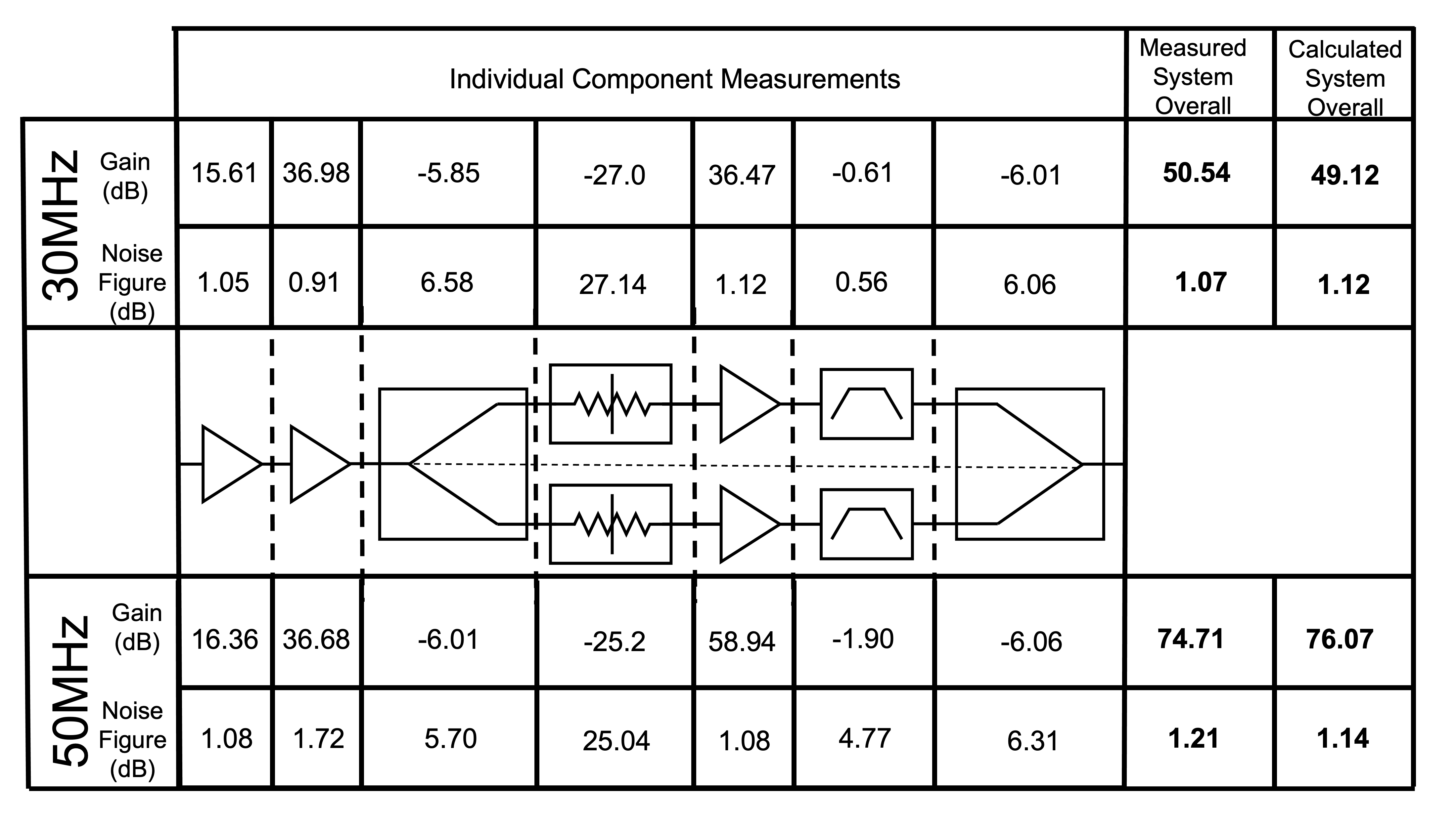
Figure 3: Table reflecting the measured noise figure and gain of the individual channels introduced, as well as the overall gain and noise figure for the combined channels. Both noise figure and gain are provided, even for passive devices, for the purposes of accuracy. The 60dB LNA was selected as the optimal available amplifier at the time of the work due to it’s low NF, but may have led to the suspected saturation in the 23Na channelized data. Further work will include optimization of this selection.
DOI: https://doi.org/10.58530/2023/5277