5272
Detecting Spine Movements with a Navigator Echo for Motion Correction of Spinal Cord fMRI1Department of Systems Neuroscience, University Medical Center Hamburg-Eppendorf, Hamburg, Germany
Synopsis
Keywords: Motion Correction, fMRI
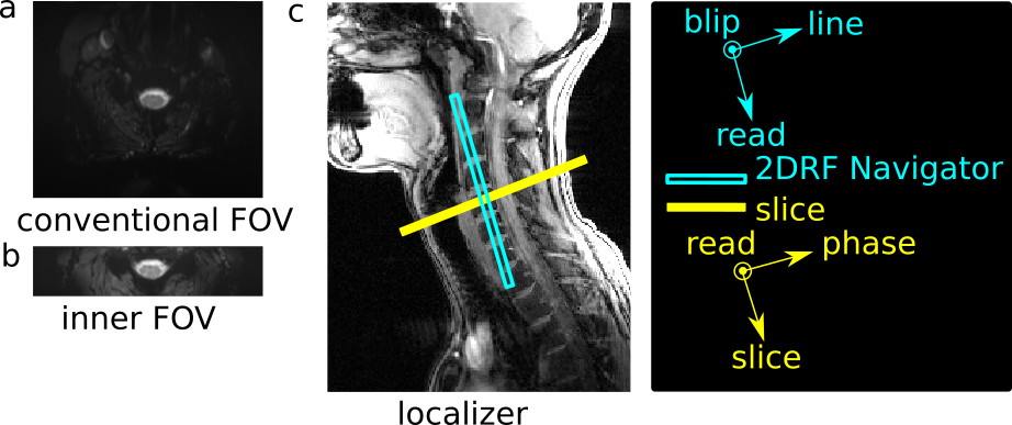
Motion correction is crucial for functional neuroimaging, however, not straightforward for applications in the cervical spinal cord because its shape, size, and inner structure barely vary along the cord’s axis. Previous spinal cord fMRI studies involved motion correction in this direction based on the vertebral disks visible in the fMRI acquisitions but for transverse slices, this approach suffers from a low spatial resolution (slice thickness typically 3.5mm or more). Here, a columnar navigator positioned along the spine is used to detect spine movements with a high spatial resolution that could be used for motion correction of spinal cord fMRI.Introduction and Motivation
The spinal cord is an important part of the central nervous system that performs processing of sensory input from the body and motor output signals and has been shown to play a crucial role in pain processing1. However, while displacements of the spinal cord in left-right or posterior-anterior direction can easily be identified within the images, movements along the cord’s axis are hard to identify because the anatomic structure of the spinal cord barely varies in this direction.Therefore, the intervertebral disc in fMRI acquisitions have been used2 as a proxy to estimate gross movements along the cord’s axis. However, this approach not only suffers from the limited spatial resolution of transverse fMRI data in this direction (slice thickness typically 3.5mm-5mm) but also is not compatible with inner-FOV imaging that may help to reduce geometric distortions in EPI-based fMRI (Fig. 1).
Here, it is shown that a navigator measurement of a columnar volume along the spine axis can be used to estimate spine movements in this direction with high spatial resolution. This approach not only provides a much better spatial resolution, i.e. precision of the obtained displacement, but also is compatible with inner FOV imaging. Thus, it could help to improve motion correction in spinal cord fMRI acquisitions.
Method
The basic geometric setup is sketched in Fig.1c. For the navigator, a columnar volume along the spine is used that is parallel to the spinal cord in the region-of-interest (vertebrae C5/C6). With frequency encoding applied along the column, an intensity projection of the column perpendicular to its axis is obtained. Due to the different spin densities and relaxation times, the projection allows to identify the intervertebral disc with the best delineation being obtained for those disc oriented perpendicular to the column, i.e. close to the spinal region-of-interest (Fig.1c).The basic pulse sequence is sketched in Figure 2. The navigator part applied prior to the echo-planar image acquisition involves a spatially two-dimensional selective RF (2DRF) excitation3, 4 based on a blipped-planar trajectory and a frequency-encoded data acquisition followed by a spoiler gradient pulse.
Measurements were performed on a 3T whole-body MR system (PrismaFit, Siemens Healthineers) using a 64-channel head-neck coil. Healthy volunteers were investigated after their informed consent was obtained. Experiments were performed with the volunteer instructed first to rest and then to move the head and neck back-and-forth along the head-feet direction. The 2DRF excitation (flip angle 10°) had a spatial resolution of 5×10mm2 (line×blip) with the blip direction oriented along the left-right direction with a field-of-excitation of 150mm in order to position unwanted side excitation outside of the body. To reduce Gibbs ringing, a Gaussian filter was applied to the RF envelope reducing the calculated amplitude values by 85% at the edges of excitation k-space. The navigator data were acquired with a bandwidth per pixel of 495Hz and a spatial resolution of 1mm covering a field-of-view of 128mm. The overall duration of the navigator part was 13.8ms per shot. With a single-slice mock EPI shot (data not stored) performed in-between, 128 navigator echoes were acquired with a temporal resolution of 200ms (total acquisition time 25.6s).
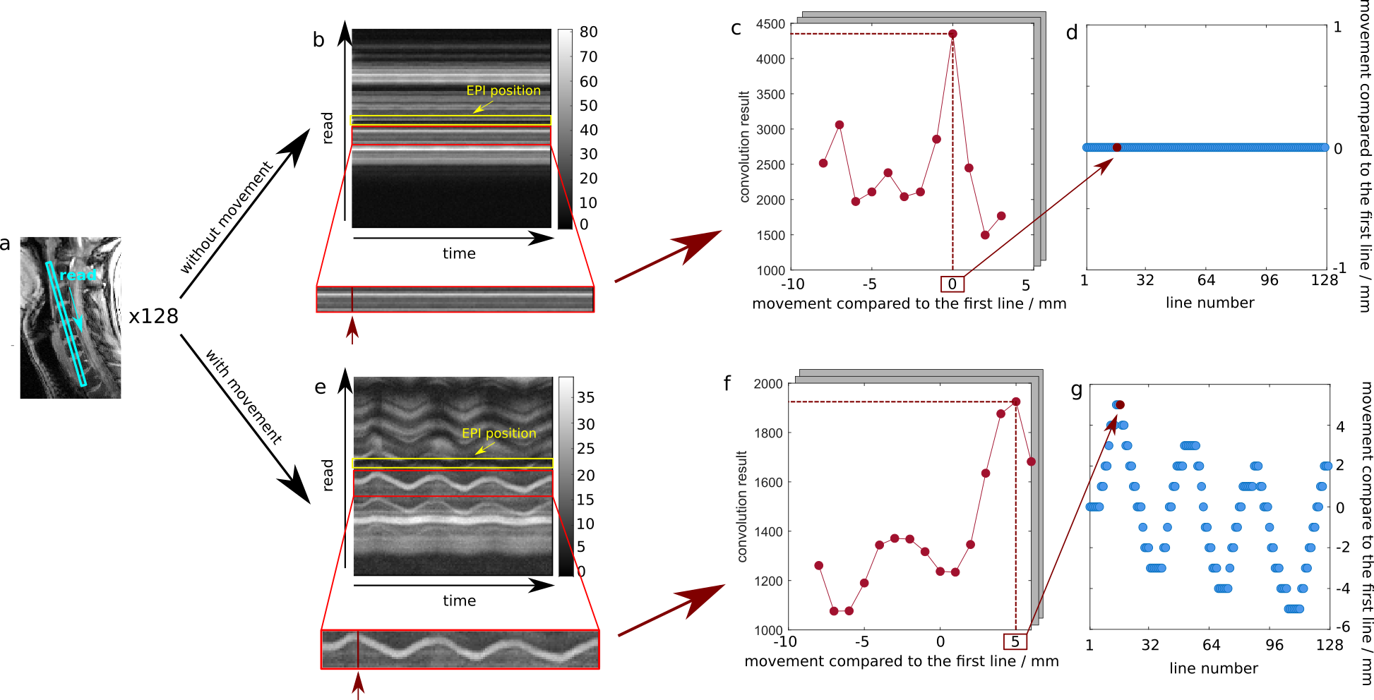
To detect motion, we followed the shift of a single intervertebral disc near the EPI slice which is shown as the yellow block in figure 3 (b, e). Only data within the red block is used. From the reference navigator line (first line), the intervertebral disc is defined as the voxels with an intensity greater than 0.7 times the maximum intensity value. The intensity vector of these voxels was flipped and defined as the reference vector for the 1-dimensional convolution. Afterwards, the convolutions between this reference vector and the subsequent lines were calculated. Through this, we can find the continuous voxels matching the reference vector the best for each subsequent line. Two example results are shown in figure 3 (c, f).
Results
Figure 3 shows the results. For the rest condition (Fig.3.b) the navigator signal is very stable in time with the target disc representing a straight line during the time series in Figure 3.d. In conclusion, the data analysis did not reveal any displacement. For the movement condition (Fig.3.e), the navigator signal from the target disc close to the EPI slice shows a periodic signal variation. The displacements (Fig.3.e) obtained from the data analysis clearly reflect this periodic movement.Discussion and Conclusion
These results show that a navigator along the spine can detect motion along the spine's axis with a high spatial and temporal resolution. These data could be used to perform motion correction of spinal cord fMRI data. Like previous approaches2 based on the fMRI data, it detects movements of the spine as a proxy of spinal cord displacements because no solution to identify spinal cord movements along the cord's axis directly has been presented so far. The navigator approach also provide a higher spatial resolution and is also compatible with inner-FOV imaging that may reduce geometric distortions for EPI. Extra time is needed for the navigator but a single navigator for each fMRI volume is only 13.8ms. Therefore, the navigator approach may help to improve motion correction in spinal cord fMRI.Acknowledgements
This research was supported by the German Research Foundation DFG (SFB936/A6).References
1. Eippert F, Finsterbusch J, Bingel U, Büchel C. Direct Evidence for Spinal Cord Involvement in Placebo Analgesia. Science. 2009; 326: 404
2. Tinnermann
A, Geuter S, Sprenger C, Finsterbusch J, Büchel C. Interactions between brain
and spinal cord mediate value effects in nocebo hyperalgesia.
Science.2017;358:105-108.
3. Bottomley PA, Hardy CJ. Two-dimensional spatially selective spin inversion and spin-echo refocusing with a single nuclear magnetic resonance pulse. J Appl Phys. 1987; 62: 4284-4290.
4. Pauly J, Nishimura D, Macovski A. A k-space analysis of small-tip-angle excitations. J Magn Reson. 1989; 81: 43-56.
5. Finsterbusch J, Eippert F, Büchel C. Single, slice-specific z-shim gradient pulses improve T2*-weighted imaging of the spinal cord. Neuroimage. 2012; 59(3): 2307-2315
Figures