5252
A Hardware Approach to Automatic Phase Correction in Receive-only Frequency Translation1Electrical and Computer Engineering, Texas A&M University, College Station, TX, United States, 2Biomedical Engineering, Texas A&M University, College station, TX, United States
Synopsis
Keywords: RF Arrays & Systems, System Imperfections: Measurement & Correction
Frequency translation has been demonstrated to enable X-nuclear array coils on systems with only narrow-band 1H receivers. Mixing on receive only is preferred given the SAR monitoring on the transmit side, but requires additional phase correction to perform signal averaging. A post-processing phase correction method has been previously introduced by our group using the signals coupled from the local oscillators (LO) on the host system and translator. To avoid any post-processing and improve scanner throughput, we implement this correction method with hardware to detect and compensate the phase shift during the scan, which allows the signal averaging on the scanner.Introduction
Many MRI scanners are equipped with multi-channel 1H receivers, but far fewer support multi-channel non-1H experiments. Due to the relatively low SNR comparing to 1H, it is often beneficial to apply receive coil arrays to multi-nuclear experiments. Frequency translation has been previously demonstrated to successfully implement X-nuclear array coils on systems with only narrow-band 1H receiver arrays 1, 2, 3. Receive-only frequency translation has the advantage of maintaining the integrity of SAR monitoring in the transmit chain. To perform receive-only frequency translation, pulse sequence modification is usually made to transmit at X-nuclei frequency and receive at 1H, as shown in Figure 1. The frequency change typically happens in the last stage LO of the scanner, and introduces a time-dependent phase shift to the acquired signal due to the use of different LO frequencies during transmit and receive. Left uncorrected, this introduces phase jitter in imaging data and disables system-based signal averaging for both imaging and spectroscopy experiments.Previously, a software-based phase correction method has been presented by our group, which successfully removes any phase jitter in images, and maintains the averaging ability for both low SNR spectroscopy studies and imaging studies 4. However, this method requires saving the individual FIDs (or echoes) off the scanner’s console, which prevents the usage of data processing tools on the scanner and adds to the study duration. To solve this issue, we implemented a hardware-based correction method to automatically perform phase corrections during the scan. Instead of recording phase information from both LOs for post-processing, the host system LO phase shift is measured in real-time and the translator LO is phase offset to compensate for the phase shift. With this implementation, the raw data is averaged and stored in the host system and can be viewed and processed directly. Initial testing of the phase correction hardware has been done with 23Na FIDs and the preliminary results are presented here.
Method
23Na MRS experiments were performed on a 40cm Varian 4.7T scanner. A saddle volume coil was used for RF power transmission, and a 10cm × 6cm rectangular surface coil was used for MR signal reception. A testing phantom containing NaCl solution was used for the experiment. A simple pulse-and-acquire sequence was used with 36 averages, where the transmit frequency was set at 23Na and receive frequency was set a 1H.In order to correct the phase shift during the scan, the phases of the system LO at both transmit and receive frequencies were detected using RF phase detectors (AD3802, Analog Devices, Inc., MA, USA). Four AD8302 devices were used to measure those two frequencies of the system LO, as two of the devices are required for full 360-degree phase measurements 5. Reference signals from the PTS frequency generators on the Varian were used as phase references for the AD8302. The phase correction coefficient was calculated from those two phases in every repetition. Before signal reception, the translator LO signal was generated with a phase offset equal to the phase correction coefficient, to both up-mix the received X-nuclei frequency signal to 1H frequency and compensate for the phase shift produced by the host system LO. The translator LO signal is generated by a direct digital synthesizer (DDS) (AD9959 Analog Devices, Inc., MA, USA). An Arduino UNO microcontroller (Arduino, Italy) was used to receive TTL triggers from the scanner, process phase information from the AD8302, and control the AD9959 for LO generation. The timing diagram of the phase correction hardware functionality is shown in Figure 2.
Result
Figure 3 shows the 23Na spectra acquired with 36 averages with the Varian stock system, as well as the spectra acquired with the receive-only frequency translator installed. When the phase correction is turned off in the microcontroller, the AD9959 generates the translator LO with zero phase offset in every repetition, which clearly disables averaging ability since the phase shift is not compensated. After turning on the phase correction, the translator LO is set to compensate the system host LO in every repetition, and signals can be averaged within the scanner as normal, transparent to the operator.Discussion and Conclusion
The presented hardware provides an approach to implement receive-only frequency translation without extra data post-processing. The acquired signal can be directly stored in the scanner, which allows us to use the scanner normally with receive-only frequency translation. In our previous method, the phase correction offset is depending on TR and TE, and any gating would have created a discontinuous phase change. The proposed phase correction system is designed to automatically correct for changes in TR, TE, or gating. Preliminary results show the feasibility of this method with simple pulse-and-acquire experiments at 23Na frequency with 36 averages. The next steps include implementing the technique in a circuit board rather than discrete components and extending to imaging.Acknowledgements
This research was funded by the NIH grant RO1EB028533.References
1. Ogier, Stephen E., et al. "A frequency translation system for multi-channel, multi-nuclear MR spectroscopy." IEEE Transactions on Biomedical Engineering 68.1 (2020): 109-118.
2. Lee, Ray F., et al. "A broadband phased‐array system for direct phosphorus and sodium metabolic MRI on a clinical scanner." Magnetic Resonance in Medicine: An Official Journal of the International Society for Magnetic Resonance in Medicine 43.2 (2000): 269-277.
3. Nixon et. al. Proc. ISMRM 2021, 3113;
4. Hou et. al. Proc. ISMRM 2022, 4969;
5. Sun, Chenhao, et al. "A retrofit to enable dynamic steering for transmit arrays without multiple amplifiers." Magnetic Resonance in Medicine 85.6 (2021): 3497-3509.
6. Viswanath, Madavan Raja, and Steven M. Wright. "Rapid MR Scanner Independent B1 Field Measurement System for Phased Arrays." 2022 44th Annual International Conference of the IEEE Engineering in Medicine & Biology Society (EMBC). IEEE, 2022.
Figures
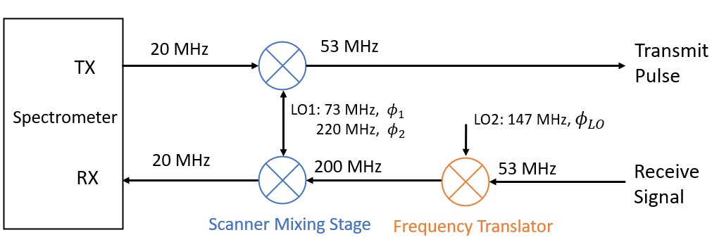
Figure 1: Simplified block diagram of receive-only frequency translation approach. The phase shift in the signal is resulted from the phase difference between Φ1 and Φ2 and the translator LO phase ΦLO.
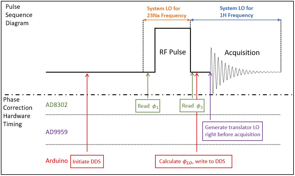
Figure 2. Pulse sequence and phase correction hardware timing diagram. Short delays are added after the frequency changes and before the RF pulse and acquisition, in order to allow time for phase detection, calculation and translator LO generation. The diagram is for demonstration purposes and not drawn to the actual time scale.
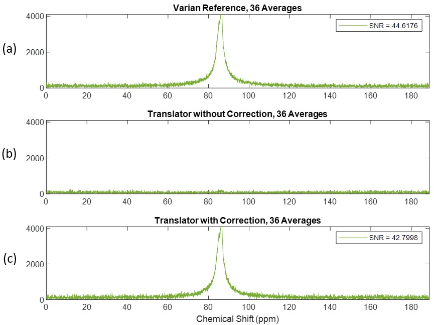
Figure 3. Spectra of 23Na acquired with 36 averages with (a) the Varian stock system, (b) receive-only translation without phase correction hardware enabled and (c) receive-only translation with the phase correction hardware enabled. All the data was averaged and stored in the Varian system without any post-processing. Minor SNR loss is noticed due to the additional mixer introduced by the translator.