5249
Toward the development of a B0 gradientless MRI system: Frequency-encoded Frequency-modulated Rabi Encoded Echoes.1Biomedical Engineering, University of Minnesota, Minneapolis, MN, United States, 2Center for Magnetic Resonance Research and Department of Radiology, University of Minnesota, Minneapolis, MN, United States, 3Centro de Imagens e Espectroscopia por Ressonância Magnética - Physics Institute of São Carlos, University of São Paulo, São Paulo, Brazil
Synopsis
Keywords: RF Pulse Design & Fields, Low-Field MRI, B1 Imaging
Frequency-encoded Frequency-modulated Rabi Encoded Echoes (FE-FREE) is a new method to perform spatial encoding using a B1 field gradient. FE-FREE is analogous to conventional frequency-encoding with a B0 gradient, except a B1 gradient is used. A first demonstration of FE-FREE is shown using the B1 gradient of a surface coil in a 0.5 T magnet with large B0 inhomogeneity (±3 ppm). Frequency encoding with FE-FREE is one approach that in the future might enable low cost MRI scanners without B0 gradient hardware and infrastructure.
Purpose:
The high cost of MRI systems relegates their clinical impact to a minority of the world. MRI remains inaccessible to ~90% of the world’s population1. Frequency-modulated Rabi Encoded Echoes (FREE) are a family of B1 encoding pulse sequences2-3. FREE aims to develop cheaper, quieter, and smaller MRI systems without B0-gradient coils. We present Frequency-Encoded (FE-) FREE which performs frequency encoding using a B1 gradient, samples using gapped pulses4, and promotes the removal of dedicated B0-gradient coils.Theory:
FREE uses adiabatic full passage (AFP) pulses to produce spin echoes insensitive to B0 and B1 inhomogeneity5. The accumulated phases of the transverse magnetization during the AFPs are spatially dependent and described by ψ(r,t)6:$$\psi(r,t) = \int_{0}^{t} \omega_{eff}(r,\tau) d\tau$$
$$\omega_{eff}(r,t) = \sqrt{(\omega_{1}^{max}(r)\cdot AM(t))^{2} + (A\cdot FM(t))^{2}} $$
where τ is a dummy integration variable; t is time; r is spatial distance; rmax is the field-of-view (FOV); Tp is pulse length; AM(t) and FM(t) are the AFP’s pulse amplitude- and frequency- modulation functions; A = BWΩ/2, where BWΩ is the pulse excitation bandwidth; and ω1max(r) is the peak value of γB1 at position r. ψ(r,t) is approximately linearly dependent2 on ω1max(r). In the current implementation, FE-FREE consists of two successive AFPs following an excitation pulse (Fig 1). The resulting spatial phase is defined by
$$\psi_{net} (r) = \psi_{dp} (r, T_{p}^{dp}) - \psi_{ro} (r, T_{p}^{ro})$$
Tpdp and Tpro define the lengths of the first and second AFPs. ψdp and ψro define the phase from the first and second AFP. Both pulses are transmitted with the same BWΩ, FM(t), and B1 gradient. By setting Tpro = 2Tpdp, a rotary echo centered at the middle of the second AFP is created. Hyperbolic secant (HS) pulses are used for both AFPs due to their smooth inversion profiles across B0 inhomogeneities7-8. Δk, defined as
$$ \Delta k(t) = \frac{d\psi_{ro}(r,t)}{dr}$$
varies throughout the HS pulses (Fig 2). Figure 2 shows that higher-order HS pulses (e.g. HS10) present lower variations in Δk. Delays of length τrd + τro are placed in between pulse elements (τp) of the second AFP. τrd is inserted to allow coil ring-down (Fig. 1), and data acquired during τro are used for reconstruction. Gapping minimally affects9 pulse performance and permits sampling of the rotary echo. In FE-FREE, signal is sampled while the second AFP executes a 180º rotation of the transverse magnetization. In the first (frequency-modulated) rotating frame, the transverse magnetization lacks the conjugate relationship found in a typical echo. The rotary echo splits into Mx, My, and Mz magnetization components. In a second reference frame rotating at the angular velocity defined by the effective field angle, α(t), the Mx and My contain a conjugate relationship (Fig 3), where α(t) is defined as
$$ \alpha(t) =arctan\left( \frac{AM(t)}{FM(t)}\right)$$
To reach the second rotating frame, a y-rotation matrix using α(t) of the peak γB1 is applied to the data. To apply the rotation, the transverse signal (Sxꞌ and Syꞌ) is sampled through traditional approaches, and the longitudinal signal, Szꞌ(t), by calculation,
$$ S_{z'} = S_{max} - S_{xy'}(t)$$
where Smax is the maximum of the transverse signal, Sxyꞌ(t). The object is reconstructed by Fourier transformation of the transverse signal in the second rotating frame (Sxꞌꞌ and Syꞌꞌ).
Methods
Simulations: A linear γB1 gradient of 8.5 kHz ∙ (5 cm)-1 was used. The first and second HS10 time-bandwidths were 0.012 s ∙ 2000 Hz and 0.024 s ∙ 2000 Hz, respectively. τp = 50 μs and τro = 50 μs, and data collection occurred during the middle 75% of the pulse. 300 points were reconstructed. Reconstructions of the central slice of the Shepp-Logan phantom10 were evaluated for on- and off-resonant cases.Experiments: A 5-cm surface coil transmitted a non-linear γB1 gradient of ~10 kHz ∙ (5 cm)-1. A 100 μs square pulse excited the spins. The first and second HS10 time-bandwidth products were 0.020 s ∙ 2,000 Hz and 0.040 s ∙ 2,000 Hz, respectively. τp = 80 μs, τrd = 50 μs, and τro = 5 μs.1 point was acquired per τro. The total acquisition period, including pulse elements and gaps, was 0.0675 s. α(t) was defined using a γB1 of 10 kHz. Data were acquired with a single Tx/Rx CIERMag Digital Magnetic Resonance Spectrometer operating at 0.5 T11-14. The 0.5 T Halbach magnet had no B0 gradient coils and a Larmor frequency variation of ± 5 kHz across the phantom. 450 points were reconstructed.
Results
Simulations demonstrated excellent agreement with the true object (Fig 4). Experiments demonstrated the ability to produce the necessary rotary echo in a highly inhomogeneous magnet with no B0 gradient coils, leading to a good reconstruction of the 1D object (Fig 5).Discussion
As shown here, FE-FREE requires only a B1 gradient and is tolerant of B0 inhomogeneity. At lower magnetic fields, merging FE- and phase-encoded (PE) - FREE may permit volumetric imaging without B0 gradient coils. The ability to use an inhomogeneous (small) magnet together with the elimination of B0 gradients promises to significantly cut costs and lead to a radically new class of MRI scanner in the future.Conclusions
FE-FREE presents a promising B1-encoding approach that enables the removal of dedicated frequency-encoding B0 gradient coils.Acknowledgements
This research was supported by the Minnesota Lions Diabetes Foundation, Schott Family, and Malcolm B. Hanson Endowed Chair in Radiology. Additional support was provided by the National Institutes of Health grants U01 EB025153 and P41 EB027061. E. Torres is supported by the NSF GRFP and CIC Fellowships.References
1. Geethanath S, Vaughan JT. Accessible magnetic resonance imaging: a review. J Magn Reson Imaging. 2019;49:e65-e77
2. Torres E, Froelich T, Wang P, et al. B1-gradient–based MRI using frequency-modulated Rabi-encoded echoes. Magn Reson Med. 2021;00:1–12.
3. Hoult DI. Rotating frame zeugmatography. J Magn Reson.1979;33:183-197. Geethanath S, Vaughan JT.
4. Garwood M. Et Al. Fast and quiet MRI using a swept radiofrequency. J Magn Reson. 2006;181:342-349.
5.DelaBarre L., Garwood M. The return of the frequency sweep: designing adiabatic pulses for contemporary NMR. J Magn Reson. 2001;153:155-177.
6. Lee Y, Et Al. New phase-based B1 mapping method using two-dimensional spin-echo imaging with hyperbolic secant pulses. Magn Reson Med. 2015;73:170-181.
7. Tannus A, Garwood M. Adiabatic pulses. NMR Biomed.1997;10:423-434.
8. Silver MS, Joseph RI, Hoult DI. Highly selective π/2 and π pulse generation. J Magn Reson. 1984;59:347-351
9. Djaudat Et Al. Gapped pulses for frequency-swept MRI. J Magn Reson. 2008;193:267-273.
10. Shepp LA, Logan BF. The Fourier reconstruction of a head section. IEEE Trans Nucl Sci. 1974;21:21-43.
11. Pizetta D, Lourenço G, Silva D, Vidoto E, Martins M, Tannús A. “Magnetic resonance system configuration and editing tools”. (2015); Toronto,Canada, p667-668
12.Tannús A, Pizetta D, Silva D, Vidoto E, Lourenço G, Martins M, inventors; Universidade de São Paulo, assignee. ToRM-IDE - Integrated development environment for magnetic resonance applications. Brazil patent BR512015001484-6. 2015.
13.Pizetta D, Shimada D, Falvo M, et al, inventors; PyMR - a framework for programming magnetic resonance systems. Brazil patent BR512019001829-0. 2017.
14. Pizetta D, Lourenço G, Silva D, Vidoto E, Martins M, Tannús A. Magnetic resonance system configuration and editing tools. presented at: IUPESM 2015: Wold congress on medical physics & biomedical engineering; Jun 7-12 2015; Toronto, Canada.
Figures
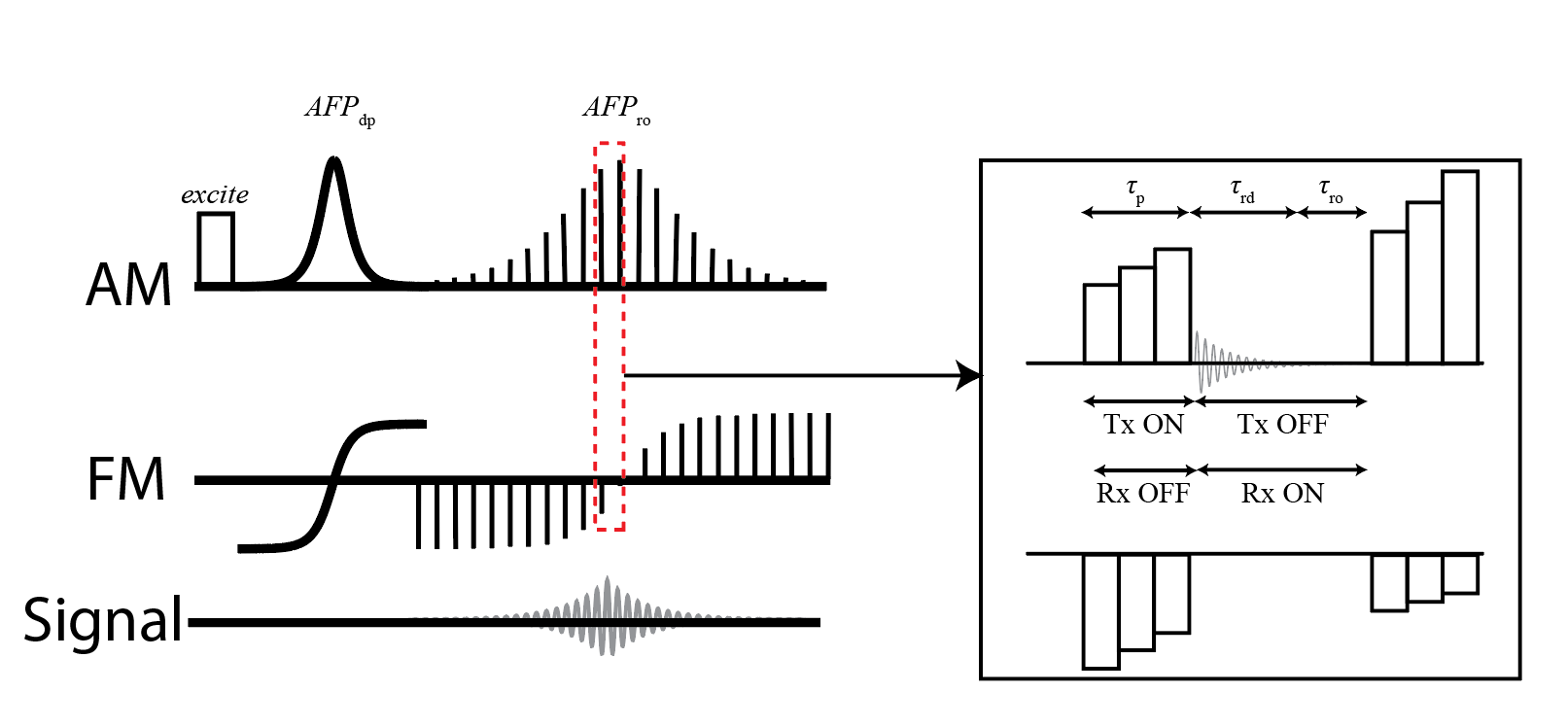
Figure 1: Pulse sequence used to frequency encode with B1 gradients. A rotary echo is created by setting the time-bandwidth product of AFPro to twice that of AFPdp. The rotary echo is centered during AFPro and gaps of length τrd + τro are inserted between pulse elements (τp). Data from τrd is avoided due to coil ring-down and data from τro is used to reconstruct the object. No B0 gradients are used for spatial encoding.
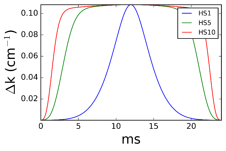
Figure 2: The calculated Δk of FE-FREE for an HS1, HS5, and HS10 pulse for a linear γB1 gradient of 9 kHz ∙ (5 cm)-1. The Δk approximately varied according to the shape of the amplitude modulation function. The center regions of an HS10 pulse permit sampling with an approximately constant Δk.
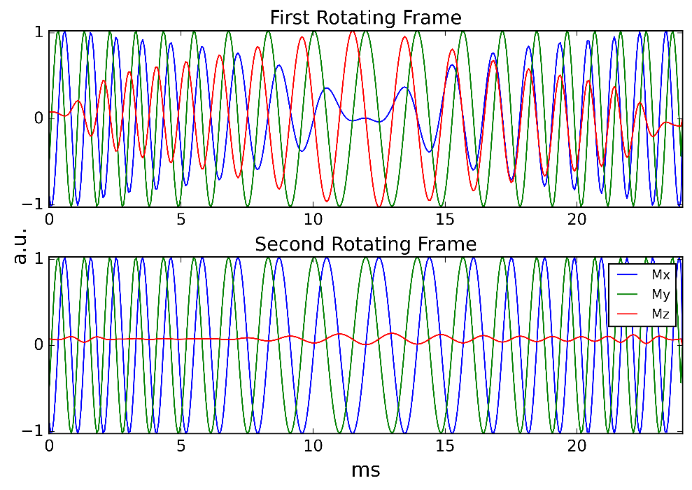
Figure 3: Figure 3: A signal from spins having a 500 Hz offset during the second adiabatic full passage of the FE-FREE pulse sequence (Fig 1). In the first rotating frame, the signal is made up of Mx, My, and Mz magnetization components. The Mx and My lack a conjugate relationships. The first rotating frame prevents a Fourier reconstruction. In a second rotating frame, Mx and My remain conjugates of each other. The Fourier transformation in the second rotating frame permits reconstruction of the signal.
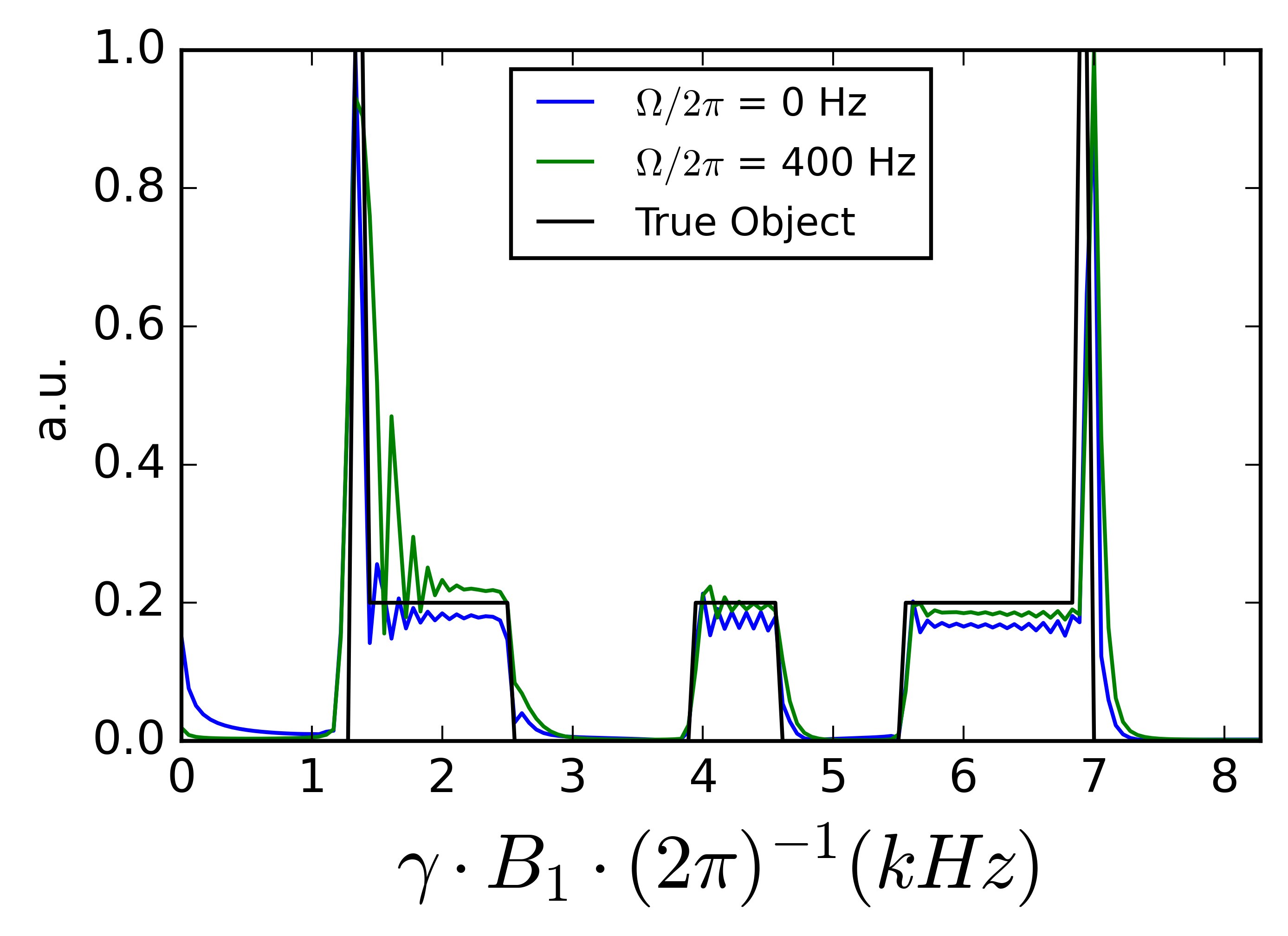
Figure 4: Simulation results for a 1D FE-FREE experiment with a linear γB1 gradient of 8.3 kHz∙(5 cm)-1. Ω/2π defines the B0 off-resonance in Hz. An on-resonance and off-resonant case was simulated. Off-resonance within the BW of the pulse produced minimal distortions.
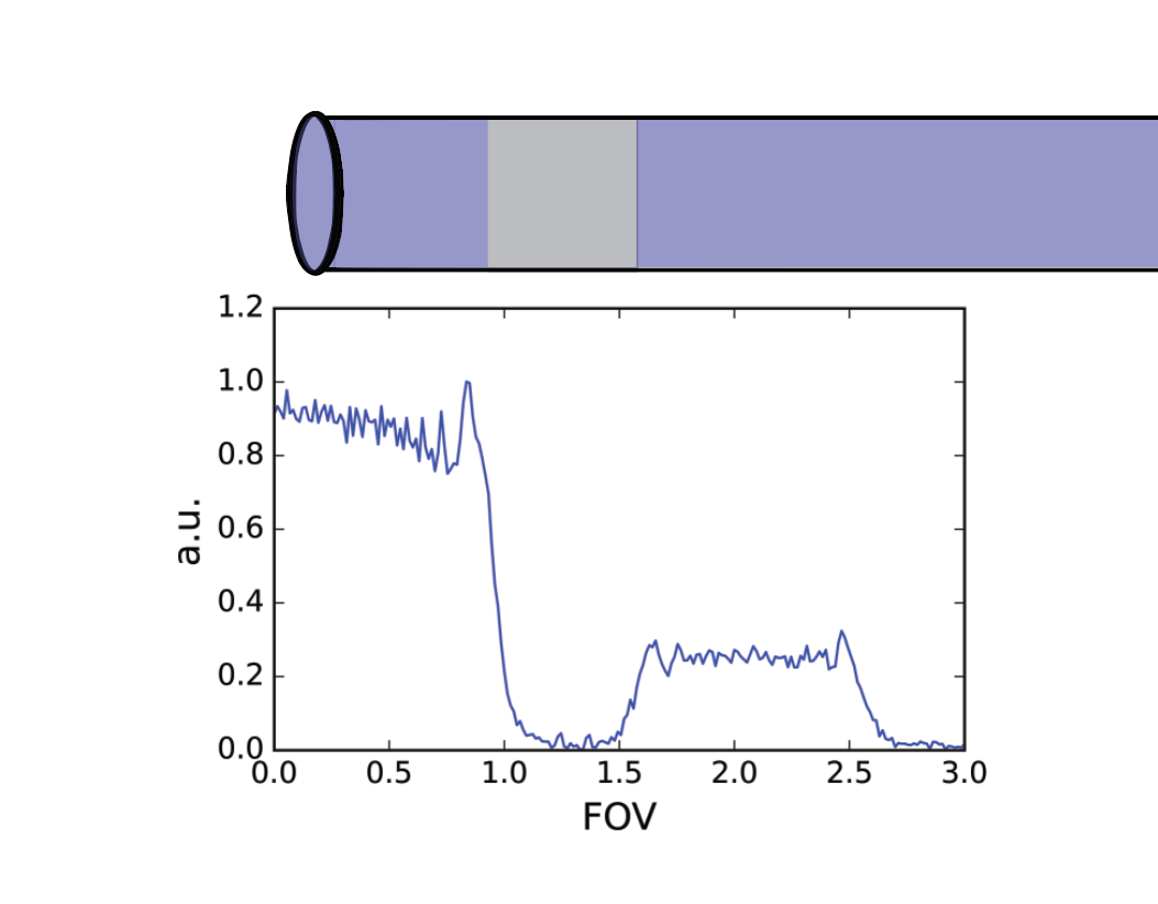
Figure 5: Experimental results for a 1D FE-FREE experiment. A 10 mL NMR tube phantom was placed in the center axis of a 5-cm surface coil. A Teflon plug (width = 5 mm) separated 2 water chambers. A visual representation is above the reconstruction. FE-FREE used a 0.5 T Halbach magnet with ± 5 kHz of B0 variation across the imaging volume and no B0 gradient coils. A nonlinear γB1 gradient of 10 kHz∙(5 cm)-1 transmitted AFPs and encoded the sample.