5231
Computer-controlled non-metallic phantom platform to simulate head motion with two degrees of freedom1Department of Mechanical & Aerospace Engineering, Carleton University, Ottawa, ON, Canada, 2Institute of Mental Health Research, The Royal Ottawa Mental Health Centre, Ottawa, ON, Canada, 3Department of Physics, Carleton University, Ottawa, ON, Canada
Synopsis
Keywords: Phantoms, Motion Correction, Dynamic phantom
A computer-controlled non-metallic head phantom platform was designed and constructed from 3D-printed parts. Driven by pneumatic stepper motors, the platform can simulate head motion with two degrees of freedom: tilting and rolling, with angular step resolution of 0.0833 degree and 0.227 degree, respectivily. A "neck/spine" design allows different static head phantoms to be mounted to the platform while still be able to fit inside standard head coils. The platform was tested on a PET/MRI scanner and successfully produced motion artifact with simulated motion.Introduction
MRI is an excellent modality for brain imaging thanks to its versatile capability to create soft-tissue contrast. Due to the relatively long image-acquisition time, MRI is prone to artifacts caused by patient motion1,2. Many motion techniques have been developed to compensate for or correct motion artifacts3–6. Phantoms that can simulate motion are needed either to investigate the motion artifacts or to develop motion correction technologies.Different approaches have been used to facilitate motion within a phantom study. Einspänner et al connected a pneumatically driven robot arm to a head phantom via a pole and string7. Gunther and Feinberg built a motion mechanism using a plastic toy construction set and connected it to their phantom through a rod8. These improvised systems are limited to their specific equipment and studies. General purpose MRI-compatible linear motion stages exist9,10. However, the phantom needs to sit on top of these platforms and the setup does not fit inside the head coils. In addition, the linear motion does not really represent typical head motion. Bones and Maclaren built a motion platform for their Shepp-Logan head phantom for MRI11. The platform can produce repeatable translation and rotation driven pneumatically by two syringes. The limitation of such a platform is that only the start and end positions are well-defined. Currently, there are MRI-safe dynamic phantoms that are commercially available (CIRS Zeus MRgRT Motion, UASAR™ MRI4D). These are abdominal phantoms and are mainly used for simulating respiratory motion.
In this abstract, we present a computer-controlled non-metallic 3D-printed platform that can simulate head motion with two degrees of freedom driven by pneumatic stepping motors.
Material and Methods
Pneumatic motorsTwo 3D-printed pneumatic stepper motors are used to provide accurately controlled motion. The motor design was adapted from the rotary stepping motor (R80) designed by Groenhuis and Stramigioli9. Some changes were made to the housing and the axle of the original design so the motors can be integrated into the motion platform. To improve the angular resolution, a custom planetary gear setup was created to provide a 1:4 gear reduction in an extremely thin manner. With the planetary gear, the motor assembly can provide an output rotation step resolution of 2.5 degrees. The current design can achieve a maximum of 30 steps per second using 5 m long tubing with a compressed air pressure of 0.4 MPa.
The platform
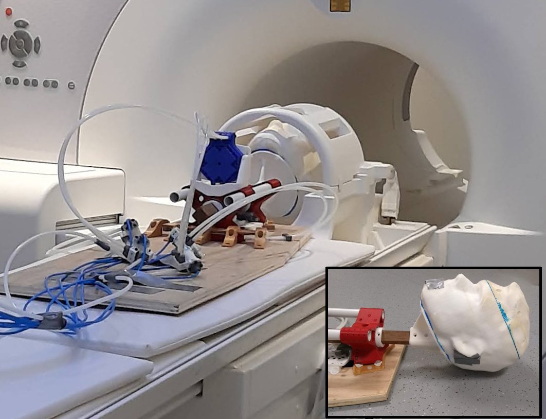
The motion platform (Fig. 1) can be separated into two main assemblies. The base assembly includes two circular guide rails and a stepper motor that sways the upper assembly laterally, i.e. tilting motion with a range of 15 ̊ at a resolution of 0.0833 ̊. The upper assembly includes a 1 inch x 1 inch wood shaft that serves as the “neck/spine” to support different head phantoms, and a mechanism that provides rolling motion with a range of 30 ̊ at a resolution of 0.227 ̊. Such a design allows head phantoms to be suspended and moved inside standard head coils.
The phantom
A hollow head phantom was produced using 3D printing. The phantom can be secured to the wood shaft with nylon screws (Fig. 2 insert). Different phantom holders could be designed and printed for other phantoms. To test the platform, a pineapple was inserted into the hollow head phantom to provide some contrast that could well represent motion.
Platform Control
Each stepper motor is controlled using three 5/2 valves, two to control motion and one to toggle the air supply to the motor. The valves are controlled by a microcontroller (Raspberry PI®) through MOSFET transistors. A python program is used to control the robot. A graphic user interface (GUI) enables the user to control the range and speed of the two motions, tilting and rolling. A multithreading technique allows the platform to perform the two motions simultaneously.
Testing the platform
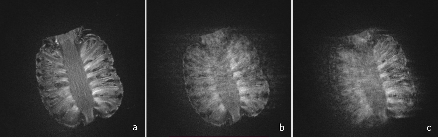
The platform with the head phantom was placed on the bed of a Siemens Biograph mMR 3.0 T PET/MRI scanner (Fig. 2). The head phantom was suspended in the head coil. Multi-echo MPRAGE sequences12 (TR = 2080 ms, 4 echoes, TE = 1.7 – 6.8 ms, TI = 1050 ms, FOV = 256 mm, 256x256, 192 slices, thickness = 1 mm) were acquired under three motion conditions: a) static, b) phantom tilting from -3.5 ̊ to 3.5 ̊ at a speed 0.5 deg/sec, and c) phantom rolling from -11.4 ̊ to 11.4 ̊ at a speed of 0.454 deg/sec.
Results
Figure 3 shows examples of MRI images acquired under the three conditions. Motion artifacts are clearly visible as the platform simulates a tiling motion (Fig. 3b) and a rolling motion (Fig. 3c).Conclusion
A computer-controlled non-metallic head phantom platform was designed and constructed. Driven by pneumatic stepper motors, the platform was able to simulate head motion with two degrees of freedom. The platform was tested on a PET/MRI scanner and successfully produced motion artifacts with simulated motion.Acknowledgements
This project is supported by Carleton University Development Grant and Carleton University Campus Co-op Employer Fund.References
1. Afacan, O. et al. Evaluation of motion and its effect on brain magnetic resonance image quality in children. Pediatr. Radiol. 46, (2016).
2. Zaitsev, M., Maclaren, J. & Herbst, M. Motion artifacts in MRI: A complex problem with many partial solutions. Journal of Magnetic Resonance Imaging 42, 887–901 (2015).
3. Johnson, P. M. et al. Rigid-body motion correction in hybrid PET/MRI using spherical navigator echoes. Phys. Med. Biol. 64, 08NT03 (2019).
4. Zaitsev, M., Dold, C., Sakas, G., Hennig, J. & Speck, O. Magnetic resonance imaging of freely moving objects: prospective real-time motion correction using an external optical motion tracking system. Neuroimage (2006). doi:10.1016/j.neuroimage.2006.01.039
5. Zaitsev, M., Akin, B., LeVan, P. & Knowles, B. R. Prospective motion correction in functional MRI. Neuroimage (2017). doi:10.1016/j.neuroimage.2016.11.014
6. Maclaren, J., Herbst, M., Speck, O. & Zaitsev, M. Prospective motion correction in brain imaging: A review. Magn. Reson. Med. (2013). doi:10.1002/mrm.24314
7. Einspänner, E. et al. Evaluating different methods of MR-based motion correction in simultaneous PET/MR using a head phantom moved by a robotic system. EJNMMI Phys. 9, 1–17 (2022).
8. Günther, M. & Feinberg, D. A. Ultrasound-guided MRI: Preliminary results using a motion phantom. Magn. Reson. Med. 52, 27–32 (2004).
9. Tavallaei, M. A., Johnson, P. M., Liu, J. & Drangova, M. Design and evaluation of an MRI-compatible linear motion stage. Med. Phys. 43, 62–71 (2016).
10. Nofiele, J. et al. An MRI-compatible platform for one-dimensional motion management studies in MRI. Magn. Reson. Med. 76, 702–712 (2016).
11. Bones, P. & Maclaren, J. A physical Shepp-Logan head phantom for MRI. in Proceedings of Image and Vision Computing 317–320 (2007).
12. van der Kouwe, A. J. W., Benner, T., Salat, D. H. & Fischl, B. Brain morphometry with multiecho MPRAGE. Neuroimage 40, 559–569 (2008).
Figures