5225
Do anthropomorphic phantoms enhance compliance with the professional bodies' quality assurance guidelines for MRI in radiotherapy
Meshal Alzahrani1,2, David Broadbent3, Irvin Teh1, Bashar Al-Qaisieh3, Adrian Walker4, Rachel Lamb4, and Richard Speight3
1Leeds Institute of Cardiovascular and Metabolic Medicine, University of Leeds, Leeds, United Kingdom, 2Department of Diagnostic Radiology, Faculty of Applied Medical Sciences, King Abdulaziz University, Jeddah, Saudi Arabia, 3Department of Medical Physics and Engineering, Leeds Teaching Hospitals NHS Trust, Leeds, United Kingdom, 4Leeds Test Objects, Boroughbridge, United Kingdom
1Leeds Institute of Cardiovascular and Metabolic Medicine, University of Leeds, Leeds, United Kingdom, 2Department of Diagnostic Radiology, Faculty of Applied Medical Sciences, King Abdulaziz University, Jeddah, Saudi Arabia, 3Department of Medical Physics and Engineering, Leeds Teaching Hospitals NHS Trust, Leeds, United Kingdom, 4Leeds Test Objects, Boroughbridge, United Kingdom
Synopsis
Keywords: Phantoms, Radiotherapy
With the increasing use of magnetic resonance imaging (MRI) in radiotherapy (RT), guidelines for the use of MRI in RT have recently been published, including recommendations for quality assurance (QA) tests. This project investigates whether anthropomorphic phantoms can be more beneficial to comply with these guidelines compared to other phantoms. The performance of the anthropomorphic phantom has been compared to other phantoms. The anthropomorphic phantom has been shown to be useful in QA for MRI-CT registration and end-to-end test that cannot be performed by other phantoms.Introduction
Interest in MRI in radiotherapy (RT) has increased due to its unique advantages such as excellent soft tissue contrast. In 2021, the Institute of Physics and Engineering in Medicine (IPEM) and the American Association of Physicists in Medicine (AAPM) published guidelines for using MRI in RT1,2, including recommendations for quality assurance (QA) tests. This project aimed to evaluate whether anthropomorphic phantoms enhance compliance with these professional bodies’ quality assurance guidelines for MRI in RT as compared to other phantoms.Methods
Three phantoms were used in this project: an anthropomorphic multimodality head and neck phantom, an American College of Radiology (ACR) large MRI phantom, and a vendor MRI QA phantom, which is a homogeneous phantom. The following tests were carried out:1. Magnetic Field Drift test
The central frequency values were obtained using all phantoms via the method described in the guidelines.
2. Transmitter and Gain Calibration
T1 relaxation times were calculated for each phantom to determine the appropriate repetition time (TR) to use with each of them. The automatic and manual transmitter gain values were obtained using all phantoms via the method described in the guidelines. Then, the difference between automatic and manual transmitter gain values was compared.
3. Radiofrequency Coil Evaluation
Signal-to-noise ratio (SNR), Percent Image Uniformity (PIU), and percent signal ghosting (PSG) values were calculated using all phantoms.
4. SNR/image quality/ when employing RT accessories
Two scans were obtained for all phantoms. The first scan was performed without the use of RT accessories, and the second was performed with RT accessories. The clinical sequences used at our institution were used. SNR, PIU, and PSG values were calculated using all phantoms.
All MRI experiments were performed with a 3T Siemens Prisma MRI scanner (Siemens Healthineers, Germany). Tests 1, 3 and 4 were repeated twice immediately upon completion, without changes to the phantom setup, and then, they were repeated twice more with repositioning the phantom. The coefficient of variation (CoV) was calculated for both cases.
5. QA for MRI-Computed tomography (CT) registration
CT scans were obtained using a Phillips Brilliance Big Bore CT simulator (Philips Medical Systems, The Netherlands) for the anthropomorphic and ACR phantoms. Then, the CT and MRI obtained for the phantoms in the treatment position were rigidly registered within Raystation (RaySearch, Sweden). To calculate the dice similarity coefficient (DSC), a contour of the structure in the middle of the ACR phantom and the brain in the anthropomorphic phantom (Figure 1) was drawn. The contour was repeated two times to calculate the CoV.
6. End to end
After completing the image registration, a treatment plan was created for the anthropomorphic phantom and ACR phantom within Raystation to deliver 2 Gy to the target volume (Figure 1). The radiation dose will be delivered to the ionisation chamber in the anthropomorphic phantom to compare the measured dose with the planned dose.
Results
1. Magnetic Field Drift testIt was possible to find the value of the central frequency from all the phantoms. Figure 2 shows the CoV between the central frequency values obtained from each phantom.
2. Transmitter and Gain Calibration
T1 relaxation times of the vendor phantom, ACR phantom, and anthropomorphic phantom were 100, 145.7, and 1200 ms, respectively. Table 1 compares the automatic and manual transmitter gain values obtained from the phantoms.
3. Radiofrequency Coil Evaluation
Figure 3 shows the CoV between the results of SNR, PIU, and PSG for each phantom.
4. SNR/image quality/ when employing RT accessories
Figure 4 shows the CoV between the results of SNR, PIU and PSG without RT accessories and with RT accessories for each phantom.
5. QA for MRI-CT registration
The CoVs between the DSC values were 0.16 and 1.36 for the ACR and anthropomorphic phantom, respectively.
6. End to end
A treatment plan for the anthropomorphic and ACR phantom has been successfully created. The anthropomorphic phantom can accommodate a dosimeter, while the ACR phantom cannot. Work is ongoing to complete this test.
Discussion
This project demonstrated that the anthropomorphic phantom can be used in tests such as the magnetic field drift and in evaluating SNR, PIU and PSG, like other phantoms. As for the transmitter and gain calibration test, the differences between automatic and manual transmitter gain calculated using the anthropomorphic phantom and ACR phantom were large as compared to the difference calculated using the vendor phantom. Therefore, the anthropomorphic and ACR phantoms are not ideal for this test.Regarding QA for MRI-CT registration, the ACR phantom has much clearer structures than the anthropomorphic phantom. The brain contrast in the CT anthropomorphic phantom images is less pronounced than the structures of the ACR phantom (Figure 1). This may lead to a less accurate contour drawing when using the anthropomorphic phantom. However, the anthropomorphic phantom appears superior to the other phantoms in terms of QA for MRI-CT registration and the end-to-end test because the complexity of the phantom is more representative of the patient and a dosimeter can be placed inside the phantom.
Conclusion
The anthropomorphic phantom is important in QA procedures for MRI in RT, especially in QA for MRI-CT registration and end-to-end tests, and can be considered a complement to the other phantoms.Acknowledgements
No acknowledgement found.References
- Speight, R., Dubec, M., Eccles, C.L., George, B., Henry, A., Herbert, T., Johnstone, R.I., Liney, G.P., McCallum, H. and Schmidt, M.A. IPEM topical report: guidance on the use of MRI for external beam radiotherapy treatment planning. Physics in Medicine & Biology. 2021, 66(5), p.055025.
- Glide‐Hurst, C.K., Paulson, E.S., McGee, K., Tyagi, N., Hu, Y., Balter, J. and Bayouth, J. Task group 284 report: magnetic resonance imaging simulation in radiotherapy: considerations for clinical implementation, optimization, and quality assurance. Medical physics. 2021, 48(7), pp.e636-e670.
Figures
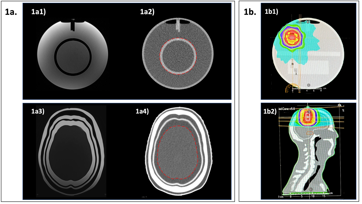
Figure 1 1a. MRI and CT images of ACR phantom and anthropomorphic phantom. 1a1) Axial MRI image of ACR phantom, 1a2) Axial CT image of ACR phantom, 1a3) Axial MRI image of anthropomorphic phantom and 1a4) Axial CT image of anthropomorphic phantom. Dashed contour lines show structures that have been contoured to calculate DSC. 1b. Radiation-treatment-planning CT scans. 1b1) Axial image of ACR phantom and 1b2) sagittal reconstruction of anthropomorphic Phantom. Colour wash display shows the dose distribution.
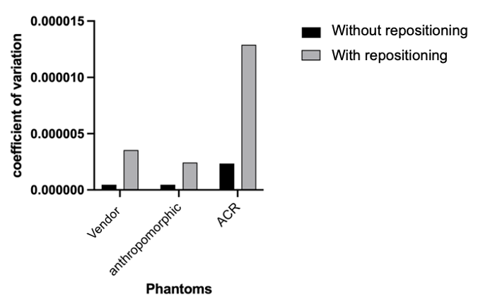
Figure 2 The CoV between the central frequency values obtained from each phantom.
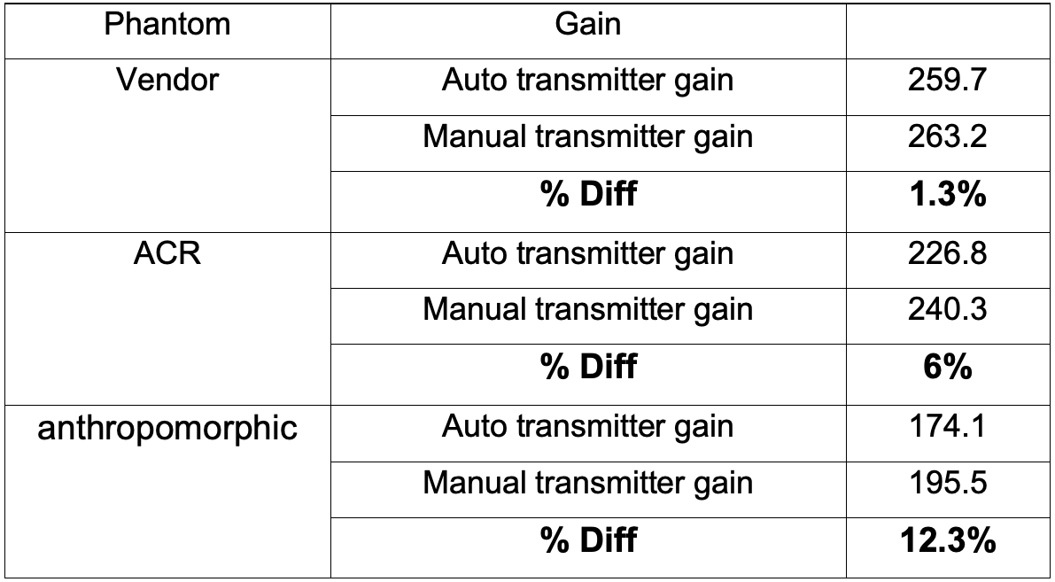
Table 1 Automated and manual transmitter gain values and the percentage difference between them for all phantoms.
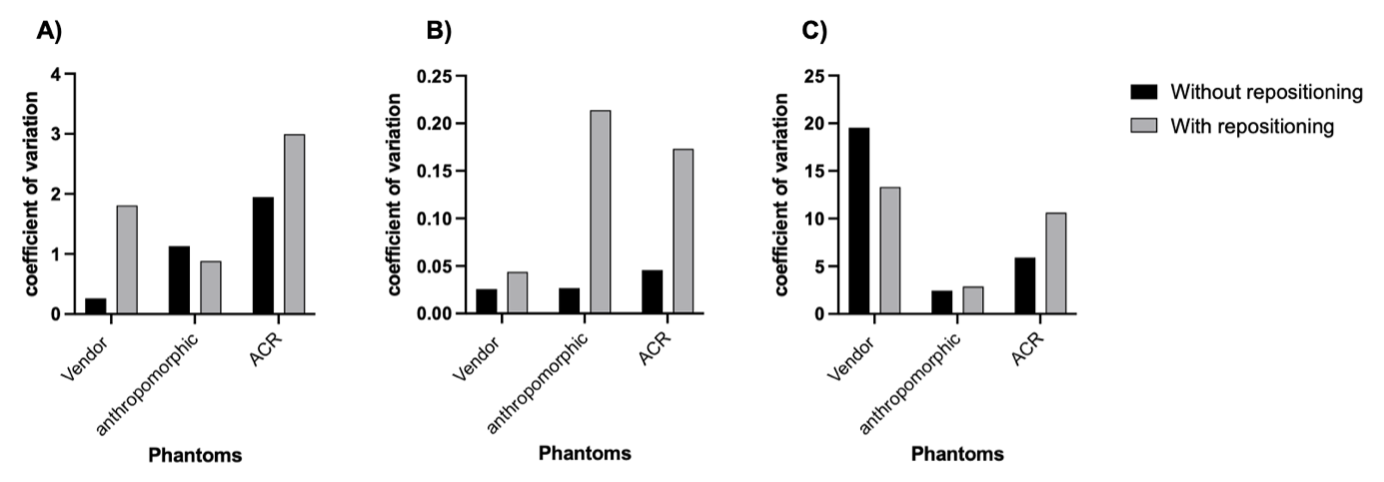
Figure 3. The CoV between the results of A) SNR, B) PIU and C) PSG of each phantom
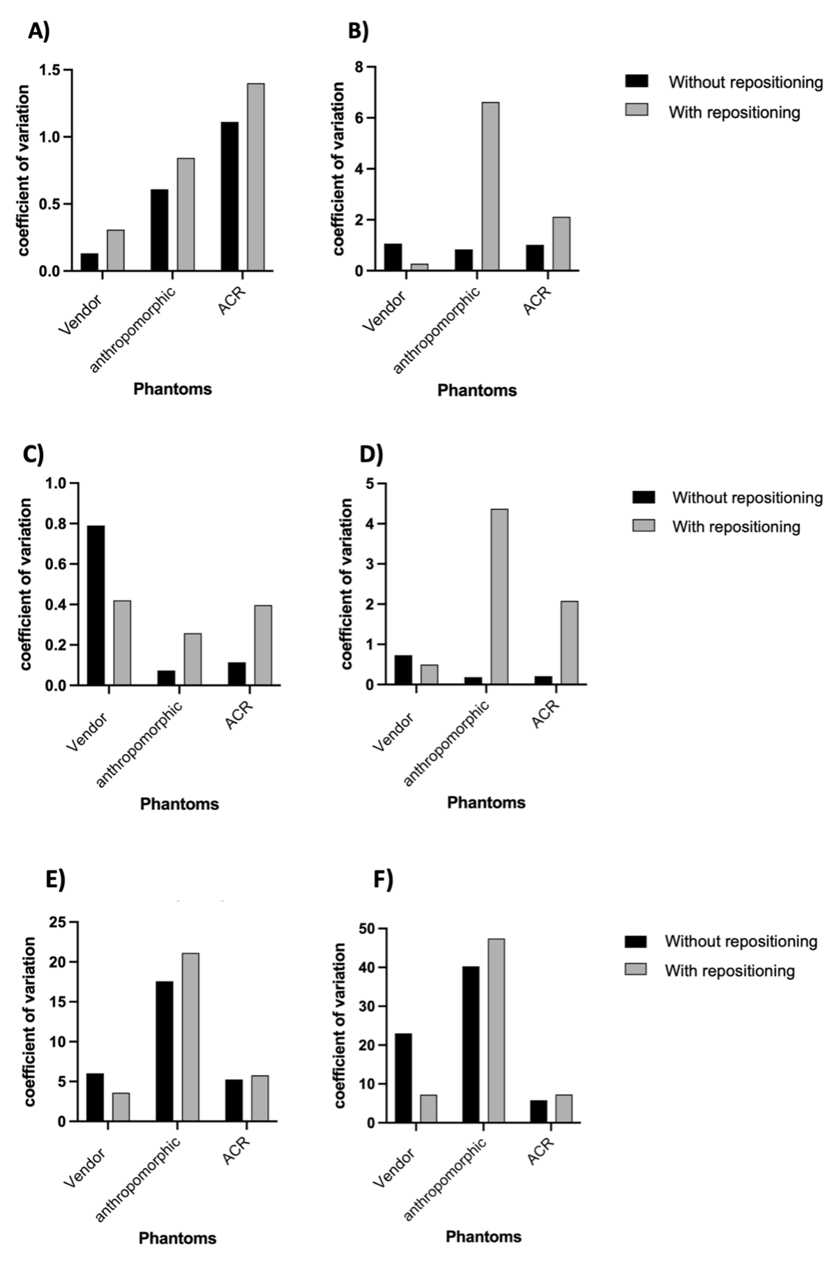
Figure 4 The CoV between the results of A) the SNR without RT accessories, B) the SNR with RT accessories, C) the PIU without RT accessories, D) the PIU with RT accessories, E) the PSG without RT accessories and F) the PSG with RT accessories
DOI: https://doi.org/10.58530/2023/5225