5219
Gradient Non-Linearity Calibration for Improved Spatial Position Accuracy with a High-Performance Gradient Using a Fiducial Phantom1GE Research, Niskayuna, NY, United States, 2Mayo Clinic, Jacksonville, FL, United States, 3Mayo Clinic, Rochester, MN, United States
Synopsis
Keywords: System Imperfections: Measurement & Correction, System Imperfections: Measurement & Correction, Gradient Non-Linearity; Spatial Fidelity; High Performance Gradients
Spatial encoding in MR-systems is subject to gradient non-linearity. If ignored or inadequately calibrated during system install, non-linear gradient fields manifest as spatial distortions impacting image quality, diminish accuracy for applications requiring MR guided intervention and introduce systematic errors in quantitative imaging such as diffusion MRI. High-performance, high-efficiency gradient systems, such as MAGNUS, require accurate calibration for imaging precision. In this study, a fiducial phantom was utilized to characterize and correct for residual distortions after standard gradient calibrations. Results highlight that distortion due to gradient non-linearity can be successfully reduced by phantom-based calibration for improved accuracy inline with QC metrics.Introduction
Spatial encoding fields in MR systems are inherently non-linear, with certain design/engineering trade-offs requiring the constraints for gradient non-linearity (GNL) to be intentionally relaxed in-lieu of higher gradient amplitudes and slew rates, reduced eddy currents and/or higher PNS thresholds1,2. Typically, in whole-body systems with larger design field-of-view (FOV), GNL artifacts appear subtle, and distortions manifest largely near the edge of the FOV. Here, odd-order spherical harmonic terms up to the 5th order are sufficient to parametrize gradient fields. However, systems with high-performance asymmetric, transverse gradients such as the compact 3T3 and specialized head-only gradients4–7 exhibit complex non-linear gradient fields and require higher-order, and both odd- and even-order terms to adequately model the gradient field8. Furthermore, inserts such as the MAGNUS4 have high gradient amplitude efficiency (~0.32 mT/m/A) and require high precision in calibration of the gradient driver settings. In such systems, standard systems calibrations are insufficient as they do not have sufficient degrees of freedom to capture spatially-varying non-linear fields.Notably, with higher gradient amplitudes, non-linear spatially-varying fields introduce systematic inaccuracies in contrasts such as in diffusion MRI, where $$$b\ \propto\ G^2$$$, resulting in spatially varying b-values, that can be corrected if gradient non-linearity is well-characterized9. Spatial distortions from GNL are of concern for various applications such as MR-guided interventions, radiation therapy and neurosurgical planning, as well as detection of subtle changes in brain morphology/volumetry associated with disease progression in longitudinal studies. In clinical representations such as Alzheimer’s disease, small volume changes are especially susceptible as the patient position may vary in longitudinal studies10–12.
Spatial fidelity is a key performance criterion for MR systems, and previous studies have improved relative distortions by either characterizing field decomposition or by using design-based gradient field maps for pixel-wise distortion correction. In this study, a dedicated fiducial phantom was utilized to explicitly characterize and correct for absolute residual GNL by re-calibrating the gradient coil gain. Systematically offsetting the phantom allowed for displacement in marker position, a standard metric for quantitative image accuracy, to be determined over 26-cm design FOV.
Methods
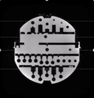
Fiducial Phantom: Distortions from GNL were characterized using the EMR128(Phantom Lab,Greenwich,NY)11, an 18-cm sphere containing 221fiducials at fixed positions.MR Acquisition: All acquisitions utilized a 3.0 T GE MRI (GE HealthCare, Waukesha, WI, USA), equipped with a MAGNUS insert (GE Research, Niskayuna, NY), using a single transmit-receive birdcage coil. The phantom was scanned with and without Gradwarp, a standard, vendor-supplied GNL correction, using a fast spoiled gradient-echo (3D FSPGR) sequence. The acquisition parameters were: receiver bandwidth=±62.5 kHz, readout direction=S/I, matrix=256x256, 1.0-mm isotropic resolution, TR/TE=4.1/1.5 ms, flip angle=11˚, 252 slices. To cover the entire 26-cm diameter spherical volume (DSV) for the gradient coil, the 18-cm phantom was systematically re-positioned using a custom designed rig which allowed for ±5 cm directional offsets (from isocenter) in the RL/AP/SI directions. An American College of Radiology (ACR) phantom was additionally scanned using the ACR test protocol with default and fiducial-based gradient calibrations.
Image Analysis: Associated software tool (SMARI, Phantom Lab) was utilized to track fiducial positions by establishing a local coordinate space, and template based correlation. MATLAB was used to generate displacement maps with the spatial distortion summarized as a displacement of measured versus known/actual fixed marker positions. Optimal gradient calibration factors can be determined by a simple linear regression to minimize residuals.
Results & Discussion
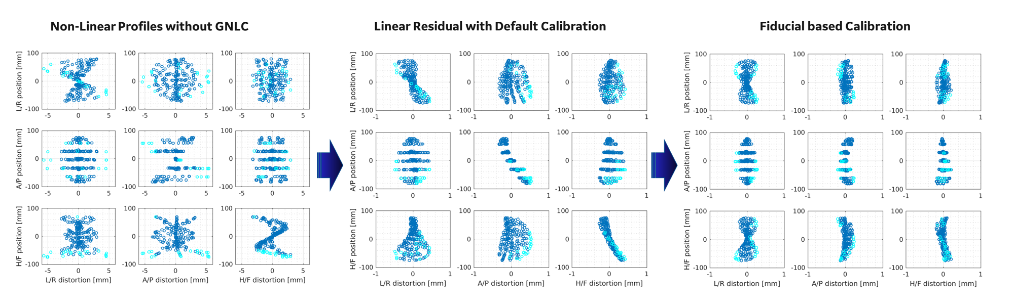
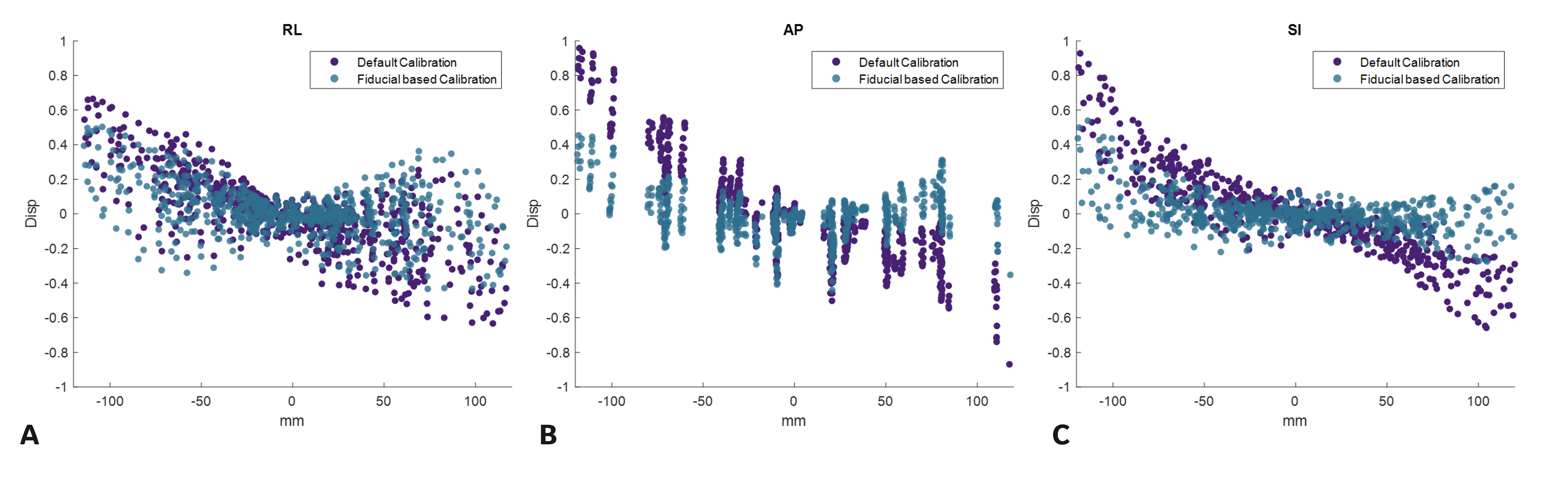
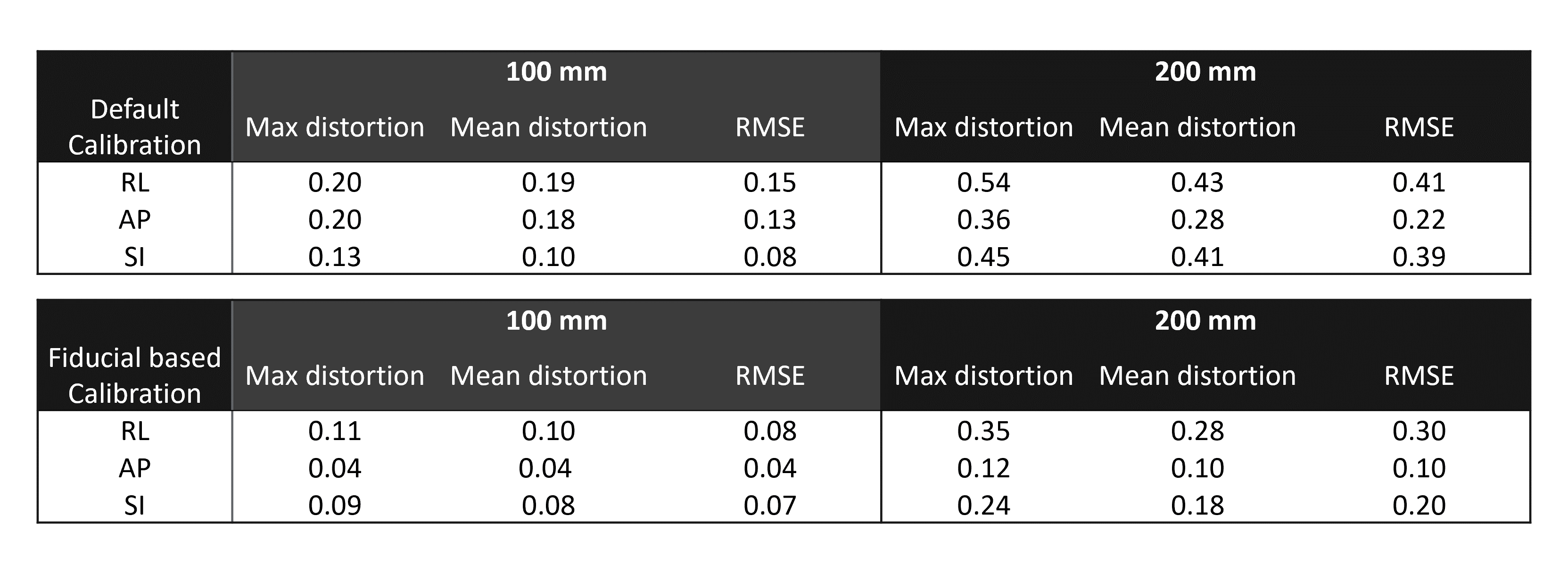
Phantom fiducial displacement with and without GNL correction is shown in Figure 2. It was noted that using default systems calibrations alone was not sufficient to account for the complex non-linear fields, with residual distortion fields exhibiting linear spatial dependence on all three axes. Calibration of the gradients, by minimization of residuals, captured this first-order spatial distortion, highlighting that the linear scaling coefficients can be accurately estimated (Figure 2c).Table1. shows the mean and maximum distortions and RMSE at a 10-cm and 20-cm DSV, with the systems default calibration (residual RMSE ≤0.41 mm), and fiducial-based calibration (residual RMSE ≤0.3 mm). The residuals after additional calibration demonstrated spatial accuracy in line with conventional whole-body gradients11 (~0.08 mT/m/A) and with the asymmetric compact 3T gradient coil8 (0.13 mT/m/A), which has lower amplitude efficiency than MAGNUS due to the proximity of its primary and shield layers. The max-distortion values satisfy QC criteria established in the ADNI study.
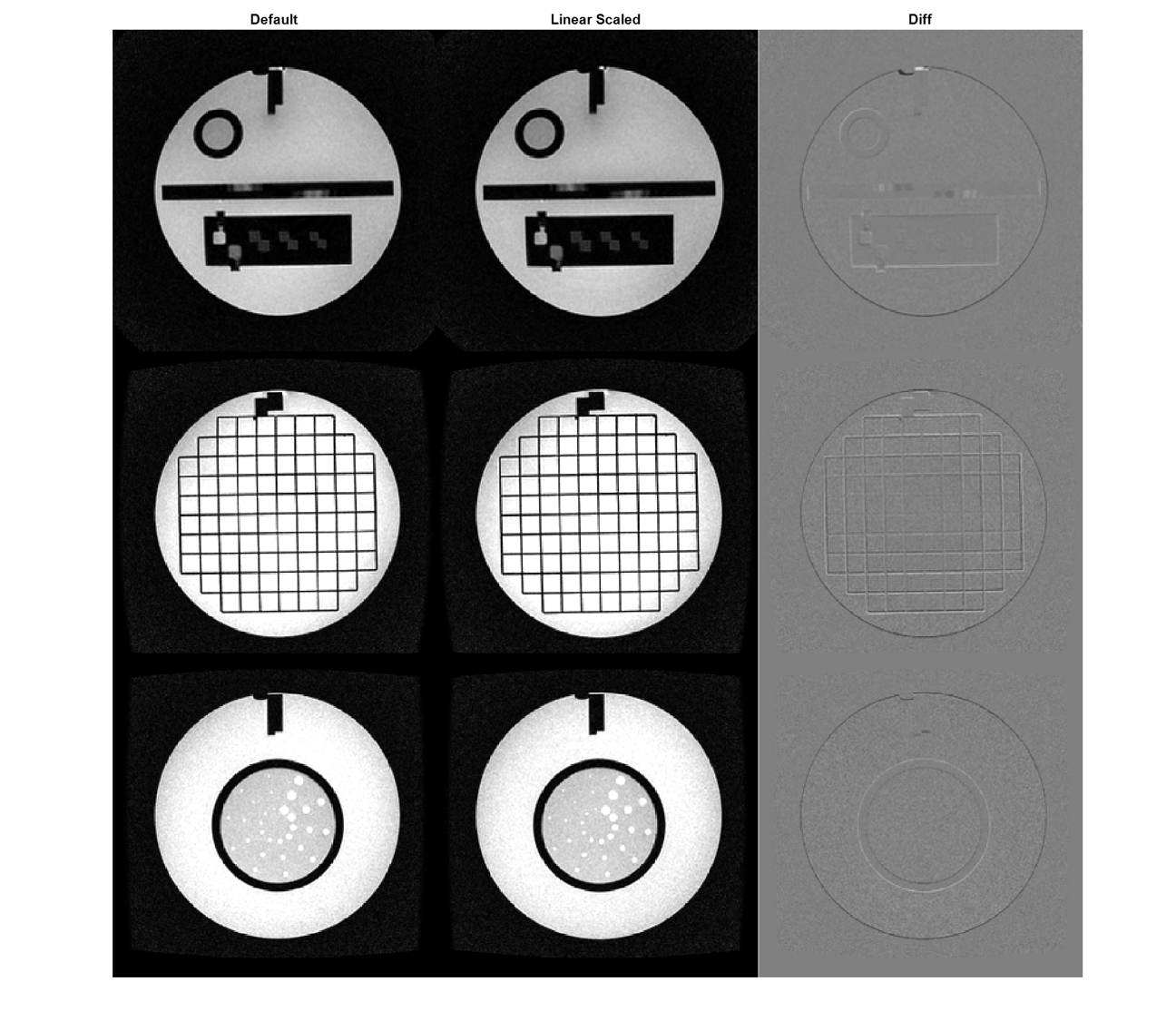
Data from the ACR phantom pre- and post-calibration highlighted marginal improvements in sharpening of contrast at the edges and at grid junctions. Preliminary work with the fiducial phantom and the MAGNUS gradient coil focused on refining linear scaling gradient coefficients. For additional accuracy, simulated spatial distortion coefficients can also be evaluated on a per-system basis using an iterative approach as previously proposed by Tao, et al.8, by inclusion of higher azimuthal orders, or by utilizing a pixel-by-pixel fit over the distortion field13,14
Conclusion
In this work, we demonstrated that geometrical distortions due to GNL can be improved by more precise gradient calibration with a fiducial-phantom in line with the published QC criteria. While this was established on an asymmetric head-only gradient with more complex non-linear fields, a similar method can be utilized for whole-body configurations that have similar high-efficiency. Additionally fiducial-based characterization can potentially identify system specific errors outside of manufacturing and assembly tolerances.Acknowledgements
Grant funding from NIH U01EB028976, NIH U01EB024450, CDMRP W81XWH-16-2-0054.References
1. Alsop, D. C. & Connick, T. J. Optimization of torque-balanced asymmetric head gradient coils. Magnetic Resonance in Medicine 35, 875–886 (1996).
2. Doty, F. D. MRI Gradient Coil Optimization. in Spatially Resolved Magnetic Resonance 647–674 (John Wiley & Sons, Ltd, 1998). doi:10.1002/9783527611843.ch60.
3. Foo, T. K. F. et al. Lightweight, compact, and high-performance 3T MR system for imaging the brain and extremities. Magnetic Resonance in Medicine 80, 2232–2245 (2018).
4. Foo, T. K. F. et al. Highly efficient head-only magnetic field insert gradient coil for achieving simultaneous high gradient amplitude and slew rate at 3.0T (MAGNUS) for brain microstructure imaging. Magnetic Resonance in Medicine 83, 2356–2369 (2020).
5. Myers, C. & Roemer, P. B. Highly linear asymmetric transverse gradient coil design for head imaging. in Proceedings of 10th Annual Meeting SMRM (1991).
6. Huang, S. Y. et al. Connectome 2.0: Developing the next-generation ultra-high gradient strength human MRI scanner for bridging studies of the micro-, meso- and macro-connectome. Neuroimage 243, 118530 (2021).
7. Feinberg, D. A. et al. Design and Development of a Next-Generation 7T human brain scanner with high-performance gradient coil and dense RF arrays. Proceedings of the 29th Annual Meeting of the ISMRM, Virtual Meeting (2021) (2021).
8. Tao, S. et al. Gradient nonlinearity calibration and correction for a compact, asymmetric magnetic resonance imaging gradient system. Phys Med Biol 62, N18–N31 (2017).
9. Tao, A. T. et al. Improving apparent diffusion coefficient accuracy on a compact 3T MRI scanner using gradient nonlinearity correction. J Magn Reson Imaging 48, 1498–1507 (2018).
10. Ching, C. R. K. et al. Phantom-based MRI corrections and power to track brain change. in 2012 9th IEEE International Symposium on Biomedical Imaging (ISBI) 1172–1175 (2012). doi:10.1109/ISBI.2012.6235769.
11. Gunter, J. L. et al. Measurement of MRI scanner performance with the ADNI phantom: Measurement ADNI phantom. Med. Phys. 36, 2193–2205 (2009).
12. Jack, C. R. et al. The Alzheimer’s Disease Neuroimaging Initiative (ADNI): MRI Methods. J Magn Reson Imaging 27, 685–691 (2008).
13. Weavers, P. T. et al. Image-based gradient non-linearity characterization to determine higher-order spherical harmonic coefficients for improved spatial position accuracy in magnetic resonance imaging. Magn Reson Imaging 38, 54–62 (2017).
14. Tao, S., Trzasko, J. D., Shu, Y., Huston, J. & Bernstein, M. A. Integrated Image Reconstruction and Gradient Nonlinearity Correction. Magn Reson Med 74, 1019–1031 (2015).
Figures