5205
Spatial Distortion from Leksell G-frame for Stereotactic Neurosurgery at 1.5T and 3T
Kiran K Seunarine1, Martin M Tisdall2, and Enrico De Vita1
1Physics Group, Department of Radiology, Great Ormond Street Hospital NHS Foundation Trust, London, United Kingdom, 2Department of Neurosurgery, Great Ormond Street Hospital NHS Foundation Trust, London, United Kingdom
1Physics Group, Department of Radiology, Great Ormond Street Hospital NHS Foundation Trust, London, United Kingdom, 2Department of Neurosurgery, Great Ormond Street Hospital NHS Foundation Trust, London, United Kingdom
Synopsis
Keywords: Epilepsy, Precision & Accuracy, Stereotactic
Stereo electroencephalography (sEEG) is a valuable tool for localising seizure-onset zones in focal epilepsy. Pre-surgical planning typically combines CT images, which have little spatial distortion, with MRI images, which have improved cerebral tissue contrast. However, the use of CT results in a potentially unnecessary radiation dose to the patient and additional demand on radiology services. In this work, we assess the additional distortion caused by the stereotactic Leksell G-frame in a single healthy volunteer at both 1.5T and 3T. We show that distortion is <1mm in 99.6% of the brain volume at 3T.Introduction
In stereo electroencephalography (sEEG), depth electrodes are implanted into the brain1. CT is commonly used to image the head once the stereotaxic frame is in place to minimise distortion. However, using MRI-only approach would remove the exposure to ionising radiation, simplify workflows, and reduce the number of scan sessions required.Adoption of robotic-assisted electrode placement in sEEG has resulted in increased accuracy compared to optical frameless navigated placement and a reduced margin of safety around blood vessels2. This improved accuracy is squandered if the imaging suffers from excessive distortion caused by susceptibility/B0 and eddy-current effects from the frame.
Whilst it is expected that geometric inaccuracies would be greater at higher fields, there are situations where it is more practical to use a 3T scanner or lower field scanners are not available. However, there is still no consensus on the suitability of 3T imaging. Theocharis et al3, evaluating MRI-related distortion for radiotherapy planning, suggested that distortion at 3T may be non-negligible but acceptable <5cm from the MRI isocentre. In contrast, other studies have found the level of distortion due to the presence of the G-frame to be unacceptably high at 3T4,5.
Here, we assess the distortion caused by the titanium Leksell G-frame. We scan a healthy volunteer with the G-frame and MR indicator box in place and compare the images to those acquired without the frame to assess the additional distortion the frame causes. We repeat the experiment at 1.5T and 3T.
Methods
Image AcquisitionData were acquired on both a Siemens 3T Vida and Siemens 1.5T Avanto using a Tx/Rx head coil. 3D-T1-weighted MPRAGE acquisitions were performed with the following parameters:
3T: TR/TI/TE=2000/909/3.41ms, isotropic 1mm resolution, 256 partitions, 8° flip-angle, no acceleration, acquisition time 5:31, bandwidth 199Hz/Px.
1.5T: as above except TR/TI/TE=2400/1000/3.71ms, 224 partitions, acquisition time 8:06, bandwidth 180Hz/Px
Following informed consent one participant was scanned with a G-frame, indicator box and G-frame holder (Figure 1 and 2). In the posterior part of the G-frame, titanium pins were inserted upside down, so that the flat back of the pins touched close to back of the skull, separated by laminated card. The front pins were positioned with pointed tips resting just above the participant’s brow, separated by 2 strips of paper tape. The acquisition was repeated without the G-frame, frame holder or indicator box to obtain “reference” images, which should have minimal distortion after the application of the manufacturer distortion correction.
Processing
Images were first bias corrected using SPM12 (https://www.fil.ion.ucl.ac.uk/spm/software/spm12/).
Images acquired with the G-frame and indicator box were registered to their corresponding reference images using a rigid transform followed by a nonlinear registration in niftyreg (http://cmictig.cs.ucl.ac.uk/wiki/index.php/NiftyReg). Displacement maps were generated from the nonlinear component of the registration and the magnitude of the displacements calculated. Following brain extraction (FSL Brain Extraction Tool; https://fsl.fmrib.ox.ac.uk/fsl) histograms of the displacements within the brain were assessed (maximum, peak, median, mean, and standard deviation).
Results
The greatest displacements were observed next to the frame and pins (Figure 3). Maximum displacement magnitudes within the brain (Figure 4) were greater at 3T than 1.5T (1.68 vs 1.20mm). The mean and median distortion were lower at 3T (0.40 ± 0.17mm vs 0.46 ± 0.16mm and 0.45mm vs 0.39mm respectively). The histogram peak occurred at displacements of 0.38mm (3T) and 0.45mm (1.5T).| Field Strength | Histogram Peak (mm) | Median Distortion (mm) | Max Distortion (mm) | Mean distortion ± SD (mm) |
| 1.5T | 0.45 | 0.45 | 1.20 | 0.46 ± 0.16 |
| 3T | 0.38 | 0.39 | 1.68 | 0.40 ± 0.17 |
Table 1 – displacement observed within the brain volume at 1.5T and 3T
The magnitude of distortion was smaller within the brain, which was far from the frame. The percentage of brain volume with distortion >1mm is 0.36% at 3T and 0.19% at 1.5T. The centre of the thalami (a common target in stereotactic neurosurgery) are approximately 75mm away from the top of the G-frame. In these regions distortion is <1mm at both 3T and 1.5T.
Discussion and conclusion
Images acquired at 3T had a smaller median displacement within the brain volume than at 1.5T (0.39mm compared to 0.45mm at 1.5T). However, there was a greater maximum displacement within the brain volume at 3T than at 1.5T (1.68mm at 3T vs 1.20mm at 1.5T).As expected, the greatest distortions were near the G-frame and titanium pins. Therefore, distortion may be minimised by positioning the head as superior as possible in the G-frame (within the confines of the indicator box). When targeting structures such as thalamic nuclei, where high accuracy is required, positioning the area of interest central within the G-frame may further help to minimise distortion.
In this work we only assessed distortion with titanium pins, which may cause more severe distortion than other available pins. The use of aluminium or titanium-tipped aluminium pins may further reduce distortion4.
In conclusion, we have shown that the distortion caused by the titanium Leksell frame, while non-negligible, is <1mm in 99.6% of voxels within the brain at 3T, using our specific 3D-T1-weighted sequence. Further work is required to assess the cumulative effect of distortion from other sources as well as the effect of distortion on the MR indicator box, which is used for registration in surgery.
Acknowledgements
No acknowledgement found.References
- De Benedictis, A., Trezza, A., Carai, A., et al (2017), “Robot-assisted procedures in pediatric neurosurgery”, Neurosurgical Focus, 42(5):E7
- Sharma, J.D., Seunarine, K.K., Tahir, M.Z., Tisdall, M.M. (2019), “Accuracy of robot-assisted versus optical frameless navigated stereoelectroencephalography electrode placement in children”, Journal of Neurosurgery, 23(3):297-302
- Theocharis, S., Pappas, E.P., Seimenis, I., et al (2022), “Geometric distortion assessment in 3T MR images used for treatment planning in cranial Stereotactic Radiosurgery and Radiotherapy”, PLos ONE, 17(5): e0268925
- Nakazawa, H., Mori, Y., Yamamuro, O., et al (2014), “Geometric accuracy of 3D coordinates of the Leksell stereotactic skull frame in 1.5 Tesla- and 3.0 Tesla-magnetic resonance imaging: a comparison of three different fixation screw materials”, Journal of Radiation Research, 55: 1184-1191
- Poulen, G, Seng, E.C., De Champfleur, N.M., et al (2020), “Comparison between 1.5- and 3-T Magnetic Resonance Acquisitions for Direct Targeting Stereotactic Procedures for Deep Brain Stimulation: A Phantom Study” Stereotactic and Functional Neurosurgery, 98:337-344
Figures
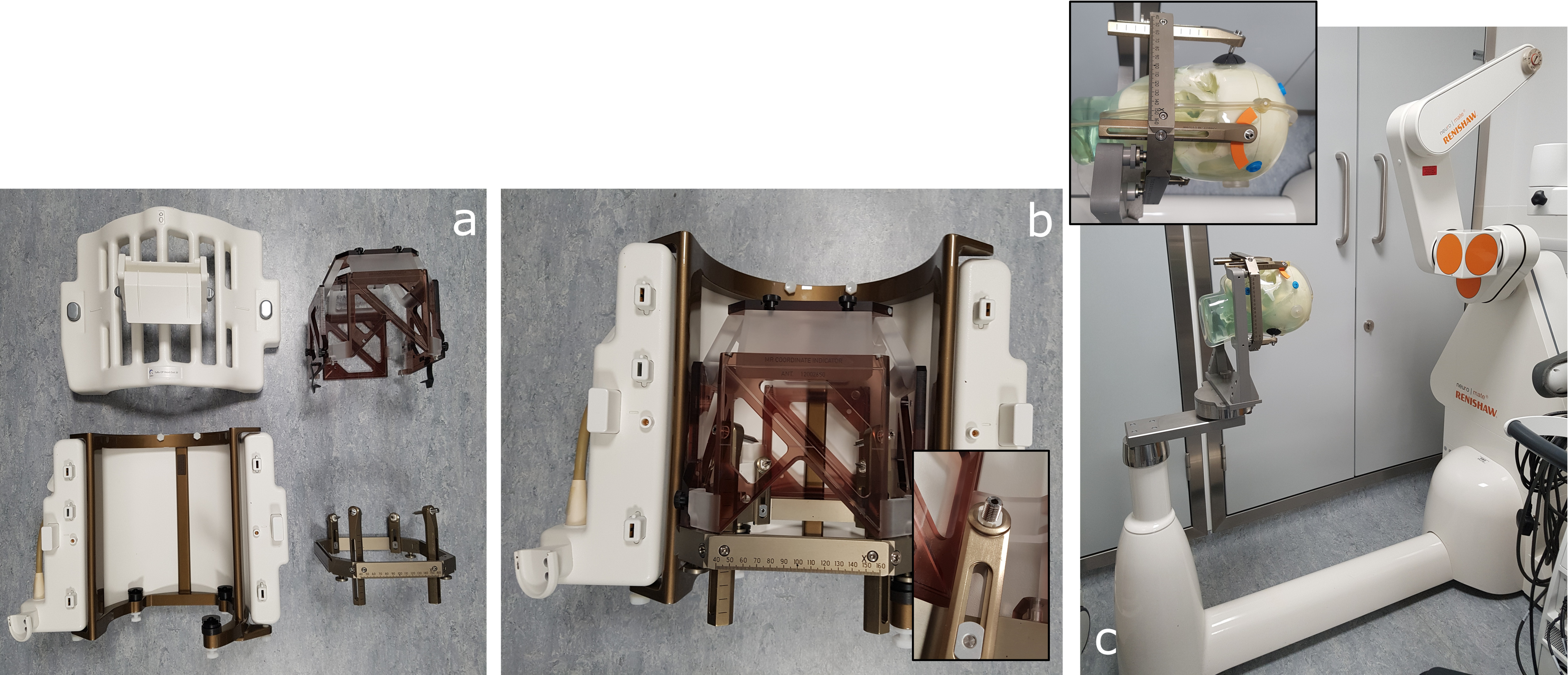
Figure 1 - a) The Leksell titanium G-frame (bottom right), MR Indicator box (top right) and TxRx coil with its frame holder (bottom left), b) here the MR indicator box has been clipped onto the G-frame and the assembly locked into the frame holder, which is secured to the posterior part of the Tx-Rx coil (inset: rear pins reversed for safety), and c) The G-frame attached to the Renishaw robot, which provides accurate positioning of drill bits and other tools for sEEG electrode and DBS insertion.
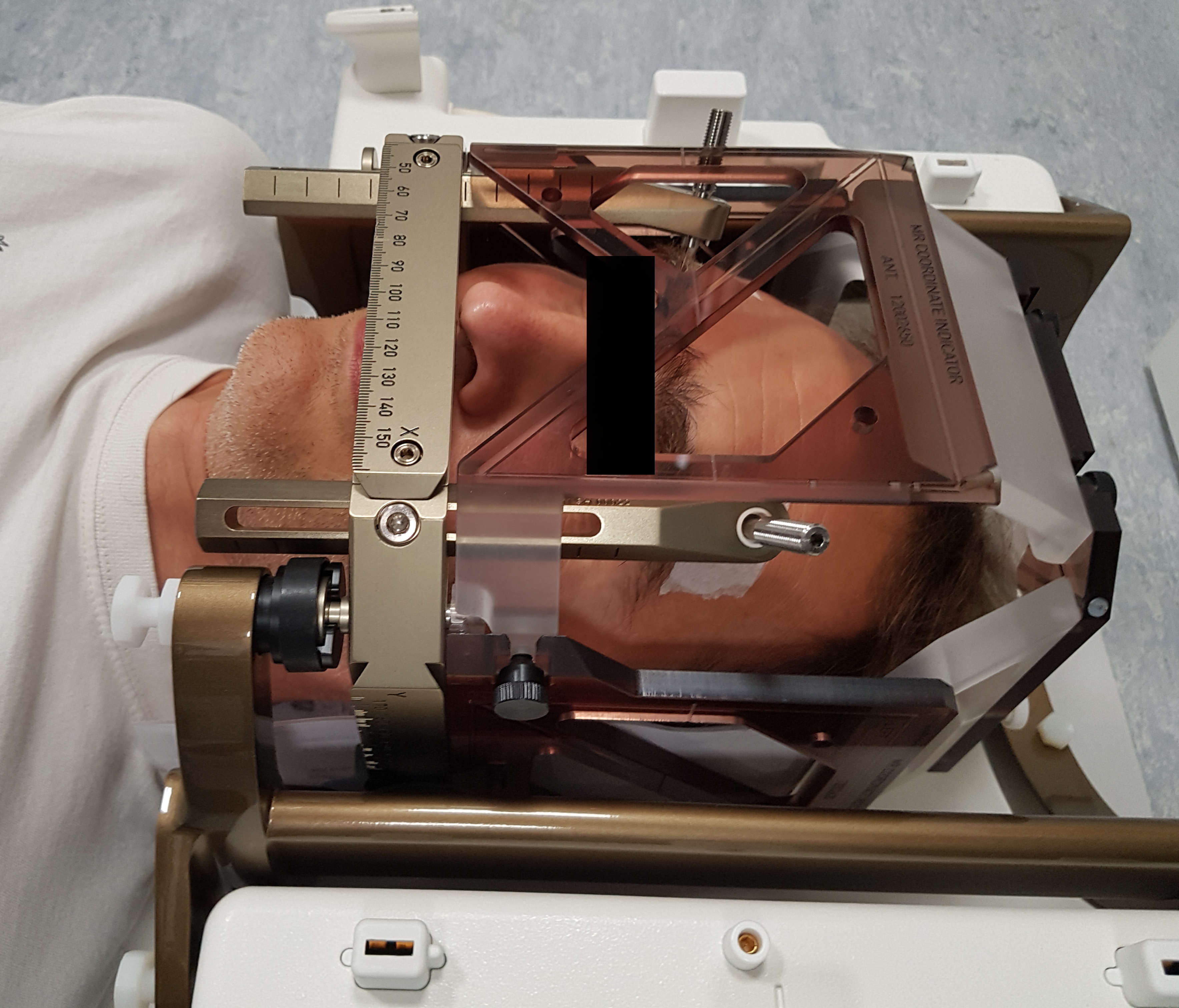
Figure 2 - Photograph of the volunteer ‘pinned’ within the Leksell G-frame with the MR-indicator box clipped in place, within the posterior part of the TxRx head coil. NB. The geometry of the TxRx coil is exactly the same for 3T and 1.5T.
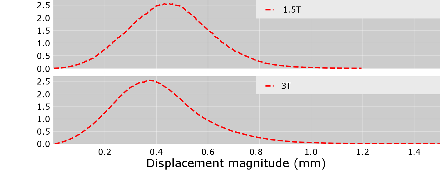
Figure 3 - Histograms of displacement magnitude with brain volume at 1.5T (top) and 3T (bottom)
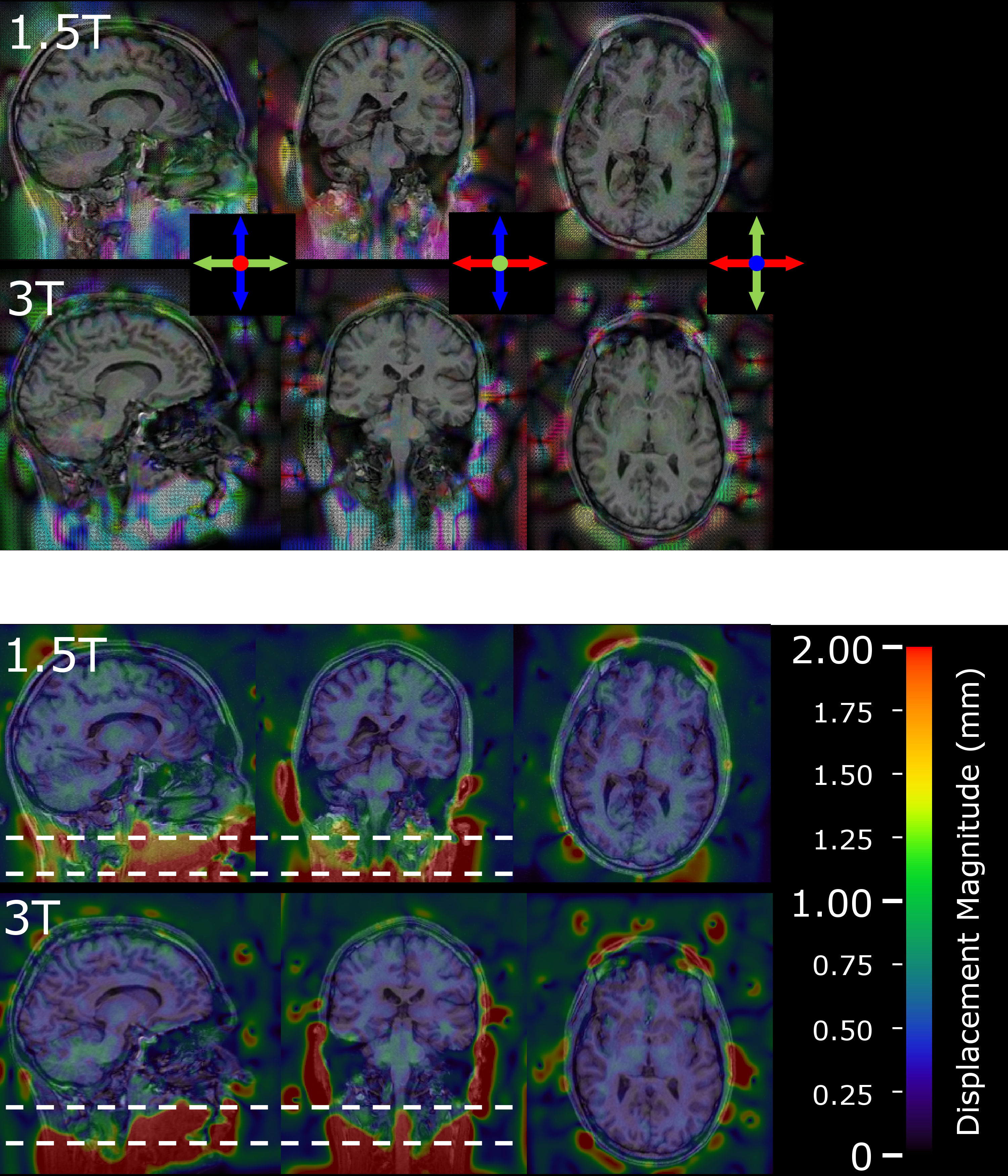
Figure 4 - Displacements required to register image acquired with the Leksell frame and indicator box to reference image at 1.5T and 3T. Upper two rows show direction of displacement (red – left/right, green - anterior/posterior, blue superior/inferior); the lower two rows show the magnitude of displacement. The position of the G-frame is indicated by the dashed lines.
DOI: https://doi.org/10.58530/2023/5205