5097
Validation of the Single Reference Variable Flip Angle T1 mapping method in an innovative phantom1Biomedical Engineering, University of Utah, Salt Lake City, UT, United States, 2Radiology and Imaging Sciences, University of Utah, Salt Lake City, UT, United States
Synopsis
Keywords: Quantitative Imaging, Quantitative Imaging, T1 mapping
An innovative cylindrical phantom is used to mimic a dynamic acquisition with temperature-induced changes in T1. Single reference (SR) variable flip angle (VFA) T1 maps are acquired at several rotational positions of this phantom, and are compared to corresponding T1 values acquired with the dual-angle variable flip angle and inversion recovery T1 mapping methods. The SR-VFA method of T1 mapping is shown to produce T1 accuracy within 4-10% of both inversion recovery and dual-angle VFA T1 measurements.Introduction
The rise of MR-guided focused ultrasound ablative surgeries has led to an increased need for fast, accurate temperature mapping in all tissues, including in tissues such as fat and bone, whose temperature change cannot be measured with standard proton resonance frequency shift (PRFS) thermometry. Quantitative T1-based thermometry has emerged as a potential solution to this problem. Recently, a technique called the single-reference (SR) variable flip angle (VFA) method1 of T1 mapping was developed as a way to produce one T1 map per dynamic image, thereby potentially matching the temporal resolution of PRFS thermometry. However, this method has not been rigorously compared to the clinically accepted VFA method, nor to the gold standard T1 mapping method, inversion recovery. This work aims to validate the SR-VFA T1 mapping method against the gold standard inversion recovery method using an innovative phantom to mimic the dynamic processes of temperature-induced T1 change.Methods
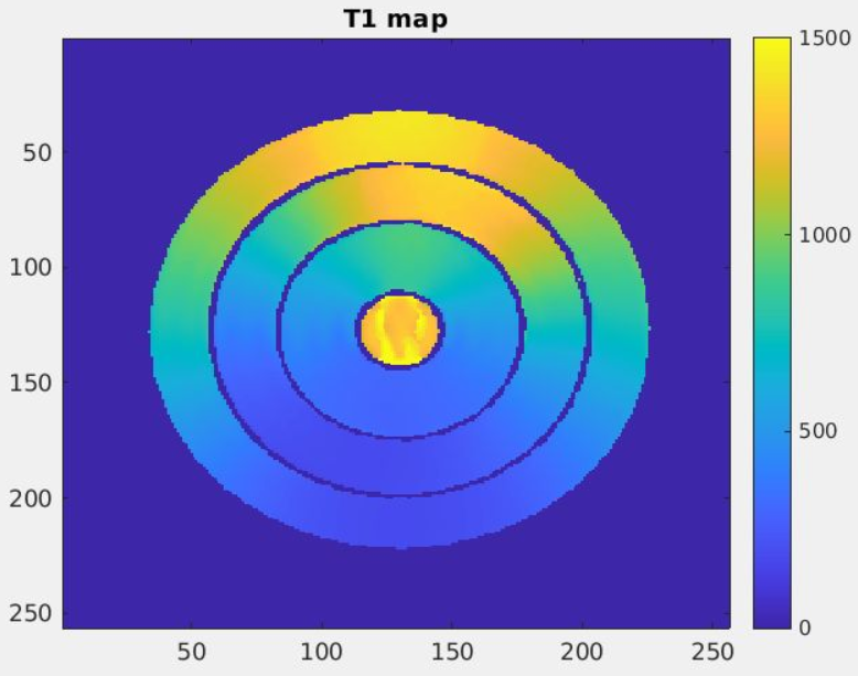
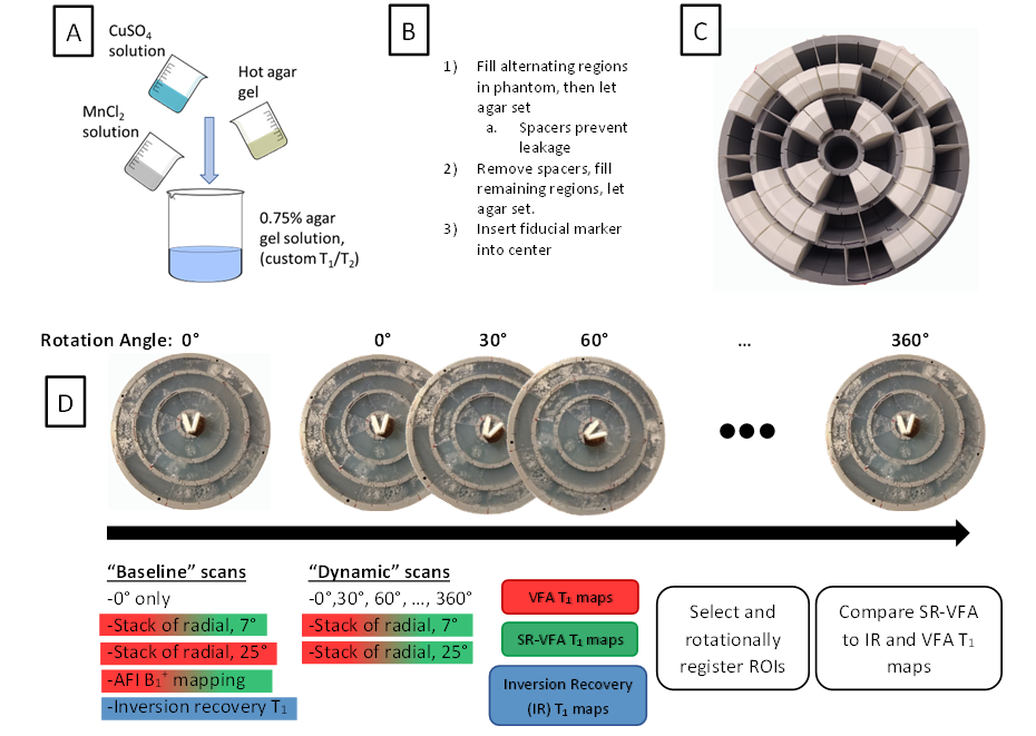
An innovative cylindrical phantom was developed with three concentric rings, each of which was filled with 0.75% agar solution with varying MnCl2 and CuSO4 concentrations2,3 so as to produce T1 values varying smoothly in the range of ~200 to 2500 ms (see Figure 1), and T2 values of ~20 ms to 250 ms. The phantom was centered on a rotating stand, and single-slice turbo-spin-echo inversion recovery measurements were taken at inversion times of 25, 75, 150, 400, 900, 1500, and 3500 ms. Following these measurements, 3D variable flip angle (VFA) stack-of-stars measurements (TR = 20 ms, TE = 1.24 ms) were taken with two scans at flip angles of 7° and 25°, with the center of the slab at the same location as the 2D inversion recovery slice. 3D B1+ mapping with the AFI method4 was performed with a flip angle of 60° and TR2/TR1 = 150 ms / 30 ms. Following these initial “baseline” measurements, the phantom was manually rotated by 30° from 0° to 360°, and the VFA measurements were repeated after each rotation.Images were reconstructed offline via in-house MATLAB (Mathworks, Natick, MA) code. Inversion recovery T1 measurements were created using the reduced dimension nonlinear least squares fit method5. Other T1 maps were reconstructed with the VFA and SR-VFA methods, with B1+ correction from the B1+ map acquired at 0° rotation. For the single reference method, the high flip angle scans at each incremental rotation of the phantom served as the “dynamic” images, whereas the two scans at 0° rotation served as the “baseline” images.
Following T1 map creation, a 3x3 median filter was applied, and 120 evenly spaced 3-voxel-radius circular regions of interest (ROIs) were selected circularly along each of the three concentric rings for a central slice of the SR-VFA T1 map at each of the 13 rotational points. These were registered with corresponding ROIs in the inversion recovery T1 maps and VFA T1 maps for comparison. Figure 2 gives a visual description of these methods.
Results
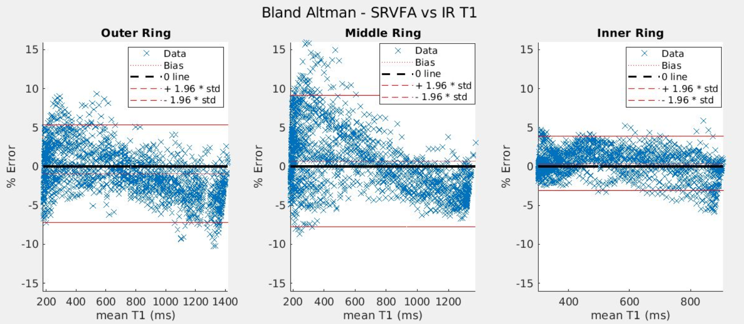
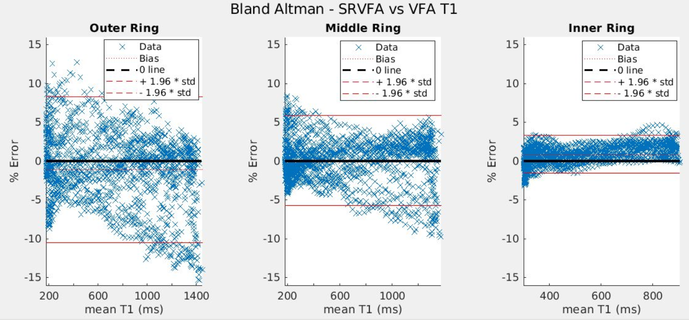
Figure 3 gives a Bland Altman plot of the difference in T1 values between SR-VFA and the inversion recovery method as a function of the mean T1 value. The SR-VFA T1 values from small ROIs were within ±4-10% of the corresponding inversion recovery T1 values. Similar results were obtained with the comparison between the SR-VFA and VFA T1 mapping methods, as shown in Figure 4. Notably, in both method comparisons, the outer ring and inner ring exhibited the largest and smallest offset respectively in both method comparisons. The largest ring and smallest ring also correspond with the largest (200-1400 ms) and smallest (300-900 ms) “dynamic” range of T1s from one end of the rotated phantom to another.Discussion
This work shows that the single-reference variable flip angle (SR-VFA) method of T1 mapping provides comparable accuracy to the VFA method. For this to happen, a sufficiently low TE must be attained such that TE << T2*.1 Otherwise, some estimate of dynamic T2* changes must be attained, such as through multi-echo acquisition.6 Notably, as discussed by Malmberg et al. in 2022, the SR-VFA method tends to be more accurate for smaller changes in T1 relative to baseline6. Thus, we would expect that the SR-VFA method’s accuracy would be better for the inner ring than the outer ring due to the smaller dynamic T1 range. This is confirmed experimentally with Figures 3 and 4. Further, errors in B1+ mapping, especially in the outside ring where B1+ uniformity would be the worst, could account for some of the errors in T1 .Future work will evaluate a true dynamic comparison of the SR-VFA method to the gold standard via a rotating platform powered by an MRI-compatible servo motor,7 and also seek to perform T1 validation in-vivo.
Conclusion
The single reference variable flip angle T1 mapping method is shown to be a valid, faster substitute for the VFA method in low TE acquisitions in phantoms. This work is a key step towards clinical use of faster T1 mapping in combined PRF/T1 thermometry for focused ultrasound ablative surgeries, as well as dynamic contrast-enhanced imaging.Acknowledgements
This research was made possible thanks to the Mark H. Huntsman endowed chair, and NIH grants R01EB028316, R37CA224141, and R03EB029204.References
1Svedin BT, Payne A, Parker DL. Simultaneous proton resonance frequency shift thermometry and T1 measurements using a single reference variable flip angle T1 method. Magnetic Resonance in Medicine. 2019;81(5):3138-3152. doi:10.1002/mrm.27643
2Thangavel K, Saritaş EÜ. Aqueous paramagnetic solutions for MRI phantoms at 3 T: A detailed study on relaxivities. Turk J Elec Eng & Comp Sci. 2017;25(3):2108-2121.
3Gopalan K, Tamir JI, Arias AC, Lustig M. Quantitative anatomy mimicking slice phantoms. Magn Reson Med. 2021;86(2):1159-1166. doi:10.1002/mrm.28740
4Yarnykh VL. Actual flip-angle imaging in the pulsed steady state: A method for rapid three-dimensional mapping of the transmitted radiofrequency field. Magnetic Resonance in Medicine. 2007;57(1):192-200. doi:10.1002/mrm.21120
5Barral JK, Gudmundson E, Stikov N, Etezadi-Amoli M, Stoica P, Nishimura DG. A robust methodology for in vivo T1 mapping. Magnetic Resonance in Medicine. 2010;64(4):1057-1067. doi:10.1002/mrm.22497
6Malmberg MA, Odéen H, Parker DL. Effects of T2* on accuracy and precision of dynamic T1 measurements using the single reference variable flip angle method: a simulation study. Medical Physics. n/a(n/a). doi:10.1002/mp.15476
7Hofstetter LW, Hadley R, Merrill R, Pham H, Fine GC, Parker DL. MRI-compatible electromagnetic servomotors for image-guided robotic procedures. arXiv:210812266 [physics]. Published online August 16, 2021. Accessed April 28, 2022. http://arxiv.org/abs/2108.12266
Figures