5081
High-density dipole array for human lumbar spine cord imaging at 7T
Ming Lu1, Shuyang Chai2,3, and Xinqiang Yan2,3
1College of Nuclear Equipment and Nuclear Engineering, Yantai University, Yantai, China, 2Vanderbilt University Institute of Imaging Science, Vanderbilt University Medical Center, Nashville, TN, United States, 3Department of Radiology and Radiological Sciences, Vanderbilt University Medical Center, Nashville, TN, United States
1College of Nuclear Equipment and Nuclear Engineering, Yantai University, Yantai, China, 2Vanderbilt University Institute of Imaging Science, Vanderbilt University Medical Center, Nashville, TN, United States, 3Department of Radiology and Radiological Sciences, Vanderbilt University Medical Center, Nashville, TN, United States
Synopsis
Keywords: RF Arrays & Systems, High-Field MRI
The Dipole antenna, which has a long longitudinal coverage and deep penetration, has demonstrated a better transmit efficiency for spinal cord imaging compared to the standard loop coil. However, owing to the inevitable coupling, the number of dipoles is highly limited. In this work, we find that the number of dipoles could be doubled if they are be shortened in different ways and arranged to interleave. An 8-channel dipole array consisting of 4 inductor-shortened dipoles and 4 folded dipoles was designed and numerically investigated for 7T lumbar spinal cord imaging.Introduction:
Ultra-high field MRI provides significant benefits for human spinal cord imaging in terms of high signal-to-noise ratio and high spatial resolution [1]. The dipole antenna, which has a long longitudinal coverage and deep penetration, has demonstrated a better transmit efficiency for spinal cord imaging compared to the standard loop coil [2]. However, owing to the inevitable coupling [3], the number of dipoles is highly limited. In this work, we find that the number of dipoles could be doubled if neighbor elements are shortened in different ways. An 8-channel dipole array consisting of 4 inductor-shortened dipoles and 4 folded dipoles was designed and numerically investigated for 7T lumbar spinal cord imaging.Method:
There are two typical ways to shorten the half-wavelength dipole antenna to match the imaging area. One way is to shorten the dipole electrically with distributed [4] or lumped inductors [5], as shown in Figure 1A. Figure 1C and 1D show how the coupling between two inductor-shortened dipole antennas (length 21 cm, conductor width 6.35 mm) changes with respect to their separation distance. The mutual coupling between the two inductor-shortened dipoles increases as their distance decreases. The closest distance that can keep a good decoupling performance is 7 cm (Figure 1D), which is also consistent with previous works [2]. 7 cm, therefore, defines the closest distance between identical dipoles. The other is to fold the dipole vertically [6], as shown in Figure 1B. For the folded dipole, the height and gap would affect its field distribution and thereby its crosstalk with others. In this work, we varied the height from 3 to 5 cm (in steps of 0.5 cm) and the gap from 2 to 10 cm (in steps of 1 cm) to investigate how the coupling with an adjacent folded dipole (7 cm apart, Figure 1E) and the coupling with an adjacent inductor-shortened dipole (3.5 cm apart, Figure 1F) change. This investigation was performed in full-wave electromagnetic (EM) simulation using Ansys HFSS. For all scenarios, a body-shaped phantom (σ = 0.6 S/m and ξr = 78) was placed 1 cm below the coils as the loading.Then an 8-channel high-density mixed dipole array (4 inductor-shortened dipoles and 4 folded dipoles) was designed for lumbar spinal cord imaging at 7T, with the height and gap of folded dipoles chosen to be optimal values of 3 cm and 10 cm. Normalized SNR and g-factor were calculated using all 8 dipoles and compared to those using 4 inductor-shortened dipoles and 4 folded dipoles.
Results:
The coupling between two 7-cm-apart folded dipoles increases as the gap decreases and as the height increases, as shown in Figure 2A. On contrary, the coupling between 3.5-cm-apart inductor-shortened and folded dipoles decreases as the gap decreases and as the height increases (Figure 2B). Therefore, the gap and height of folded dipoles should be chosen with the consideration of both kinds of coupling. Figure 3 plots the central axial B1- efficiency map of a folded dipole with different heights and gaps. The folded dipole with a height of 3 cm and a gap of 10 cm exhibits the highest B1- efficiency at the region of interest and thereby was chosen for the 8-channel design.Figure 4B shows the simulated S-parameter plots of the 8-channel dipole array. Note that these dipoles are highly packed which cannot be realized by any existing method. The average decoupling between two adjacent inductor-shortened dipoles (skip one folded dipole) and between two adjacent folded dipoles (skip one inductor-shortened dipole) is -16.1 and -16.4 dB, respectively. The average decoupling between adjacent mixed dipoles is -12 dB. The worst decoupling is approximately -11 dB (dipoles 1 and 2 in Figure 4A). Figure 5 compared the simulated SNR using all 8 dipoles and 4 dipoles. Simulation results reveal that the 8-ch dipole array has a surface/deep SNR gain of 92%/19% over the 4-ch inductor-shorten dipole array and a gain of 55%/27% over the 4-ch folded dipole array.
Conclusion:
We propose a novel 8-channel high-density dipole array for 7T lumbar spinal cord imaging, in which the interleave dipoles are shortened in different ways. This simple design enables a double number of dipole antennas and can significantly enhance the SNR in the deep area as well as surface area.Acknowledgements
This work was supported by NIH R01 EB 031078. This work was performed during the period of Dr. Ming Lu’s visit to Vanderbilt University Institute of Imaging Science.References
- Barry R L, Vannesjo S J, By S, et al. Spinal cord MRI at 7T. Neuroimage, 2018, 168: 437-451.
- Duan Q, Nair G, Gudino N, et al. A 7T spine array based on electric dipole transmitters. Magnetic resonance in medicine, 2015, 74(4): 1189-1197.
- Yan X, Zhang X, Wei L, et al. Design and test of magnetic wall decoupling for dipole transmit/receive array for MR imaging at the ultrahigh field of 7T. Applied magnetic resonance, 2015, 46(1): 59-66.
- Raaijmakers A J E, Italiaander M, Voogt I J, et al. The fractionated dipole antenna: A new antenna for body imaging at 7 Tesla. Magnetic resonance in medicine, 2016, 75(3): 1366-1374.
- Wiggins G C, Zhang B, Lattanzi R, et al. The electric dipole array: an attempt to match the ideal current pattern for central SNR at 7 Tesla, Proceedings of the 20th Annual Meeting of ISMRM, Melbourne, Australia. 2012, 20: 541.
- Avdievitch N, Solomakha G, Ruhm L, et al. Decoupling of folded dipole antenna elements of a human head array at 9.4 T. 2020: 464..
Figures
Figure
1. A and B: Circuit diagrams of inductor-shortened dipole (A) and folded dipole
(B). C, E and F: Simulation models of a pair of inductor-shortened dipoles (C),
folded dipoles (E) and mixed dipoles (F). D: S21 parameter between two
inductor-shortened dipole antennas changes with respect to their separation distance.
Figure
2. A: Simulated decoupling performance between two folded dipoles (7 cm apart)
with different geometrical parameters in the folded dipoles. B: Simulated decoupling performance between a
folded dipole and an inductor-shortened (3.5 cm apart) with different
geometrical parameters in the folded dipoles.
Figure
3. B1- efficiency of a folded dipole with various heights and gaps. The folded
dipole with a height of 3 cm and a gap of 10 cm exhibts the strongest B1-
efficiency in the region of interest.
Figure
4. A: simulation model of the 8-channel high-density dipole array on a
body-shaped phantom. B: S-parameter plots of 8-channel high-density dipole
array. All elements were well tuned to 298 MHz and matched to 50 Ω, with return
loss less than - 30 dB.
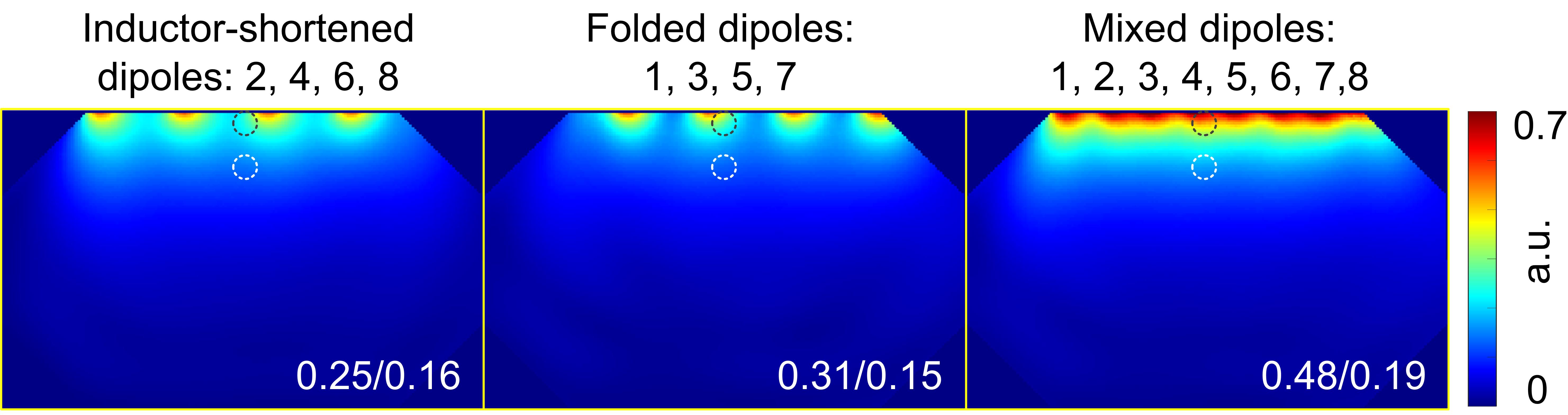
Figure
5. Simulated normalized SNR maps in the
central axial slice of the phantom using 4 inductor-shortened dipoles (dipoles
2,4,6,8 in Figure 4A), 4 folded dipoles (dipoles 1, 3, 5, 7 in Figure 4A) and
all 8 dipoles (from left to right).
DOI: https://doi.org/10.58530/2023/5081