5080
A 16-Channel Proton/Sodium Transmit/Receive Array Design for 7 Tesla Head Imaging
Menglu Wu1,2, Jérémie Clément1,3, Jules Vliem1,4, David Leitão 1, Raphael Tomi-Tricot1,2,5, and Özlem Ipek1,2
1Biomedical Engineering, King's College London, London, United Kingdom, 2London Collaborative Ultra high field System (LoCUS), King's College London, London, United Kingdom, 3System Technologies, Siemens Healthcare GmbH, Erlangen, Germany, 4Electrical Engineering, Technical University of Eindhoven, Eindhoven, Netherlands, 5MR Research Collaborations, Siemens Healthineers, Frimley, United Kingdom
1Biomedical Engineering, King's College London, London, United Kingdom, 2London Collaborative Ultra high field System (LoCUS), King's College London, London, United Kingdom, 3System Technologies, Siemens Healthcare GmbH, Erlangen, Germany, 4Electrical Engineering, Technical University of Eindhoven, Eindhoven, Netherlands, 5MR Research Collaborations, Siemens Healthineers, Frimley, United Kingdom
Synopsis
Keywords: RF Arrays & Systems, Non-Proton
7T MRI has great potential to enhance the sensitivity to 23Na, allowing access to functional and anatomical information when combined with proton imaging. We introduce an RF coil design of a 16-channel Tx/Rx head array composed of eight proton dipoles and eight overlapping sodium loops for 7T. The initial results were acquired on phantoms with comparable performance for both nuclei, and a 40% B1+ gain was reported in sodium channels against the commercial coil. All elements were well-decoupled (-7.2dB to -36dB) without implementation of multiple layers or RF shield, paving the way for future simultaneous 1H/23Na MRI acquisition at 7T.Introduction
Sodium MRI allows access to functional neurological activities1, but suffers from low SNR due to its intrinsic low sensitivity. Several designs have attempted to combine sodium (23Na) and proton (1H) imaging with multi-layered arrangements2-4. However, complex multi-layered coil array designs lead to increased coupling and therefore SNR losses in both nuclei. At high field there are also challenges in achieving uniform imaging performance due to RF inhomogeneities, particularly for the proton frequency. The aim of this study is to design a single layer 8-channel sodium and 8-channel proton transceiver head array that will address both of these issues at once for improved performance in both nuclei for 7T.Methods
Coil ConstructionA coil array system for both 23Na (78.6MHz) and 1H (297.2MHz) imaging was developed for 7T. The coil consists of eight transmit/receive proton dipoles and eight transmit/receive sodium loops distributed symmetrically around an acrylic cylinder (diameter=30cm) that was supported by custom-designed 3D-printed holders (PLA,Ultimaker). Each proton dipole (170mm×15mm)5 was placed in the centre of each sodium loop (250mm×150mm). Loops were made with copper wire, and tuning/matching was achieved with a combination of fixed capacitors (ATC, NY) and variable capacitors (NMAJ15HV,knowles, IL).(Fig.1a)
In-house built baluns tuned to their respective frequency were integrated along the coaxial cable (K_02252_D,Huber+Suhner,Switzerland) to decouple each element. The proton baluns were fixed on the coil by 3D-printed holders to ensure orthogonal orientation of the cable to the dipole.(Fig.1a) The sodium loop coils were further decoupled by optimising the overlapping distance (~15% of loop width) between neighbouring channels. To minimise coupling between sodium and proton components, four LC traps and an additional balun at proton frequency were implemented in each sodium loop. (Fig.1a,b)
Bench measurements
Bench measurements were carried out with dedicated phantoms for proton and sodium.(Fig.1c,d) The former was a cylindrical phantom (diameter=21cm,length=21cm,0.45w/v NaCl), while the latter was a sphere (diameter=15cm,125mmol NaCl). Central alignment of both phantoms was ensured by a custom-designed 3D-printed holder. Q-factor and S-matrix values were recorded from VNA (E5063A ENA, Keysight) to verify optimised tuning/matching and decoupling prior to MRI acquisitions (Fig.2).
MRI acquisition
MR data were acquired on a single-transmit for sodium and parallel-transmit for proton 7T MR scanner (MAGNETOM Terra, Siemens Healthineers, Erlangen, Germany) with a power splitter and respective TR switches (MR coiltech, UK) for each acquisition. B1+ map for the proton array in the circularly polarised (CP) mode (B1,CP) was assessed with a 3D actual-flip-angle AFI sequence (TR=200ms, 4.4×4.4×4mm3, FA=60deg)6. Signal levels in CP mode (SCP) and individual channels (Sn) were acquired with 3D GRE sequence (TR/TE=10ms/2.48ms, 4×4×4mm3, FA=5deg, bandwidth=250Hz/pixel) using pTx system and setting the amplitude of the channel in question to 0.35 and others to zero in a circular fashion. B1+ maps for individual proton transmit channels were calculated7 with: $$$ B_{1,n} =\frac{S_{n}\cdot B_{1,CP}}{S_{CP}} $$$.
For sodium elements, B1+ maps were calculated with the double-angle method8 with middle axial slices acquired by 2D GRE sequences (TR/TE=150ms/1.92ms, FA=45/90deg, 6.6×6.6x25.0mm3, 32 averages, bandwidth=600Hz/pixel). The 45/90deg combination was verified by comparing signals from repeated measurements of different flip angles. Individual channel results were acquired by manually switching channels on the TR switch and bypassing the power splitter at each measurement. The same calculation was applied to a commercial 32-channel 1H/23Na coil array (Siemens Healthineers/Rapid Biomedical) on its sodium elements as comparison. (Fig.4)
Results
The S-matrix showed satisfying tune-and-match results (Sii:1H:-14 to -20dB;23Na:-15.8 to -27dB).(Fig.2) The decoupling among nuclei was well-achieved (Sij:1H/1H:-8dB to -16dB;23Na/23Na:-7.2dB to -27dB;1H/23Na:-25dB to -36dB). Proton B1+ maps indicated that the in-house built coil generated a circular polarised field with relatively uniform contribution from all channels (Fig.3). VNA measurements indicated a high Q-factor ratio of 330/35 (unloaded/loaded) for a sodium loop located on the array. Individual B1+ transmit field contributions from sodium loops were less uniform, however, an overall 40% B1+ gain was reported compared to the commercial coil in CP mode.(Fig.4)Discussion
The in-house built coil exhibited a robust performance in simultaneous proton and sodium imaging in absence of an RF shield. The presence of the sodium coil does not alter the field efficiency of the proton/sodium coil array as compared to the similar dipole proton array9. Testing with the RF sweeper (Morris Instruments Inc., Canada) indicated ~0.5MHz shift in frequencies of channels 1, 3 and 7 when placed in the isocentre of the scanner. This is likely due to their relative proximity to the bore. Given the high Q-factor of the sodium loops, the homogeneity can be further improved by tuning/matching based on their relative positions. Moreover, SNR could be increased with implementation of multichannel receivers for proton and sodium.Conclusion
In this work, we have shown the initial imaging results on phantoms to characterise a custom-built 8-channel 1H/8-channel 23Na head transceiver array for 7T. The coil showed great potential for high signal in sodium imaging with similar performance in the proton elements to proton-only arrays so that one unified examination will be sufficient, reducing time and labour costs in clinical practice. In-house developed pTx For future work, SARmax of the array will be investigated with electromagnetic simulations to enable simultaneous 1H/23Na imaging for the benefit of patient diagnosis.Acknowledgements
This work was supported by King’s China Scholarship Council, by core funding from the Wellcome/EPSRC Centre for Medical Engineering [WT203148/Z/16/Z], Wellcome Trust Collaboration in Science grant [WT201526/Z/16/Z], and by the National Institute for Health Research (NIHR) Biomedical Research Centre based at Guy’s and St Thomas’ NHS Foundation Trust and King’s College London and/or the NIHR Clinical Research Facility. The views expressed are those of the author(s) and not necessarily those of the NHS, the NIHR or the Department of Health and Social Care.References
1. Boada FE, LaVerde G, Jungreis C, Nemoto E, Tanase C, Hancu I. Loss of Cell Ion Homeostasis and Cell Viability in the Brain: What Sodium MRI Can Tell Us. In: Current Topics in Developmental Biology. Academic Press; 2005 [cited 2022 Nov 8]. p. 77–101. (In Vivo Cellular and Molecular Imaging; vol. 70). Available from: https://www.sciencedirect.com/science/article/pii/S00702153057000412. Shajan G, Mirkes C, Buckenmaier K, Hoffmann J, Pohmann R, Scheffler K. Three-layered radio frequency coil arrangement for sodium MRI of the human brain at 9.4 Tesla. Magn Reson Med. 2016;75(2):906–16.
3. Lakshmanan K, Brown R, Madelin G, Qian Y, Boada F, Wiggins GC. An eight-channel sodium/proton coil for brain MRI at 3 T. NMR Biomed. 2018;31(2):e3867.
4. Brown R, Lakshmanan K, Madelin G, Alon L, Chang G, Sodickson DK, et al. A Flexible Nested Sodium and Proton Coil Array with Wideband Matching for Knee Cartilage MRI at 3 Tesla. Magn Reson Med. 2016 Oct;76(4):1325–34.
5. Clément JD, Gruetter R, Ipek Ö. A human cerebral and cerebellar 8-channel transceive RF dipole coil array at 7T. Magn Reson Med. 2019;81(2):1447–58.
6. Yarnykh VL. Actual flip-angle imaging in the pulsed steady state: a method for rapid three-dimensional mapping of the transmitted radiofrequency field. Magn Reson Med. 2007 Jan;57(1):192–200.
7. de Moortele PFV, Ugurbil K. Very Fast Multi Channel B1 Calibration at High Field in the Small Flip Angle Regime. :1.
8. Bottomley PA, Ouwerkerk R. The Dual-Angle Method for Fast, Sensitive T1 Measurement in Vivo with Low-Angle Adiabatic Pulses. J Magn Reson B. 1994 Jun 1;104(2):159–67.
9. Clément J, Tomi-Tricot R, Malik SJ, Webb A, Hajnal JV, Ipek Ö. Towards an integrated neonatal brain and cardiac examination capability at 7 T: electromagnetic field simulations and early phantom experiments using an 8-channel dipole array. Magn Reson Mater Phys Biol Med. 2022 Oct 1;35(5):765–78.
Figures
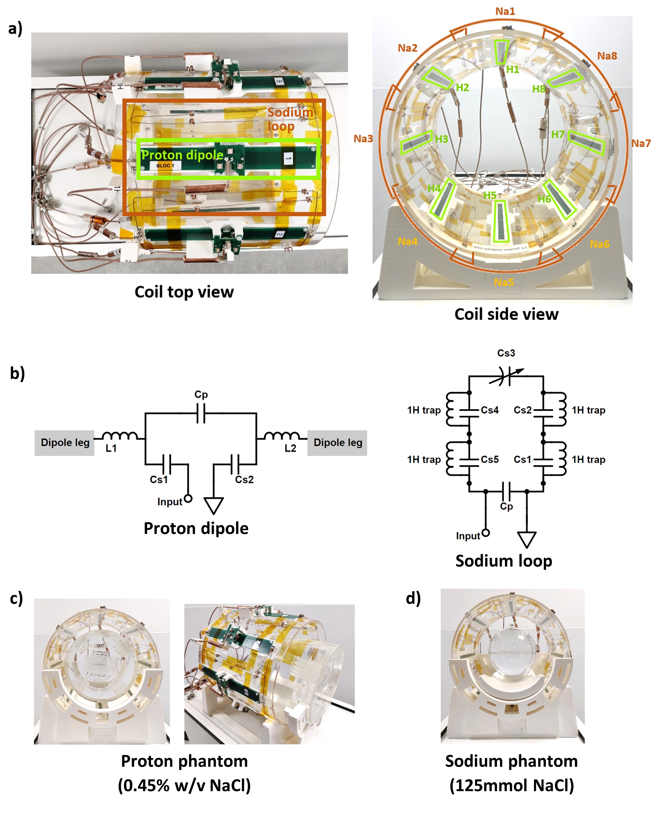
Fig.1. a) Photos of the coil from top and side view. The
coil is built on acrylic cylinder (diameter = 30cm, length = 30cm) and supported
by a 3D-printed holder. Eight 1H Tx/Rx dipoles and eight 23Na Tx/Rx loops are distributed symmetrically.
Each 1H dipole is placed in the centre of the 23Na loop. b) Circuit
diagrams for proton dipole and sodium loop. c) Cylindrical phantom
(diameter = 21cm, length = 21cm, 0.45 w/v NaCl) for proton measurements. d)
Spherical phantom (diameter = 15cm, 125 mmol NaCl) for sodium characterisation.
A 3D-printed holder is designed for phantom alignment.

Fig. 2. S-matrix of a) proton dipoles at 297.2MHz from bench measurements with cylindrical phantom (diameter = 21cm, length = 21cm) filled with 0.45% w/v NaCl recorded from VNA; b) sodium loops at 78.6MHz from bench measurements with spherical phantom (diameter = 15cm) filled with 125 mmol NaCl recorded from VNA.
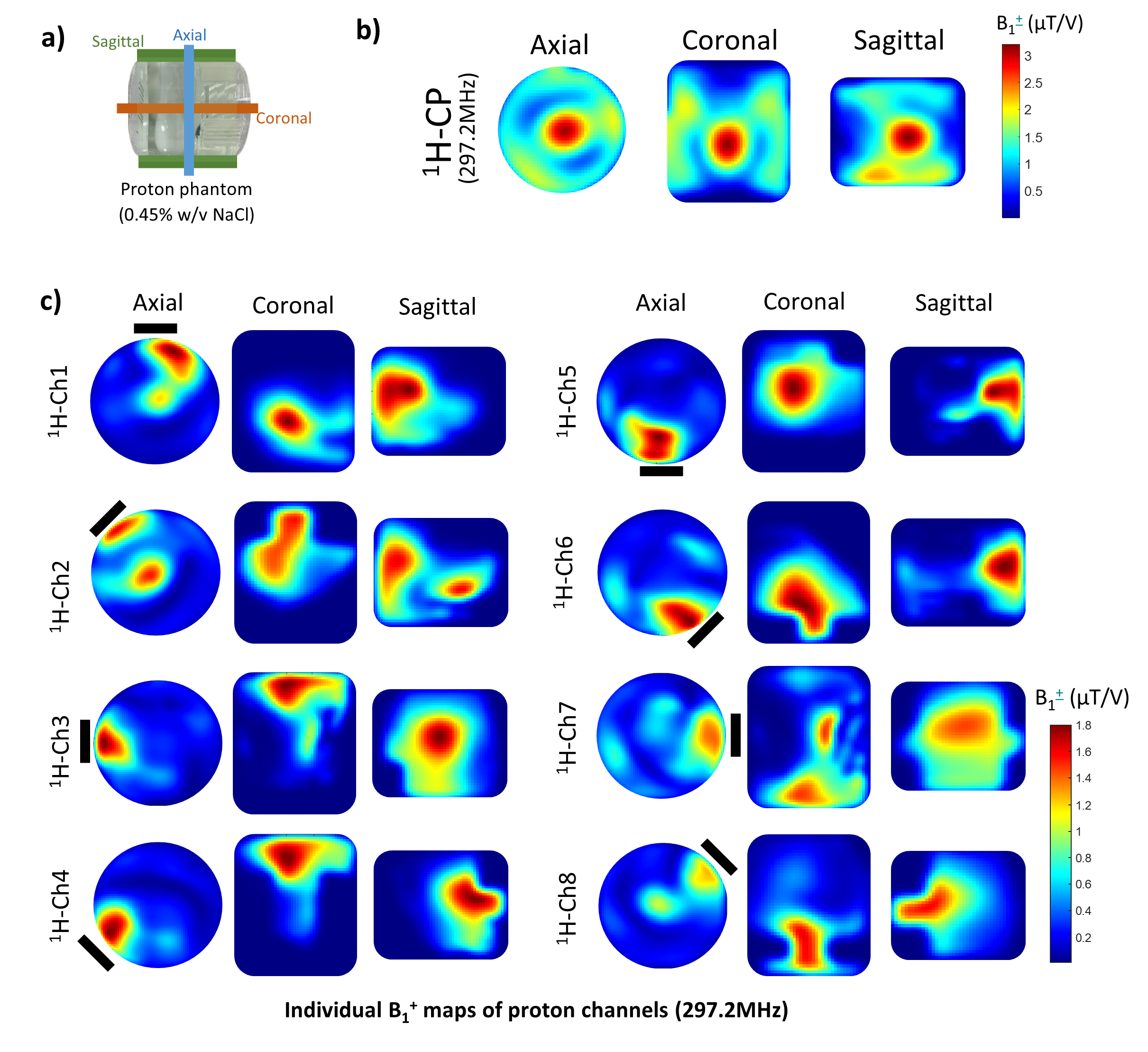
Fig. 3. 1H
B1+ maps from
a) three orientations of the phantom; b) 1H B1+
maps of combined proton channels of the in-house built coil in CP mode; c) 1H B1+ maps of individual proton dipoles. The position of individual channels is
indicated by continuous black lines. B1+ maps were
calculated based on 3D AFI sequence and 3D GRE sequence in CP mode and individual
channels. The scan was carried out on the 7T scanner with a cylindrical phantom
(diameter = 21cm, length = 21cm) filled with 0.45 w/v NaCl. The results are
masked to remove the artefact in the phantom.
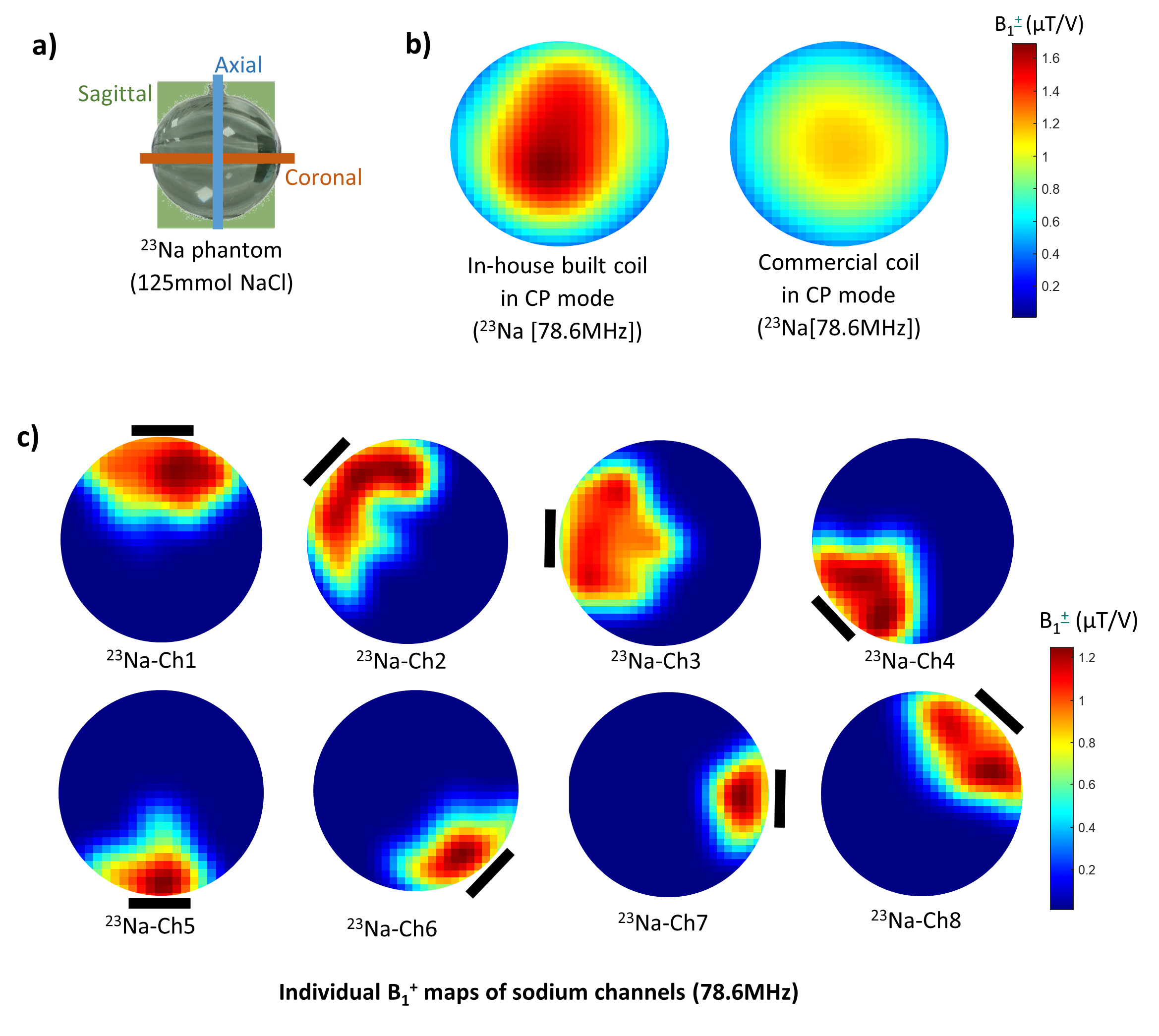
Fig. 4. 23Na
B1+ maps from the middle axial slice as illustrated
in a). b) Comparison of 23Na B1+ maps from combined
sodium channels of the in-house built coil and the commercial coil in CP mode;
c) 23Na B1+ maps of individual sodium loops. The
position of each channel is indicated by continuous black lines. The
scan was carried out on the 7T scanner with a spherical phantom (diameter =
15cm) filled with 125 mmol NaCl. All B1+
maps were calculated by the double-angle method from 2D GRE sequences and
smoothed with a Gaussian filter (σ = 2).
DOI: https://doi.org/10.58530/2023/5080