5076
The Lord of the EndRings: A roadmap for the design and construction of a Tx/Rx 31P birdcage head coil and feed network at 3 Tesla
Peter Truong1, Helmut Stark2, Agessandro Abraham3,4, Lorne Zinman3,5, and Jamie Near1,6
1Physical Sciences Research Platform, Hurvitz Brain Sciences Program, Sunnybrook Research Institute, Toronto, ON, Canada, 2Stark Contrast, Erlangden, Germany, 3Evaluative Clinical Sciences, Hurvitz Brain Sciences Research Program, Sunnybrook Research Institute, Toronto, ON, Canada, 4Department of Medicine (Neurology), Sunnybrook Health Sciences Centre and University of Toronto, Toronto, ON, Canada, 5Institute of Medical Science and Rehabilitation Sciences Institute, University of Toronto, Toronto, ON, Canada, 6Department of Medical Biophysics, University of Toronto, Toronto, ON, Canada
1Physical Sciences Research Platform, Hurvitz Brain Sciences Program, Sunnybrook Research Institute, Toronto, ON, Canada, 2Stark Contrast, Erlangden, Germany, 3Evaluative Clinical Sciences, Hurvitz Brain Sciences Research Program, Sunnybrook Research Institute, Toronto, ON, Canada, 4Department of Medicine (Neurology), Sunnybrook Health Sciences Centre and University of Toronto, Toronto, ON, Canada, 5Institute of Medical Science and Rehabilitation Sciences Institute, University of Toronto, Toronto, ON, Canada, 6Department of Medical Biophysics, University of Toronto, Toronto, ON, Canada
Synopsis
Keywords: Non-Array RF Coils, Antennas & Waveguides, Challenges
Join us as we take you on a journey in the development of a Tx/Rx 31P birdcage head coil. Even though there is a wealth of available knowledge explaining the theory of MRI RF coil design, there are many unforeseen situations one will encounter in practice. The road for coil development is filled with many valuable lessons. We hope to provide a practical guide for new builders by describing our experiences in coil design, construction, and troubleshooting.Introduction
There is a wealth of available knowledge explaining the theory of MRI RF coil design. However, many of the practical realities are often not covered by theory. From conception to scanning there are still plenty of possibly unforeseen and overlooked bumps along the way. The goal of this abstract is to provide a practical guide for new builders by describing our experiences in the design and construction of a Tx/Rx 31P birdcage head coil.An Unexpected Journey
Our goal was to design a Tx/Rx 31P birdcage coil1 for human head imaging on a 3T Siemens Prisma-XR (Erlangen, Germany). We opted for a low-pass coil design with 12 rungs and two capacitor gaps on every rung. The network was designed using the dip-trace software (diptrace.com) and printed on flexible PCB. Initial estimates for the capacitor values were obtained using the Birdcage Builder web application (https://research.med.psu.edu/departments/center-for-nmr-research/software/birdcage-builder-web-app/). After populating the coil with the initial capacitance estimates using non-magnetic ceramic capacitors rated for 2.5 kV (Knowles Syfer), further fine tuning was done using variable capacitors (Voltronics) to reach the desired resonance frequency (49.87 MHz). 31P BALUNs were placed at each drive port, which were formed by winding semi-rigid coaxial cable into inductors and bridging with a parallel capacitor to make an LC tank. The birdcage was surrounded by a copper mesh to minimize radiative losses – a choice which later proved to be troublesome.To interface our coil with the scanner, a feed network consisting of a TR switch and quadrature hybrid (Anaren 10230-3) were required2 (Figure 1).
Fellowship of the Switch
We managed to run an FID scan using the above setup. However, after a few short scans, we failed to acquire any signal. It was discovered that the 50-ohm terminating resistor from the TR switch was blown. Our TR switch was insufficient in handling the RF pulse power during scans. Thus, a high-power resistor rated for 150W was sought out. To aid in heat dissipation, a heatsink was attached to the resistor. Passive protection circuits were added in parallel to each PIN diode in the event where they fail (Figure 2).This time, two TR switches were built: One for between the ISOL port of the quad hybrid and the scanner Rx port (to protect the scanner Rx port against high transmit voltages) and one for between the Tx port of the scanner and the IN port of the quad hybrid (to prevent noise from the transmitter amplifier from coupling into the signal during Rx) (Figure 2). The Tx and Rx TR switches offered us -34 dB and -38 dB of isolation, respectively.
For an added layer of modularity between our coils, we've modified a pre-existing Siemens Tim cable and plug to connect to our feed network via DSUB connection. This allows us to freely use switch between different coils and feed networks using the same cable.
The Two Frequencies
With our new and improved feed network, we were ready to test out and see if the changes offered us improved performance. Note that since our coil was not dual tuned to 1H, we needed to use the system body coil for 1H localizers and shimming. Upon plugging our feed network into the scanner, we were met with an ominous red LED on the Tim coil interface. This turned out to be due to our lack of a preamplifier in our feed network. With it installed, this issue was resolved. We continued onto image acquisition, only for us to be met with our next issue - not enough signal on the proton channel to run routine preparation and localizers. We came to the realization that our RF shield was blocking the 1H RF transmission and reception of the system body coil!After removing the shield and re-tuning the coil, we tried once again to run a 1H localizer scan, only for it to fail yet again, this time during the adjustments. Now, instead of coupling to the shield, the 1H system body coil was coupling to the phosphorus coil itself! Our setup required another redesign to minimize coupling between the 1H system body coil and our 31P birdcage as shown in Figure 3.
Return of the Signal
Finally with the last round of upgrades to our coil setup (Figure 4), it was time to test out our coil once again. Our efforts were rewarded, as we were able to acquire spectra without any errors or issues! For the purposes of the studies we'll be conducting, we acquired a simple FID-CSI scan, processed results are seen in Figure 5.Conclusion
From start to finish, this journey took us exactly one year (with other obligations during the time as well). The path to develop of a functional coil comes with unforeseen practical difficulties along the way. However, every stumbling block is a valuable learning opportunity not often found in theory textbooks. And when additional support is needed, it is good to talk to people with experience. Helmut Stark, who works with the Siemens coil design group, provided consulting support for us on this project. We hope that by detailing our experience, it might help others avoid some of the mistakes we made.Acknowledgements
No acknowledgement found.References
[1] Hayes, Cecil E., et al. "An efficient, highly homogeneous radiofrequency coil for whole-body NMR imaging at 1.5 T." Journal of Magnetic Resonance (1969) 63.3 (1985): 622-628.
[2] Thapa, Bijaya, et al. “Design and Development of a General-Purpose Transmit/Receive (T/R) Switch for 3T MRI, Compatible for a Linear, Quadrature and Double-Tuned RF Coil.” Concepts in Magnetic Resonance Part B: Magnetic Resonance Engineering, vol. 46B, no. 2, 2016, pp. 56–65., https://doi.org/10.1002/cmr.b.21321.
[3] Provencher, S W. “Automatic quantitation of localized in vivo 1H spectra with LCModel.” NMR in biomedicine vol. 14,4 (2001): 260-4. doi:10.1002/nbm.698
Figures

Figure 1 - A) Diagram of our first setup. The feed network consisted of a commercial made quadrature hybrid coupler (Anaren 10232-3) and an in-house made TR Switch. B) Image of the TR switch and C) its schematic. The design consisted of a lumped element quadrature hybrid (pi-network design), and a pair of PIN Diodes (Cobham DH80106). A DC bias voltage would forward bias the PIN diodes during transmission which will prevent any leakage currents from entering the scanner receive port during Tx, offering -34 dB of isolation between the Tx and Rx ports during transmission.
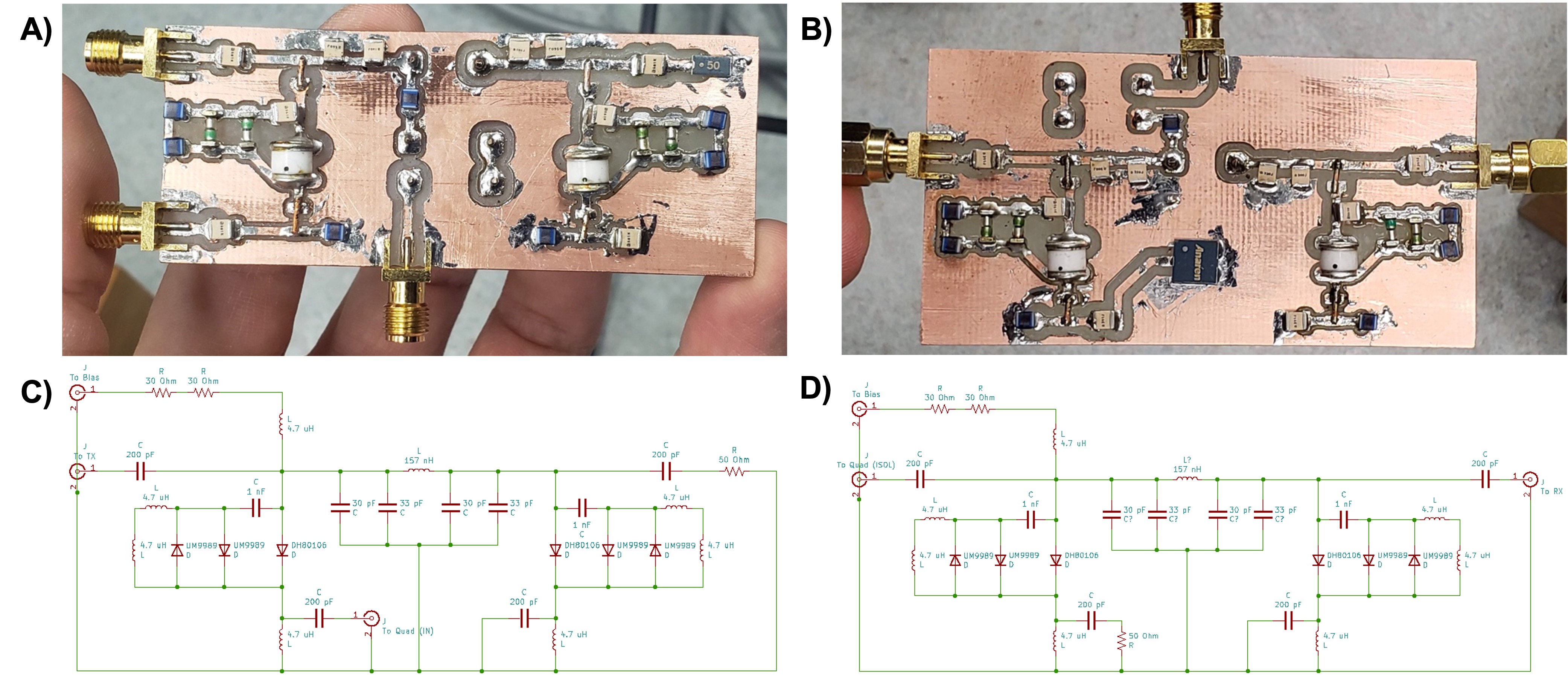
Figure 2 - The TR switches for Tx (A) and Rx (B) paths, along with their respective schematics (C, D). Passive protection circuits were added parallel to the PIN diodes. They are composed of a set of crossed switching diodes (Microsemi UM9989) with a DC blocking capacitor in series. Two 4.7uH inductors (Murata LHW2UAS4R7J00L) in series were placed in parallel to the passive diodes to short any charging currents from the capacitor.
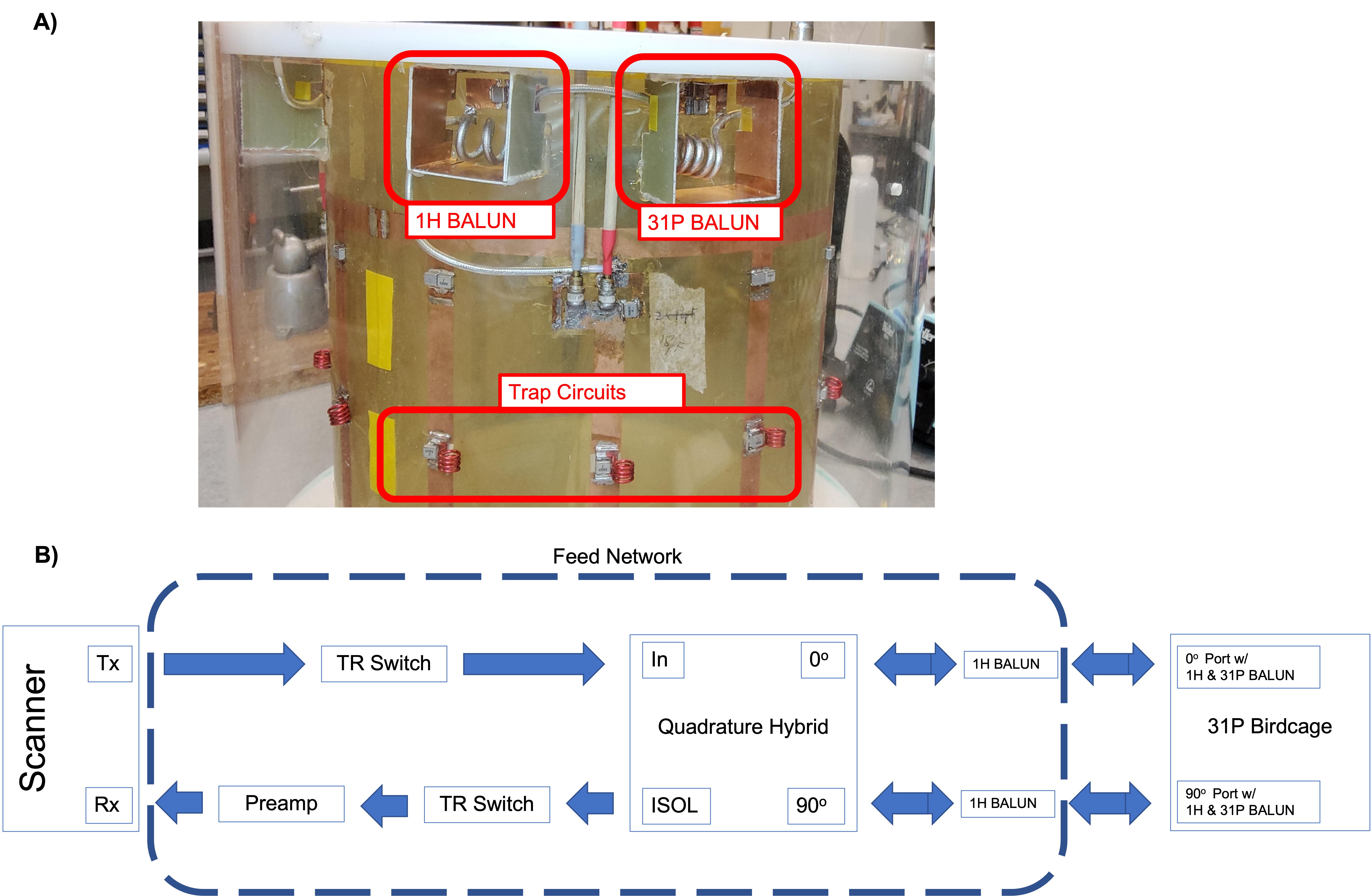
Figure 3 - A) To address the coupling between the body and 31P birdcage coils, trap circuits were placed in each rung of the birdcage and 1H BALUNs were placed in series after the 31P BALUN. B) Our finalized network. Updated are the inclusion of the TR switch in the Tx path, preamp prior to the Rx port of the scanner, 1H BALUNs placed in-line between the quadrature hybrid and coil.
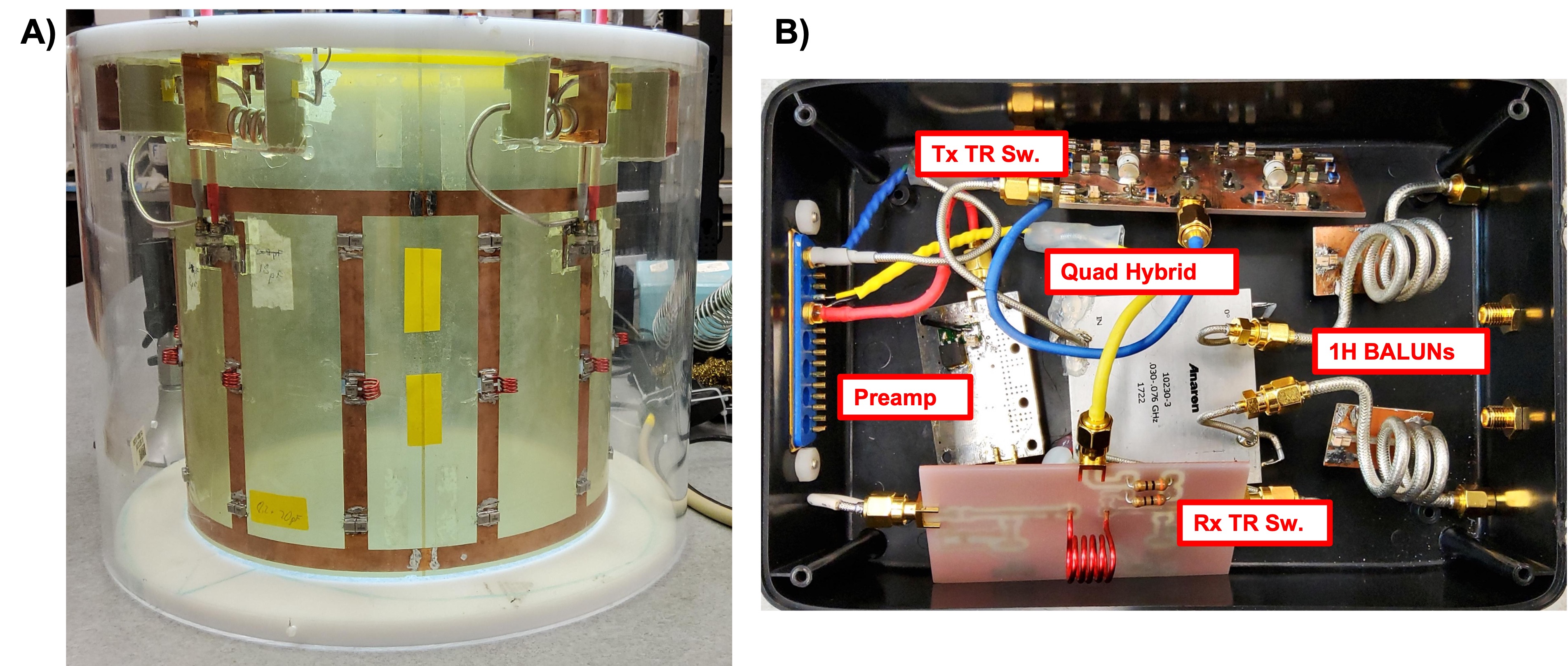
Figure 4 -Finalized versions of our 31P birdcage coil (A) and feed network (B).
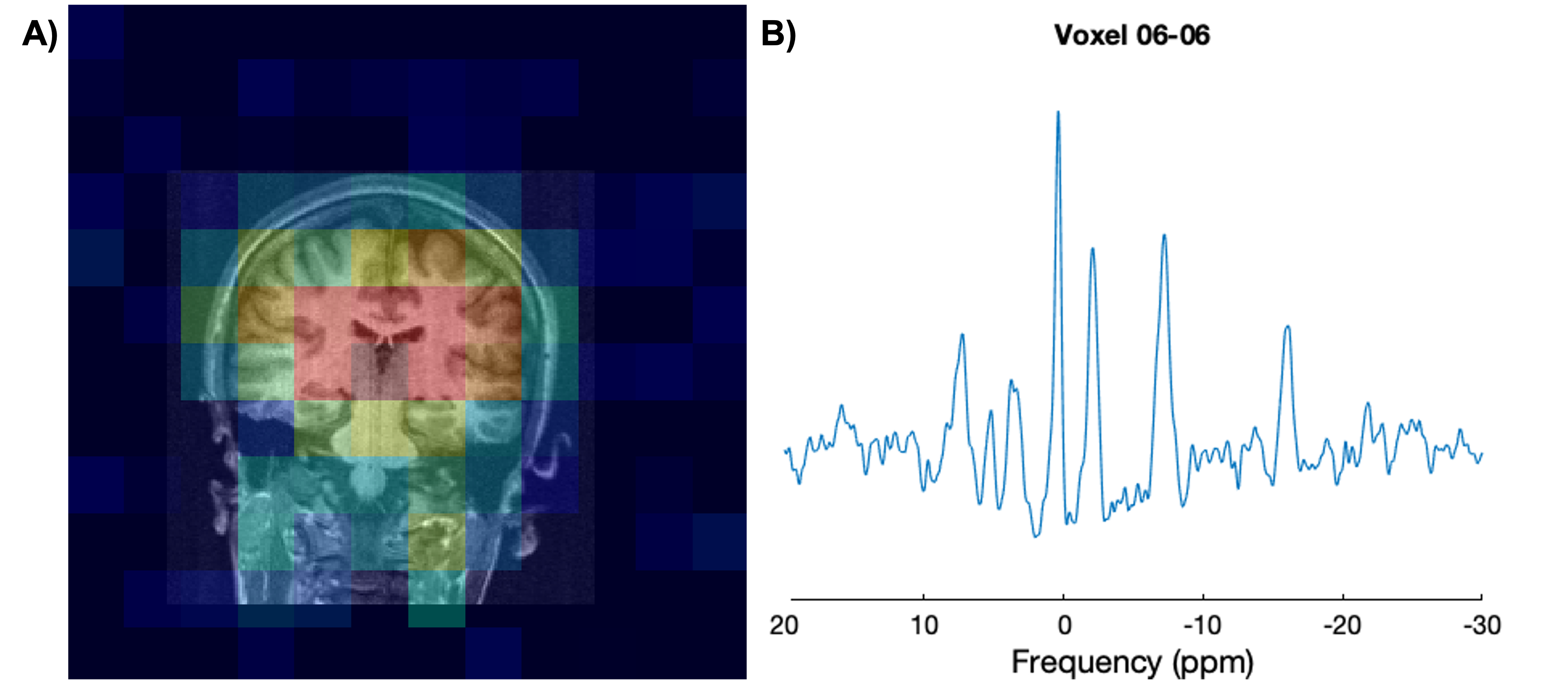
Figure 5 - A) Coronal slice overlaid with MRSI colour map for PCr. B) Processed spectrum from one voxel. Data was processed and visualized using FID-A (GitHub.com/CIC-methods/FID-A) and LCModel3 was used for analysis. Scan parameters were: TR=2s; TE=2.3ms; 2 averages acquired; spectral width = 3000 Hz; 2048 points acquired; CSI FOV = 300mm x 300mm; CSI slice thickness = 40 mm; CSI dimensions = 12x12, CSI slice placed on coronal plane; total scan time = ~9min.
DOI: https://doi.org/10.58530/2023/5076