5074
Overlapped or gapped multi-row self-decoupled transmit array: which is better?
Ming Lu1, Zhipeng Cao2,3, and Xinqiang Yan2,3
1College of Nuclear Equipment and Nuclear Engineering, Yantai University, Yantai, China, 2Vanderbilt University Institute of Imaging Science, Vanderbilt University Medical Center, Nashville, TN, United States, 3Department of Radiology and Radiological Sciences, Vanderbilt University Medical Center, Nashville, TN, United States
1College of Nuclear Equipment and Nuclear Engineering, Yantai University, Yantai, China, 2Vanderbilt University Institute of Imaging Science, Vanderbilt University Medical Center, Nashville, TN, United States, 3Department of Radiology and Radiological Sciences, Vanderbilt University Medical Center, Nashville, TN, United States
Synopsis
Keywords: Parallel Transmit & Multiband, High-Field MRI
This work is aiming to answer which multi-row self-decoupled array outperforms in parallel transmission to generate a uniform transmit RF field (B1+).Introduction:
Parallel transmit (pTx) arrays with multiple individual elements is a well-recognized solution to address the transmit field inhomogeneity and high local SAR at ultrahigh field. The widely used transmit array at 7 Tesla is a single-row design with eight elements equally distributed along the circumference. While such design performs well in the brain-only imaging, it meets challenges in applications that require long coverage, such as ASL and simultaneous brain and spinal cord imaging. Simple and robust designs, such as self-decoupled coils [1], are favorable in Tx arrays as they can ease the fabrication procedure, reduce the risk of component failure and alleviate performance variation with different subjections. When moving to multi-row Tx arrays, the self-decoupled coils could be arranged into two layouts, one is the overlapping between adjacent rows, and the other is the gap design in both longitudinal and circumferential directions. Compared to the gapped design, the overlapped array has the following apparent advantages, (1) additional freedom to decouple so there is no need to trade off in choosing Cmode; (2) slightly larger size for the same coverage and large coil-to-noise ratio. On the other hand, the gapped array has the following apparent advantages: (1) easy to fabricate as no geometry constraints are required; (2) unbalanced current along the arms that is beneficial for the transmit efficiency and the SAR efficiency. In addition to the apparent disadvantages and advantages of these two designs, there is a most important but not obvious criterion to evaluate transmit arrays - the parallel transmission performance. This work is aiming to answer which multi-row self-decoupled array outperforms in parallel transmission to generate a uniform transmit RF field (B1+).Method:
Coil modelFigure 1 shows the simulation models and circuit diagrams of a 16-channel (2x8) gapped and overlapped array. Each coil was mounted on an 29-cm-diameter acrylic tube. The longitudinal coverages of both coils are set to 29 cm. A copper-foil tube of 33 cm diameter and 34 cm length was used as RF shielding but not shown in Figure 1 for simplification. All coil elements in both arrays were well tuned to 298 MHz, matched to 50 ohm and decoupled. For the gapped self-decoupled Tx array, the initial values of all components were acquired using co-simulation method, following Yan et al [1]. For the overlapped array, the overlapped areas between coils in the top and bottom rows were carefully adjusted to minimize their inductive coupling. Since the optimal overlapping area is to some extent dependent on the loadings, the overlapping area between each pair of coils was manually adjusted. The EM simulation of the gapped array takes 21 hours using a DELL workstation (192 GB RAM, 24 core), while the simulation of the overlapped array takes 15 days.
pTx Algorithm
pTx or RF shimming performance was evaluated as the flip angle normalized RMS error (NRMSE, {√||Ax|-1|2 /Nx}) for a given SAR limit. The magnitude-least-squares (MLS) algorithms with a finite-difference (FD) regularizer was employed for multi slice shimming [2]. The cost function is min{||Ax|-1|2 +β1|x|2+β2|▽(Ax)|2}.
Results:
Figures 2A and 2B show the multi-slice (axial slices) shimming results of the 16-channel overlapped and gapped arrays, respectively. It is noticed from Figures 2A and 2B that the gapped array could generate more uniform B1+ fields over the overlapped array. Especially, for the overlapped array, there is an inevitable null in the central slice even using the finite-difference regularizer. Figure 2C plots the trade-off relationship between flip angle error and RF power (L-curve) of the two Tx arrays. The gapped array has notably less RF power disposition compared to the overlapped array. For example, the RF power disposition of the gapped array is 6.38 a.u. for an RMSE of 5.2%, while that of the overlapped array is 8.92 a.u. for a similar RMSE of 5.9%. It is expected that two arrays exhibit similar uniform B1+ in multi-slice shimming as they have similar geometries and layouts. The low SAR in the gapped array could be attributed to the unbalanced current along the arm conductors that improves the B1+ SAR efficiency, i.e., reduce the SAR for the same B1+ strength.Overall, we found that the gapped array outperforms overlapped array in pTx or RF shimming performance. Considering that the gapped array is much easier to fabricate in practice, we suggest using gapped instead of overlapped in multi-row self-decoupled Tx arrays. Note that the feed port of the gapped self-decoupled coil should be carefully chosen to maximize the transmit performance. This investigation is based on the assumption that all coils can be controlled independently. This is practical that some scanner is equipped with 16 transmit channels that can drive all coils independently. For the standard 7T scanner with 8 transmit channels, further studies will be needed to find the optimal way to combine 16 coils into 8 virtual coils.
Acknowledgements
This work was supported by NIH EB R01 031078. Zhipeng Cao and Xinqiang Yan contributed equally to this work. This work was performed during the period of Dr. Ming Lu's visit to Vanderbilt University institute of imaging science.References
- Yan X, Gore J C, Grissom W A. Self-decoupled radiofrequency coils for magnetic resonance imaging[J]. Nature communications, 2018, 9(1): 1-12.
- Paez A, Gu C, Cao Z. Robust RF shimming and small‐tip‐angle multispoke pulse design with finite‐difference regularization. Magnetic Resonance in Medicine, 2021, 86(3): 1472-1481.
Figures
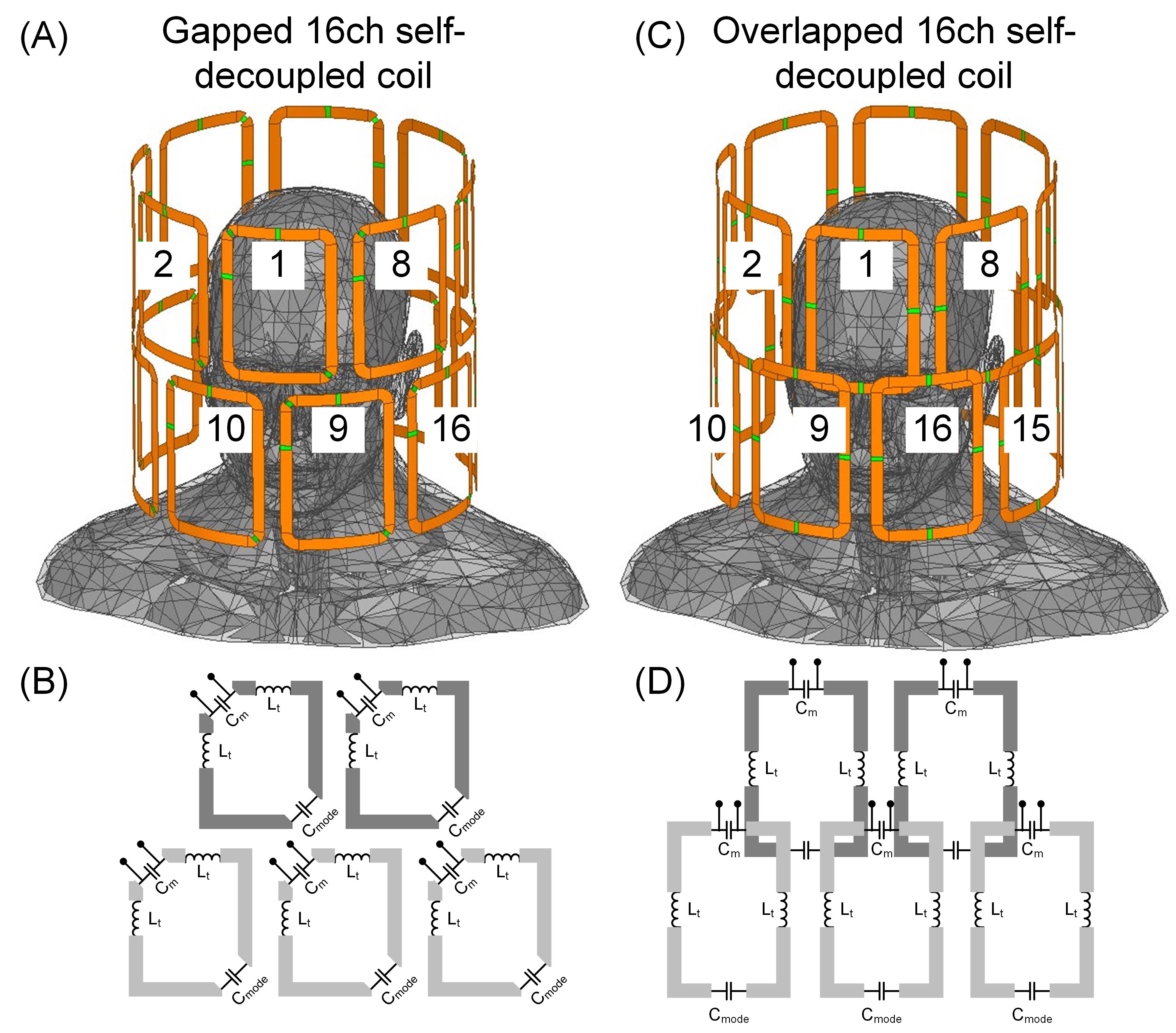
Figure 1 Simulation models and circuit diagrams of a 16-channel
(2x8) gapped array (A and B) and a 16-channel (2x8) overlapped array (C and D) . For both
arrays, the bottom row was rotated 22.5 degree compared the top row to provide
more freedoms to manipulate the B1+ field in the transverse slices. For the
overlapped array, the coil was feed at the top conductor and currents along the
two arm conductors are balanced. For the gapped array, the coil was feed at the
top-left corner so the current along the left arm conductor is strong than that
of the right arm conductor.
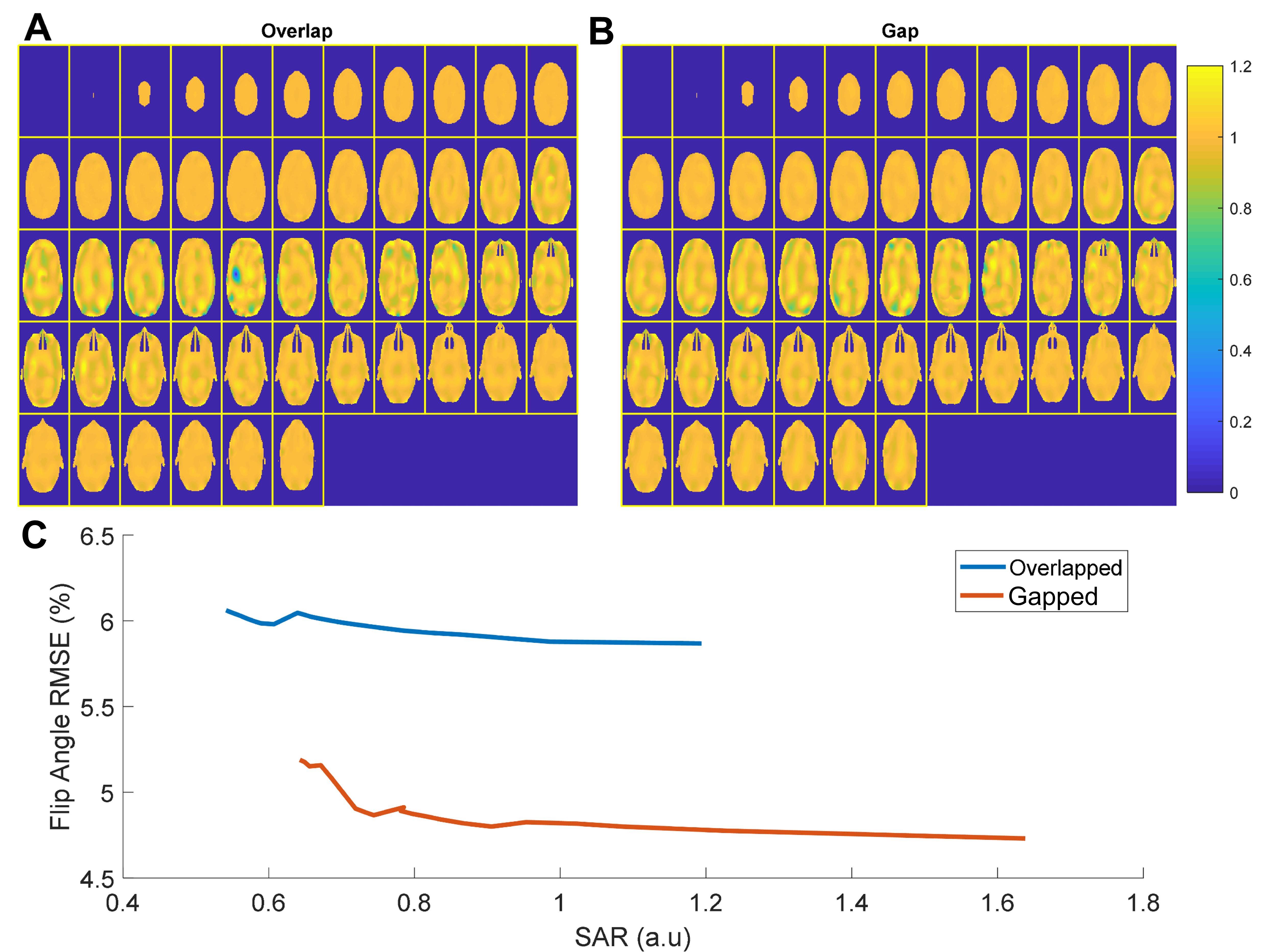
Figure 2 A and B: Multi-slice shimming results using FD-MLS with the
gapped transmit array (B) and the overlapped transmit array (A). C:
L-curves for RF shimming using the gapped array and using the overlapped array.
DOI: https://doi.org/10.58530/2023/5074