5073
Helmet RF Applicator for Enhancing Focal RF Power Deposition in Thermal Magnetic Resonance of the Brain at 7T1Berlin Ultrahigh Field Facility, Max-Delbrück Center for Molecular Medicine in the Helmholtz Association, Berlin, Germany, 2Theoretische Elektrotechnik Institut Hochfrequenz- und Halbleiter-Systemtechnologien, Technische Universität Berlin, Berlin, Germany, 3Chair of Medical Engineering, Technische Universität Berlin, Berlin, Germany, 4a joint cooperation between the Charité Medical Faculty and the Max-Delbrück Center for Molecular Medicine, Berlin, Germany, 5Clinic for Radiation Oncology, Charite’ Universitätsmedizin, Berlin, Germany, 6MRI.TOOLS GmbH, Berlin, Germany
Synopsis
Keywords: RF Arrays & Systems, Interventional Devices, SAR distribution, Focal Heating, Hyperthermia, Brain Thermal MR at 7T
Thermal Magnetic Resonance (ThermalMR) uses an RF-applicator to add a thermal intervention dimension to a diagnostic imaging device. Optimizing the performance of RF applicator configurations can eventually improve the performance of ThemalMR. This work examines the feasibility of multi-channel RF applicators using broadband Self-Grounded Bow-Tie (SGBT) antenna building blocks. The focus is on enhancing focal RF power deposition in a target volume by using a multi-channel helmet RF array configuration versus conventional annular RF arrays. Our preliminary findings obtained for the human head voxel model Duke show improved target coverage of high SAR10g and high temperature for the helmet configuration.Introduction
MRI is a mainstay of diagnosis, but adding a thermal intervention dimension is conceptionally appealing for localized thermal therapy as an adjuvant to cancer chemo- and radiotherapy1. ThermalMR2 exploits localized radiofrequency (RF) power deposition in a target volume (TV) by adjusting the electric field components of multiple independent RF sources. This is done by setting the individual E-fields to constructively superimpose in the TV, while canceling out each other outside the TV to preserve healthy tissue. Ultrahigh field (UHF) MRI is an excellent fit for Thermal MR as it operates at shorter wavelengths than conventional MRI, which can provide better localized temperature manipulation along with diagnostic imaging. Optimizing the performance of RF building blocks and RF applicator configurations can improve the performance of ThemalMR. Recognizing this opportunity, this work examines the advantages of a helmet RF applicator3 over an annular RF array for diagnostic MRI and hyperthermia application in the brain.4-7Methods
Electromagnetic field (EMF) simulations where performed in CST Microwave Studio (CST Studio Suite 2020) at 297.2 MHz.3,4,6,7 The maximum Specific Absorption Rate (SAR) in a hypothetical TV was benchmarked for two RF array configurations, each assembled from ten broadband Self-Grounded Bow Tie antenna (bbSGBT)3) building blocks: a 10-channel TX array using a symmetrical annular arrangement; a helmet configuration with 8 channels in a symmetrical annular array plus two channels placed above the head rotated 90° (Figure1A).SAR calculations were averaged over 10g (SAR10g) of tissue/phantom material according to IEEE/IEC standard 62704-1.8 EMF simulations of both RF applicators were performed using a phantom mimicking the properties of brain tissue (at 297 MHz and 434 MHz) and the head of the human voxel model Duke (at 297 MHz).9 The target-volume (TV) was i) an ellipsoid (Ø=2cm) placed in the center plane of the annular arrays and the phantom, and ii) a cubic TV (size=3cm, depicted by the green square, 40W/kg<SARavg<80W/kg), and for a safe margin (SARmax<40 W/kg, size=5cm, depicted by the red borderline). To mimic a realistic clinical scenario, a voxel model was generated from a computed tomography head scan of a patient with an intracranial glioblastoma multiforme. The tumour (volume=172mL, σtumor=1.15 S/m, εrtumor=66.5)2 was imported into the head geometry of the patient (head mass=3.68kg) using Sim4life (ZMT). Constructive E-field interference in the TV was achieved with a focusing method10. Target coverage (TC) was defined as the percent volume covered by 25% of the maximum SAR10g, as an indicator of homogeneity. Simulation results were compared for a defined TV in 4 locations in the brain; statistical comparisons were based on a sampling of ~700 TVs in the brain (step size=3mm). Temperature distribution maps were obtained (Sim4Life) by using the Hyperthermia optimizer tool for focusing SAR10g together with the ESHO standards for thermal properties and boundary conditions for head tissues.11 Cumulative histograms of the 10%, 50% or 90% TV covered by which temperature is defined by T10, T50, and T90, respectively.
Results
The design of the annular and helmet RF applicators on the phantom (Figure1A) and Duke (Figure1B) are shown. Figure1C shows that the helmet configuration had greater maximum SAR10g in the center of the phantom compared to the annular array: 2.5 vs. 2.3 W/kg at 297 MHz; 6.31 vs. 3.57 W/kg at 434 MHz. The SAR10g distribution showed that the helmet applicator had better focal point quality than the annular array, due to superior coverage of the phantom. The helmet RF applicator had a mean target SAR10g=62 W/kg versus 54.1W/kg for the annular array (TC 100 vs. 97%), within a TV in the brain of the human voxel model (Figure1D).Figure2A shows SAR10g distributions for 4 TVs in the brain. The mean target SAR10g values (MTS) from the helmet array were superior to those from the annular array (Table1). The performance advantage of the helmet array over the annular array is highlighted by the radar plot showing MTS, Max SAR10g in TV, in HV and their ratio normalized values (Figure2B).
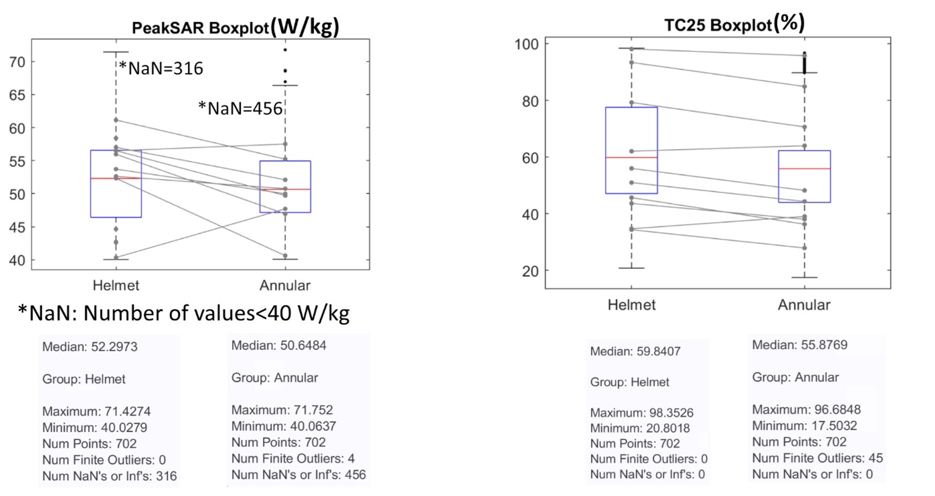
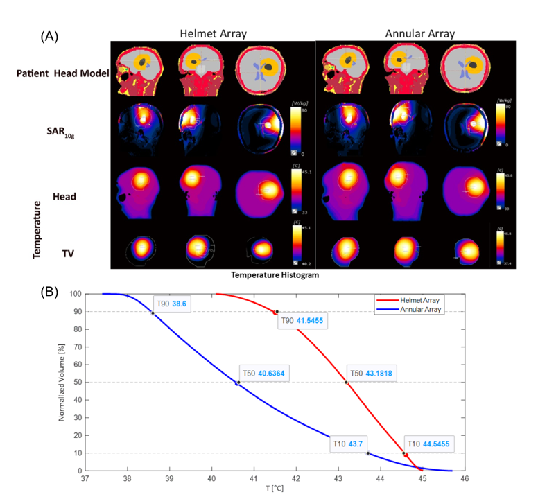
Statistical comparisons from >700 TVs sampled in the brain show higher peak SAR10g in the TV and TC for the helmet array versus the annular array (Figure3). Temperature distribution maps obtained for a realistic TV modeled from a patient with glioblastoma multiforme show that the helmet array resulted in a higher mean temperature than the annular array for the same total input power (Figure4A). The Helmet array showed superior temperature performance than the annular array (Figure4B).
Discussion and Conclusion
ThermalMR integrates RF-induced heating, in vivo temperature mapping using MR thermometry, anatomical and functional imaging in a single, multi-purpose RF-applicator. Enhancing localized SAR10g in a TV requires high-density antenna arrays. This presents a challenge for ThermalMR of the head due to the small surface area. The helmet RF applicator takes advantage of two additional bbSGBT antennas placed above the head, directed to contribute both to MRI, and to RF-induced heating. This study demonstrates that the helmet RF applicator facilitates a ~10% improvement of maximum SAR10g in the TV versus the annular array, with enhanced TC. Our numerical simulations provide a technical foundation for implementation of the helmet array configuration, and offer a springboard for ThermalMR-based therapy of brain tumours.Acknowledgements
This project has received funding from the European Research Council (ERC) under the European Union's Horizon 2020 research and innovation program under grant agreement No 743077 (ThermalMR) and from the Innovative Training Network (ITN) H2020-MSCA-ITN-2020-955625 of the Marie Skłodowska-Curie Actions of the European Union.
References
1. Wust, P., et al. Hyperthermia in combined treatment of cancer. The lancet oncology 3, 487-497 (2002).
2. Oberacker, E., et al. Patient-Specific Planning for Thermal Magnetic Resonance of Glioblastoma Multiforme. Cancers (Basel) 13(2021).
3. Eigentler, T.W., et al. Wideband Self-Grounded Bow-Tie Antenna for Thermal MR. NMR Biomed 33, e4274 (2020).
4. Winter, L., et al. Design and evaluation of a hybrid radiofrequency applicator for magnetic resonance imaging and RF induced hyperthermia: electromagnetic field simulations up to 14.0 Tesla and proof-of-concept at 7.0 Tesla. PLoS One 8, e61661 (2013).
5. Winter, L., et al. Magnetic resonance thermometry: Methodology, pitfalls and practical solutions. Int J Hyperthermia 32, 63-75 (2016).
6. Han, H., et al. Multi-Channel RF Supervision Module for Thermal Magnetic Resonance Based Cancer Therapy. Cancers (Basel) 13(2021).
7. Oberacker, E., et al. Radiofrequency applicator concepts for thermal magnetic resonance of brain tumors at 297 MHz (7.0 Tesla). Int J Hyperthermia 37, 549-563 (2020).
8. IEEE Recommended Practice for Determining the Peak Spatial-Average Specific Absorption Rate (SAR) in the Human Head from Wireless Communications Devices: Measurement Techniques. IEEE Std 1528-2013 (Revision of IEEE Std 1528-2003), 1-246 (2013).
9. Christ, A. The virtual family project-development of anatomical whole-body models of two adults and two children. Proc. 23rd Annual Review of Progress in Applied Computational Electromagnetics (ACES) 2007 (2007).
10. Kuehne, A., Oberacker, E., Waiczies, H. & Niendorf, T. Solving the time-and frequency-multiplexed problem of constrained radiofrequency induced hyperthermia. Cancers 12, 1072 (2020).
11. Paulides, M.M., et al. ESHO benchmarks for computational modeling and optimization in hyperthermia therapy. Int J Hyperthermia 38, 1425-1442 (2021).
12. Kimball, R. Your Brain: An Introduction to Its Anatomy. (2021).
Figures
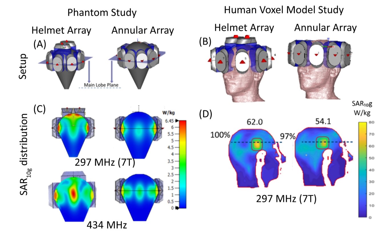
Figure1. Setup: Illustration of the design of the helmet and annular RF applicators on the phantom (A) and the head of the human voxel model Duke(B). Phantom Study: SAR10g distributions shows higher coverage and higher value for helmet array. Increasing the frequency also magnifies the SAR value in the center of phantom(C). Human Voxel Model Study: Higher mean SAR10g (W/kg) values annotated on top of each figure and higher TC(%) values annotated next to each figure for helmet array are obtained(D).
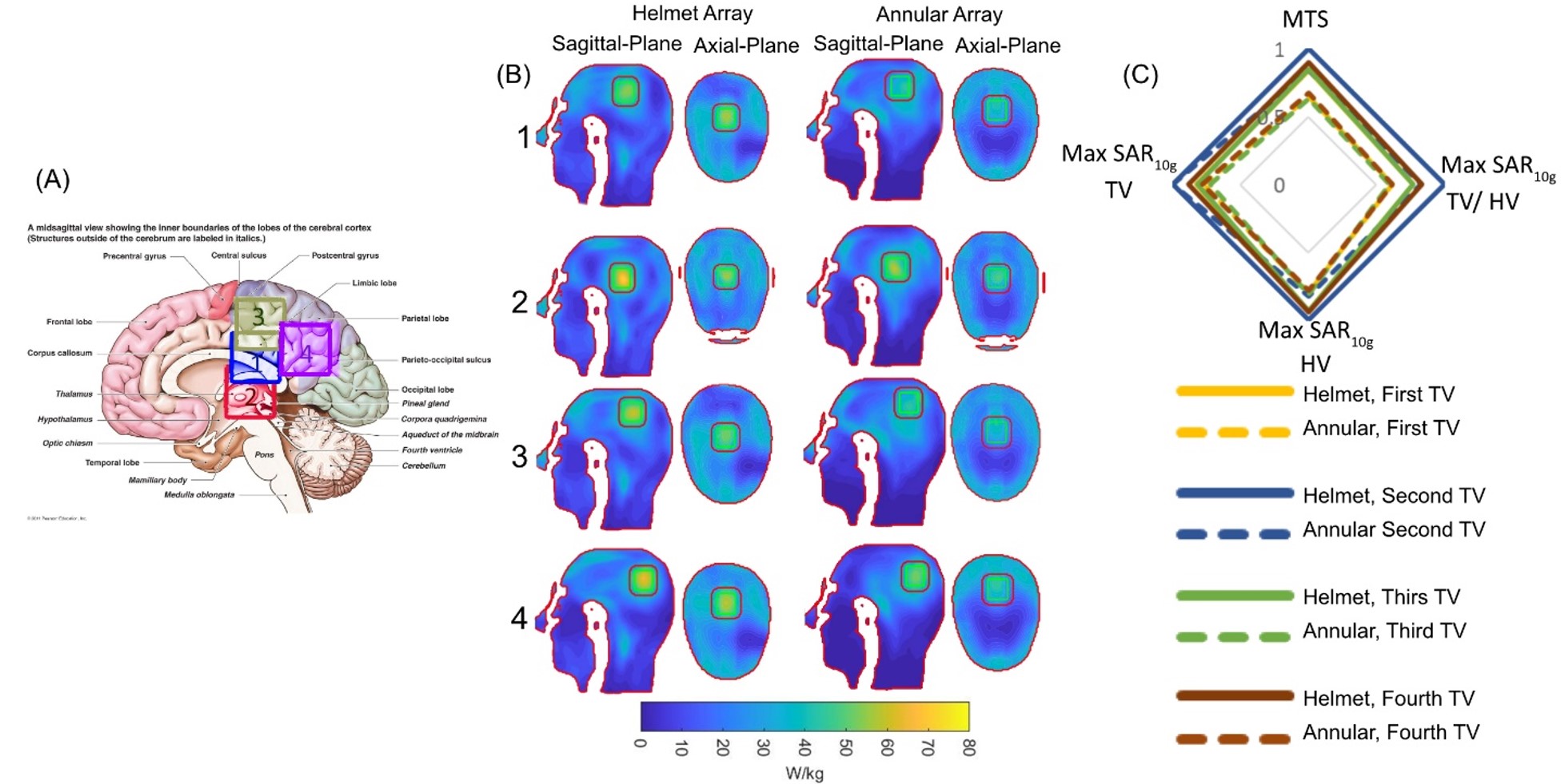
Figure2: Illustration of the TV locations 1-4 (TV1 in the limbic lobe and postcentral gyrus, TV2 in Thalamus region, TV3 in the corpus callosum and limbic lobe, TV4 in the parietal lobe of the brain) defined by rectangles (left) 12. SAR10g distribution inside the human head voxel model Duke obtained for the helmet and annular array for sagittal and axial planes through the brain (middle). Radar diagram for MTS, Max SAR10g in TV, in HV and their ratio for helmet (lines) and annular (dash lines) arrays demonstrating the performance gain of the helmet array versus the annular array (right).
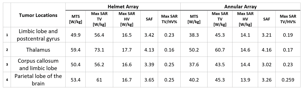
Table1: Maximum, and mean target SAR10g values inside the Tumor and healthy regions for four regions inside the brain inside the human head voxel model Duke