5072
Dielectric Loaded Stretchable and Flexible Surface RF Coil1School of Biological and Health Systems Engineering, Arizona State University, Tempe, AZ, United States
Synopsis
Keywords: RF Arrays & Systems, Phantoms, Receive coil, flexible coil, loaded coil
This study presents a novel receive radiofrequency coil that enhances the signal-to-noise-ratio (SNR) and field-of-view (FOV) in magnetic resonance images. The fabricated coil is loaded by a mixture of dielectric material (TiO2) and an elastomer offering stretchability and flexibility. The functionality of the coil compared to a typical surface coil was assessed using phantom imaging at 7T. The SNR (in dB), signal intensity, and uniformity are improved by 14.75%, 25%, and 87.76% by using a TiO2-loaded coil, respectively. This design method will be invaluable for uneven sample shapes and a very close place to a subject.
Introduction
Unlike volume coils that are designed to generate homogeneous radiofrequency (RF) fields inside the subject and are used as both transmit and receive coils, surface coils are mainly used as a receive coil with higher signal-to-noise ratio (SNR) in a region near to the coil.1 In the receive coils, it is critical to place the coils as close as possible to the subject, which resulted in designing flexible and stretchable coils. Screen-printed coils are fabricated as a highly flexible coils to fit the subject, particularly irregular subjects.2,3 Additionally, dielectric materials have demonstrated good performance in increasing both the transmitted and received B1 fields, specifically in regions with intrinsically low sensitivity caused by high frequency and geometry.4,5,6 In this study, we proposed a new method of fabricating a surface receive coil, which is loaded with a Titanium-Dioxide (TiO2) based flexible and stretchable dielectric substrate, and evaluated its performance at 7T. The dielectric loaded silicon elastomer substrate has a strong restoring force, and it is possible to bring a coil to its original shape after stretching and bending.Method
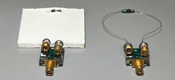
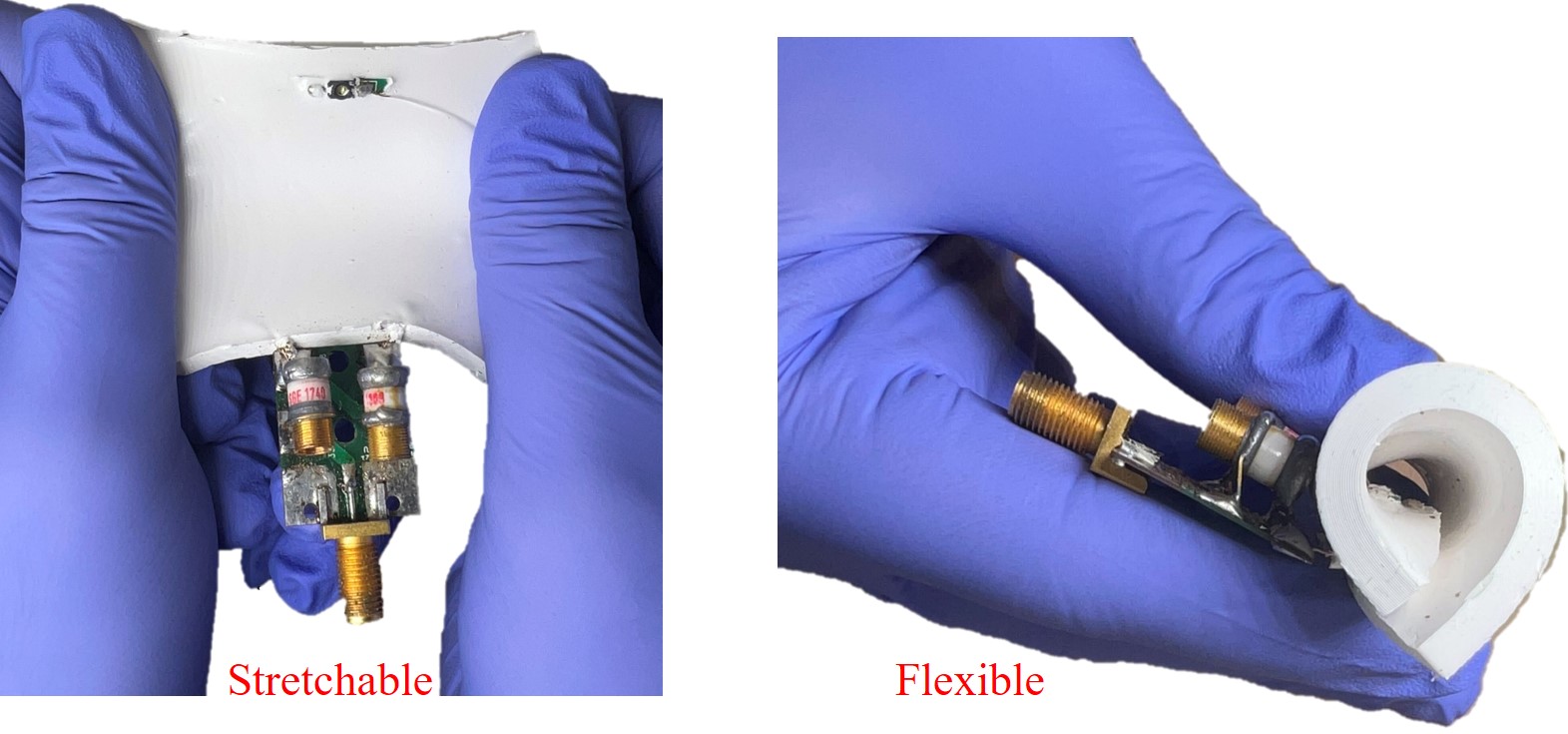
For fabricating dielectric loaded coil, high dielectric TiO2 powder was dispersed inside a silicon elastomer (Ecoflex-Series, Smooth-On, Macungie, PA) to make an elastic substrate with 20% (weight of powder to weight of final solution) concentration. The solution was vacuumed for 5 minutes to eliminate air bubbles inside it, and then poured inside a 3D printed mold with 50 mm width, 50 mm length, and 5 mm depth, in a way that fills 75% of it. The coils were made up of a 28-gauge cupper wire, and their diameters were 50 mm. One of the coils was placed on the cured TiO2 inside the mold, and the solution with the same concentration was poured on the coil to entirely cover the coil with the dielectric material. As shown in Fig.1, two identical single loop coils with the end capacitor were built, and they were tuned and matched for 7T using the L-Matching network with a Vector Network Analyzer (VNA) (FieldFox N9923A, Keysight Technologies, USA). Fig.2 demonstrates the stretchability and flexibility of the final TiO2 loaded coil. For the image comparison, the coils were in the same distance from the phantom to check the effect of the dielectric loaded coil structure. The 7T MR images were performed at Barrow Neurological Institute - Arizona State University (BNI-ASU) with the use of a 7T small-animal, 30-cm horizontal-bore magnet and a BioSpec Avance III spectrometer (Bruker, Billerica, MA) with 116-mm high-power gradient set (600 mT/m).Results and Discussion
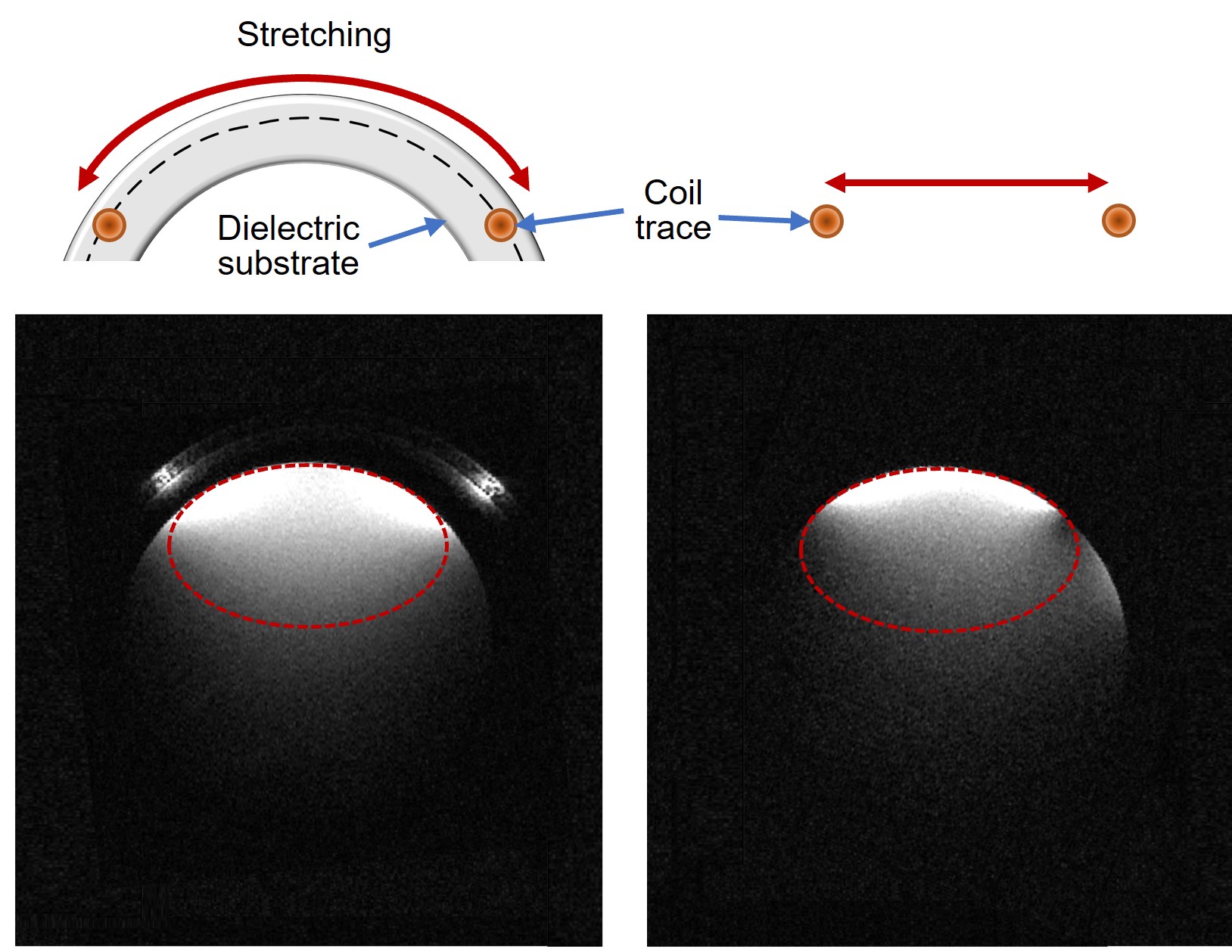
Five slices with 1 mm thickness were imaged using a Fast-Low- Angle-Shot (FLASH) Sequence with 350 ms repetition time (TR), 5.4 ms echo time (TE), 20 degrees flip angle(α), and 60 × 60 mm field-of-view (FOV). A Bruker linear birdcage coil was used for acquiring the images and the FLASH sequence used 400 W of peak power. A relatively large phantom with 50 mm diameter and 100 mm length was used for this experiment. The aim of this study was to evaluate the impact of dielectric loaded flexible coil on SNR, signal intensity, and uniformity. We analyzed the imaging data for the area near the coil (determined by the red elliptic in Fig.3) and the whole phantom. In the whole phantom analysis, an 18.29 % increase (from 10.08 dB to 12.11 dB) in SNR and 20.1% increase in Mean Signal Intensity (MSI) were observed by using a flexible dielectric loaded coil. Furthermore, 14.75% improvement (from 14.06 dB to 16.3 dB) in SNR and 25% enhancement in MSI was obtained in the region near the coil. Uniformity calculation using a formula of 2×min/(max+min) for near coil region shows 87.76% improvement in image acquired by TiO2 loaded coil. As is shown in Fig.3, the use of a TiO2 loaded coil expands the field of view. Further studies are being conducted on the other dielectric materials and coil structures to improve the performance of dielectric loaded coils with invisibility, to gain a better understanding of the limitations of application, and to evaluate effects of a chemical change over time and field strength on coil efficiency. It is important to note that after stretching and bending the coil for the imaging, it regained its original shape with an elastic force of the dielectric substrate.Conclusion
A dielectric loaded stretchable and flexible coil was introduced and evaluated at 7T. For the area near the coil, the enhanced signal intensity with 25%, SNR with 14.75%, and uniformity with 87.76% were observed, and for the whole phantom image the improved signal intensity with 20.1% and SNR with 18.29% were obtained by using the dielectric loaded coil. This novel coil design will be applicable to wearable and patchable coil applications.Acknowledgements
This work was supported by the National Institute of Biomedical Imaging And Bioengineering of the National Institutes of Health under Award Number R00EB020058.References
1. Gruber B, Froeling M, Leiner T, Klomp DWJ. RF coils: A practical guide for nonphysicists. J Magn Reson Imaging. 2018;48(3):590-604. doi:10.1002/jmri.26187
2. Malko JA, McClees EC, Braun IF, Davis PC, Hoffman JC. A flexible mercury-filled surface coil for MR imaging. Am J Neuroradiol. 1986;7(2):246-247.
3. Corea JR, Flynn AM, Lechêne B, et al. Screen-printed flexible MRI receive coils. Nat Commun. 2016;7. doi:10.1038/ncomms10839
4. Webb AG. Dielectric materials in magnetic resonance. Concepts Magn Reson Part A Bridg Educ Res. 2011;38 A(4):148-184. doi:10.1002/cmr.a.20219
5. Haines K, Smith NB, Webb AG. New high dielectric constant materials for tailoring the B1+ distribution at high magnetic fields. J Magn Reson. 2010;203(2):323-327. doi:10.1016/j.jmr.2010.01.003
6. Teeuwisse WM, Brink WM, Webb AG. Quantitative assessment of the effects of high-permittivity pads in 7 Tesla MRI of the brain. Magn Reson Med. 2012;67(5):1285-1293. doi:10.1002/mrm.23108
Figures