5071
A high impedance radio-frequency system improves the decoupling between receiving coils in MRI
Yu-Lung Tang1, Hsin-Ju Lee2,3, and Fa-Hsuan Lin2,3
1Timwave Technologies Company Limited, Taipei, Taiwan, 2Sunnybrook Research Institute, Toronto, ON, Canada, 3University of Toronto, Toronto, ON, Canada
1Timwave Technologies Company Limited, Taipei, Taiwan, 2Sunnybrook Research Institute, Toronto, ON, Canada, 3University of Toronto, Toronto, ON, Canada
Synopsis
Keywords: RF Arrays & Systems, RF Arrays & Systems
The decoupling between coils significantly impacts the amount of independent information between channels in a receiver coil array. Using a pre-amplifier with a low input impedance is limited by the technology in achieving the lowest possible impedance, typically around a few ohms. Here we propose a strategy to improve the decoupling between coil elements in a receiver array by increasing the impedance of the coil system. Simulations and bench measurements show that increasing the impedance from a typical 50 ohm to around 1,000 ohm can increase the decoupling by 25 dB.Introduction
Receiver coil arrays with a high channel count enabled large field-of-view and enhanced signal-to-noise ratio images 1, which can be translated to parallel imaging for spatiotemporal resolution improvement 2, 3. A challenge in developing a coil array is to isolate between receive coils to maximize the localized sensitivity at each receiver coil. This decoupling requirement can be achieved by 1) arranging the coil element to minimize the mutual inductive coupling 1 , 2) using a low input-impedance preamplifier 1, 3) adding reactive components between coils 4–6, and 4) balancing between electric and magnetic coupling in each coil element design 1,7. While effective, these approaches are limited in making flexible placement of coil elements to achieve reliably decoupled signal detection.Here we propose a strategy to improve the decoupling between coil elements in a receiver array by using high-impedance coils. This strategy is inspired by the fact that the decoupling depends on the ratio between the coil impedance and pre-amplifier impedance. When it is practically difficult to further reduce the input impedance of pre-amplifiers, increasing the coil input impedance can increase the coil decoupling.
Methods
First we considered a T impedance matching network 8 between a receiver coil and a low-noise pre-amplifier (LNA). At two interfaces, between the coil and the matching network and between the matching network and the LNA, four impedance terms looking toward either the coil or the LNA were ZA ZB, ZA’, and ZB’, respectively (Figure 1). The LNA is typically designed for ZB = 50 𝛀. The impedance matching requirement led to the relationship:ZB x ZA = ZB' x ZA'.
The LNA decoupling requires a small ZB’ such that ZA’ is large 1. As the coil resistance is limited to loading and the high quality-factor requirement, ZA’ is limited to the lower bound of ZB’, which is typically in the range of a few ohms. However, this limitation can be overcome by designing a LNA for a larger ZB > 50 𝛀. Coil decoupling can be quantified by the difference of the induced current on the coil when the matching network is connected to a resistor of ZB (the optimal condition for the LNA) and terminating with a low input impedance (RAMP << ZB). Using the equation above, the decoupling is
(ZA'+ZA)/(ZA+ZA) =(ZB/ZB'+1)/2.
This shows that the decoupling can be increased by a higher ZB.
The decoupling was first tested by simulation using Pathwave Advanced Design System (Keysight, Santa Rosa, CA, USA), where a receiver coil resonating at 123 MHz with 5 ohm resistance (ZA) was first connected to a 50 𝛀 load. The induced current on the coil was simulated between 0 and 300 MHz. The induced current was then calculated when the coil is connected to the same matching circuit but with a pre-amplifier of 1 𝛀 input impedance. The difference of the induced current in two different settings was taken as the decoupling. We also calculated the decoupling when the separation distance between two loop coils (64 mm diameter and 2 mm width; flexible printed circuit board using Panasonic Felios F775) varied between 1 cm and 10 cm. A bench experiment was performed by measuring the S21 (ZVL network analyzer; Rohde & Schwarz, Muenich, Germany) of a double-loop probe over a circular coil (diameter = 6.5 cm; 22 AWG copper wire) tuned at 100 MHz and 106.9 MHz for 50 𝛀 and 1640 𝛀. The coil was connected to a T-matching network for either 50 𝛀 or 1640 𝛀.
Results
Simulations (Figure 2) show that increasing the system impedance from 50 𝛀 to 1,000 𝛀 reduced the induced current from 3.9 mA to 0.2 mA, amounting to 25.8 dB increase in decoupling (28.1 dB → 53.9 dB).Figure 3 shows the decoupling as the distance between two coils varied between 1 cm and 10 cm. For coils designed for 50 𝛀, the decoupling varied between 15 dB and 20 dB. The 1,000 𝛀 system had the decoupling varied between 42 dB and 46 dB at various coil distances.
Bench measurements (Figure 4) showed that the S21 reduced from -14.6 dB to -39.5 dB when the LNA terminal in a system designed for 50 𝛀 was attached to a 50 𝛀 and 1.5 𝛀 resistor, respectively. For a system designed for 1640 𝛀, the S21 reduced from -11.4 dB to -55.5 dB when the LNA terminal was attached to a 1640 𝛀 and 1.5 𝛀 resistors, respectively. The improvement in decoupling (24.9 dB in 50 𝛀 system → 44.1 dB in 1640 𝛀 system) was 24.2 dB.
Discussion
We proposed a high-impedance radio-frequency system to improve the decoupling between receiver coils in MRI. Practically, increasing the system impedance from a typical 50 𝛀 to a higher value requires new designs for the coil and LNA. As demonstrated in our preliminary results, a system with the characteristic impedance in the range of 1,000 𝛀 was feasible. Imaging experiments can further validate this design principle. The proposed coil array decoupling is expected to provide flexible coil placements to improve the workflow in various applications.Acknowledgements
This work was supported by Natural Sciences and Engineering Research Council of Canada (NSERC; RGPIN-2020-05927), Canada Foundation for Innovation (38913 and 41351), Canadian Institutes of Health Research (PJT 178345), MITACS (IT25405 and Global link fellowship).References
1 Roemer, P. B. et al. Magn. Reson. Med. 16, 192–225 (1990)
2 Sodickson, D. K. et al. Magn. Reson. Med. 38, 591–603 (1997)
3 Pruessmann, K. P. et al. Magn. Reson. Med. 42, 952–962 (1999)
4 Lee, R. F. et al. Magn. Reson. Med. 48, 203–213 (2002)
5 Zhang, X. et al. J. Magn. Reson. 170, 149–155 (2004)
6 Pinkerton, R. G. et al. J. Magn. Reson. 171, 151–156 (2004)
7 Yan, X. et al. Nat. Commun. 9, 3481 (2018)
8 Bowick, C. (Elsevier, 2014)Figures
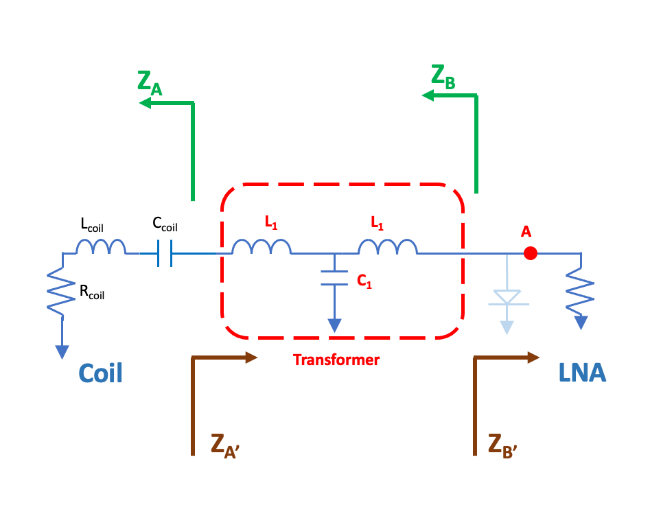
Figure 1. The schematic diagram of transforming the impedance between a coil to a low-noise pre-amplifier (LNA) using passive elements in a T-network topology.
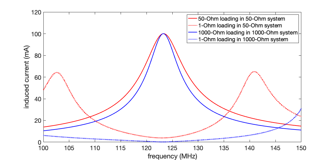
Figure 2. Simulated induced currents when connecting the coil to a pre-amplifier impedance with matched or low (1𝛀 ) impedance in 1000𝛀 (blue) and 50𝛀 (red) systems resonating at 123 MHz.
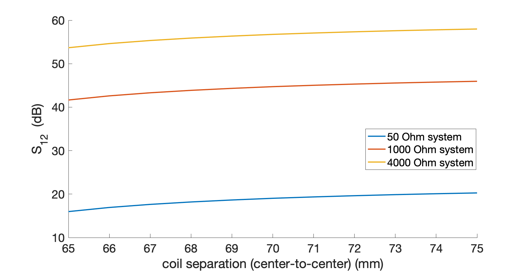
Figure 3. Simulated decoupling between two coils in 50𝛀, 1000𝛀 and 4000𝛀 systems
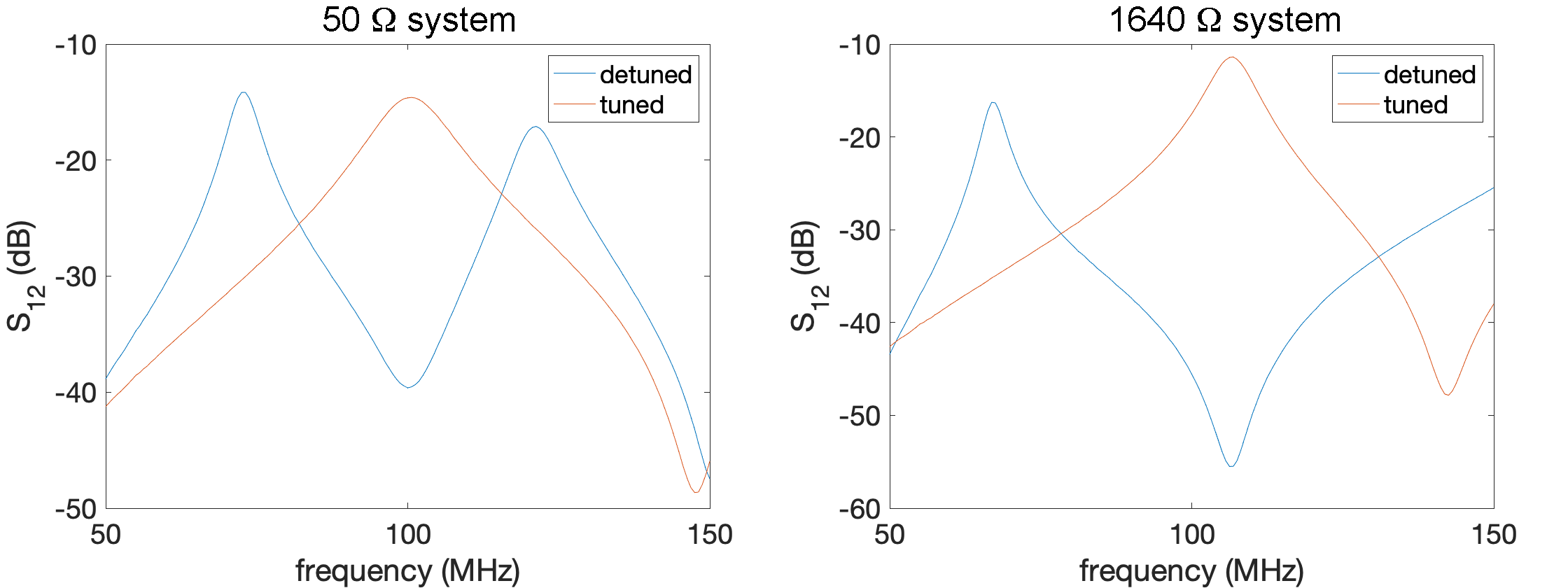
Figure 4. S12 measurements for tuned and detuned coil in 50𝛀 (left) and 1640𝛀 (right) systems.
DOI: https://doi.org/10.58530/2023/5071