5070
Reconfigurable Coaxial Receive Dipoles for Dynamic Parallel Imaging of Human Brain at 9.4T1High-field Magnetic Resonance, Max Planck Institute for Biological Cybernetics, Tuebingen, Germany, 2Electronical Workshop, Max Planck Institute for Biological Cybernetics, Tuebingen, Germany, 3Department for Biomedical Magnetic Resonance, University of Tübingen, Tuebingen, Germany
Synopsis
Keywords: RF Arrays & Systems, RF Arrays & Systems
Recently developed dynamic parallel imaging, i.e. rapid modulation of element's sensitivities during acquisition, greatly improved the performance of the method. In this work, sensitivity profiles of dipole elements were electronically reconfigured by varying impedances of lumped element circuits connected in series with the dipoles . This required a large number of DC wires directly connected to the dipoles. In the present work, we developed, constructed, and evaluated a dynamically reconfigurable 8-element coaxial dipole array for brain imaging at 9.4T. Our design eliminates the DC wires directly connected to the dipoles and, hence, substantially simplifies further increasing the number of receive channels.Introduction
Parallel imaging is an important MRI method that increases the acquisition speed(1). A standard benchmark for evaluation of the parallel imaging performance is a so-called g-factor(1). To minimize the g-factor value, a large number of receive coils with spatially diverse sensitivity is required. Recently, a novel method for improvement of parallel imaging without additional receive elements, i.e. dynamic switching of the individual coil's sensitivities during acquisition, has been developed(2,3). Firstly, a loop array with a variable in-plane sensitivity was presented(2). Following this line of research, an array of eight dipoles with modulated sensitivity profiles along the dipole length was developed (3). This design enabled an acceleration in the head-foot direction(3). Sensitivity profile of each dipole was electronically reconfigured by varying impedances of circuits placed in each arm of the dipole. This required 32 DC wires for an 8-element array prototype. Since dipoles are very sensitive to parallel conductors, further increasing the number of receive channels is very difficult using this design. E.g., current state-of-the-art receive arrays have 30 and above elements. In the present work, we developed, constructed, and evaluated a dynamically reconfigurable 8-channel coaxial dipole array for brain imaging at 9.4T. Our design eliminates the DC wires directly connected to the dipoles. It also reduces the inductance value required for current distribution manipulation.Methods
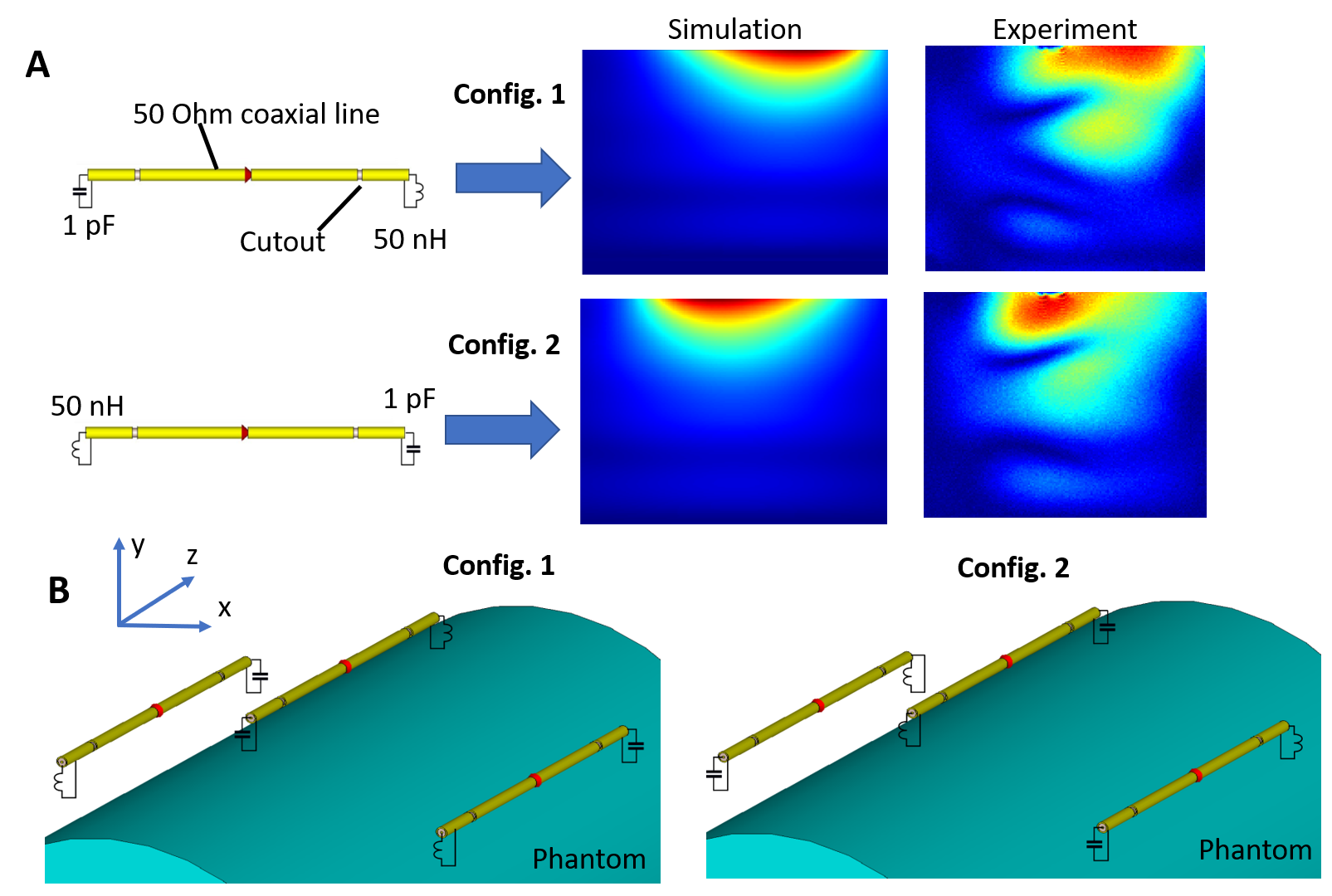
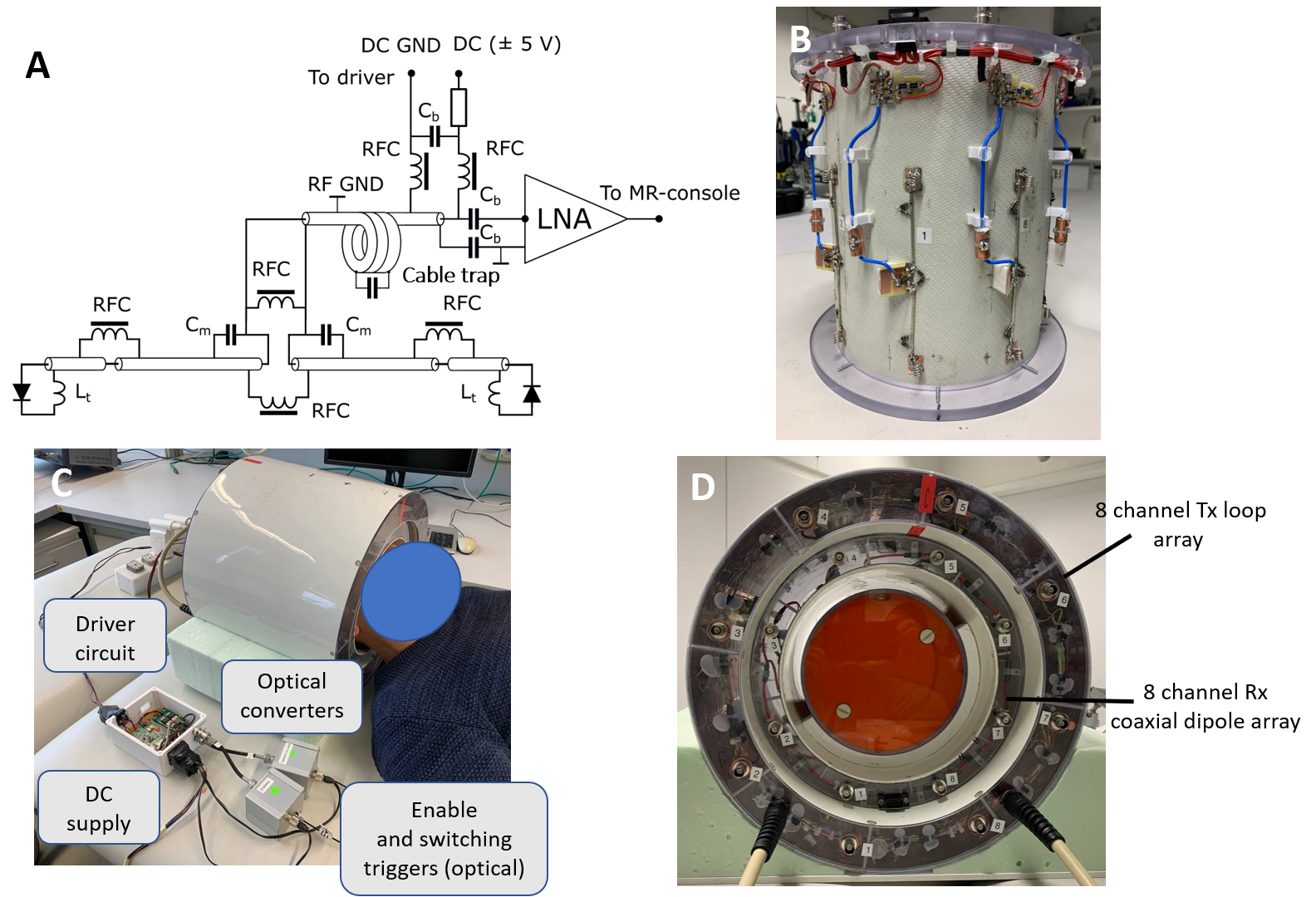
Use of coaxial dipoles in MRI was previously suggested in(4). Following this work, the reconfigurable coaxial dipole consisted of a 13-cm coaxial line with two gaps in the shield located at 2-cm distance from the ends (Fig 1A). In contrast to(4), in our design the shield and inner conductor were shorted at the driving port location. At both ends the core and shield were connected by lumped element circuits, impedance of which can be switched between inductive and capacitive. By connecting an inductor and capacitor to the opposite ends of the dipole (Fig.1A), two current distributions with its maximum shifted toward one or the other ends of the dipole are formed (Fig.1). Dynamic switching between these two states produces two virtual rows of elements. In the final array design, we placed dipoles in the so-called "chess order" as shown in Fig.1B, which allows an acceleration in the head-feet direction even for static configurations(3). Fig.2 shows the final schematic of the reconfigurable coaxial dipole element (Fig.2A), photos of the array (Fig.2B), and the entire set up (Figs.2C,D). For switching between the two states, PIN diodes were connected in series to inductors in opposite directions (Fig.2A). Thus, applying positive voltage, we produced a 50-nH inductor at one end and small capacitor (~1pF) at the other end. For the negative bias, we had the opposite configuration. With no voltage applied, the dipole was detuned. DC voltage was delivered through the RF cable (Fig.2B). The final set up consisted of the developed receive-only 8-element coaxial dipole array and 8-element transmit-only loop array (Figs.2C,D). Numerically simulated dipole sensitivity profiles (CST studio) were later combined in MatLab to calculate g-factors. Parallel receive performance was investigated both on a phantom and in-vivo. Sensitivity profiles were switched every 10µs for a strongly oversampled readout with a dwell time of 1µs. Retrospective SENSE reconstructions have been performed using coil sensitivity maps via ESPIRIT(5) from the central 48x48 k-space lines. All data were pre-whitened according to noise covariance obtained from a separate noise-only scan. Data was acquired on a Siemens 9.4T human MR-scanner with an RF and gradient spoiled GRE sequence (TR/TE=20ms/10ms, FA=20°, 200x200x60 matrix, FOV=220mmx220mmx120mm, 20% slice oversampling).Results and Discussion
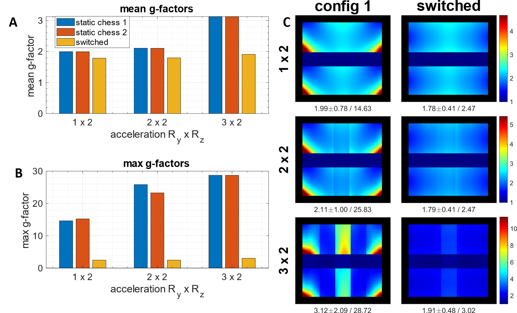
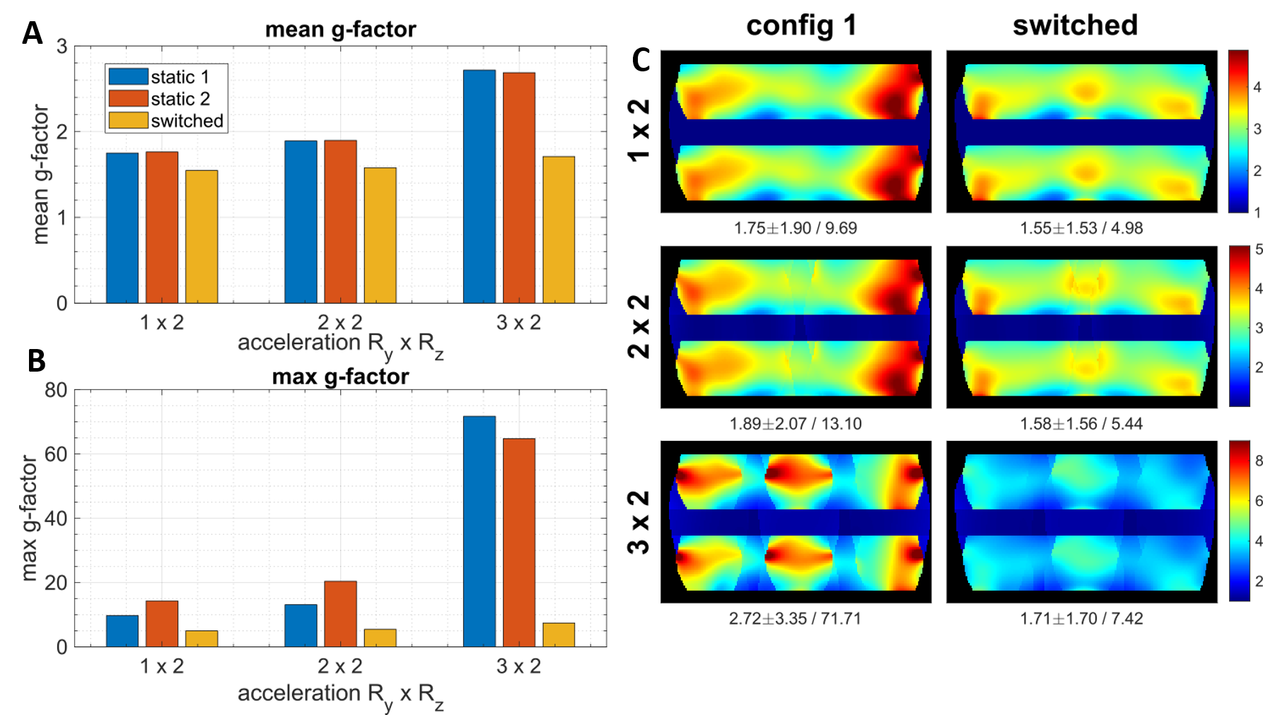
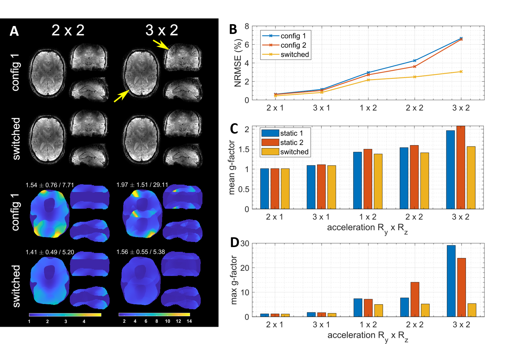
Figs.3 and 4 show numerically simulated (Fig.3) and experimentally measured (Fig.4) g-factor improvement due to switching of asymmetric dipole sensitivities as compared to static cases. Fig.5 shows in-vivo data. For example, in the case of RyxRz=2x2 acceleration, switching provides an 8% lower mean and 33% lower maximum g-factor in-vivo, and ~20% lower mean and ~2.5 times lower maximum g-factor for the phantom measurements. In all settings, i.e., simulation, phantom and in vivo measurements, rapid switching between the sensitivity profiles strongly reduces both mean and maximum g-factors compared to the conventional static cases. The absolute values of g-factors for a specific acceleration factor and the observed switching improvement varied between all of these settings due to various experimental conditions like FOV and object masking. In general, the idea behind the developed coaxial dipole design is similar to the previously reported common reconfigurable dipoles(3). However, the new design has the following benefits. Firstly, it eliminates the DC wires connected directly to the dipoles and provides an easy way of further increasing the number of receive elements in the array. In addition, it uses lower tuning inductances, i.e. 50nH vs 120nH(3). The proposed reconfigurable coaxial dipole elements can be also combined with loops to further minimize g-factors and improve central SNR(6).Conclusion
We developed, constructed, and evaluated a 8-element reconfigurable receive-only coaxial dipole array for dynamic parallel imaging of the brain at 9.4T. This novel design eliminates DC wires connected directly to the dipoles. It also substantially reduces the inductances in comparison to the previous design. Finally, dynamic switching provides 8% lower mean and 33% lower maximum g-factors (for the case of RyxRz=2x2 acceleration) in-vivo compared to the static case.Acknowledgements
Financial support of the ERC Advanced Grant “SpreadMRI”, No 834940 is gratefully acknowledged.References
1. Pruessmann, K. P., Weiger, M., Scheidegger, M. B., & Boesiger, P. (1999). SENSE: sensitivity encoding for fast MRI. Magnetic Resonance in Medicine, 42(5), 952-962.
2. Glang F, Nikulin AV, Bause J, et al. Accelerated MRI at 9.4 T with electronically modulated time-varying receive sensitivities. Magnetic Resonance in Medicine 2022;88:742–756
3. Anton V. Nikulin, Felix Glang, Nikolai Avdievich, Dario Bosch, Theodor Steffen and Klaus Scheffler (2022). Dynamic Radiofrequency Coils to Accelerate Parallel Imaging at Ultra-High Magnetic Field IEEE. Transactions on Medical Imaging (in revision)
4. van Leeuwen, C. C., Steensma, B. R., Klomp, D. W., van den Berg, C. A., & Raaijmakers, A. J. (2022). The Coax Dipole: A fully flexible coaxial cable dipole antenna with flattened current distribution for body imaging at 7 Tesla. Magnetic Resonance in Medicine, 87(1), 528-540.
5. Uecker M, Lai P, Murphy MJ, et al. ESPIRiT—an eigenvalue approach to autocalibrating parallel MRI: Where SENSE meets GRAPPA. Magnetic Resonance in Medicine 2014;71:990–1001
6. Avdievich NI, Nikulin AV, Ruhm L, Magill AW, Henning A, Scheffler K. Double-Row Dipole/Loop Combined Array for Human Whole Brain Imaging at 7 T. NMR in BioMed 2022, 35 (10), e4773.
Figures