5069
A Low-complexity Approach to Decouple Dual-tuned RF Coil Elements in Multinuclear Receive Array Coils1Department of Electrical and Computer Engineering, Texas A&M University, College Station, TX, United States
Synopsis
Keywords: RF Arrays & Systems, RF Arrays & Systems, Multi-Nuclei, multinuclear, decoupling
This study proposes a novel low-complexity decoupling approach for multi-nuclei receive array coil design. Instead of using narrowband LC networks and isolation preamplifiers, a preamplifier with high input impedance can be used to decouple receive coils while maintaining most SNR. A broadband impedance matching network consist of LCC multi-tuned circuit and transformer was developed to interface the coil with a high Z preamplifier. The proposed setup has achieved more than 15dB of decoupling over a range of 25MHz. The prototype simultaneously yielded 73.6% and 91.9% of SNR at 2H and 23Na when compared to the conventional single-tuned preamplifier decoupling methods.Introduction
MRI phased array coils provide many advantages, such as SNR optimization and scan time acceleration. Using the preamplifier decoupling method proposed by Roemer et. al.1, phased array coils with massive channel counts have been developed for proton2,3. An emerging application of MRI array coils is multi-nuclei imaging. So far, most multi-nuclei array coils have been developed by nesting multiple layers of single-tuned array coils and associated preamplifier decoupling circuits into one array4,5. These studies have successfully demonstrated the feasibility of multi-nuclei arrays. However, the complexity of these designs may limit the further development of multi-nuclei array coil to include a greater number of nuclei and higher channel count. In this work, we report a novel low-complexity decoupling configuration that allows the receive array coil to be operated/decoupled at multiple frequencies using only one set of high impedance LNAs.Methods
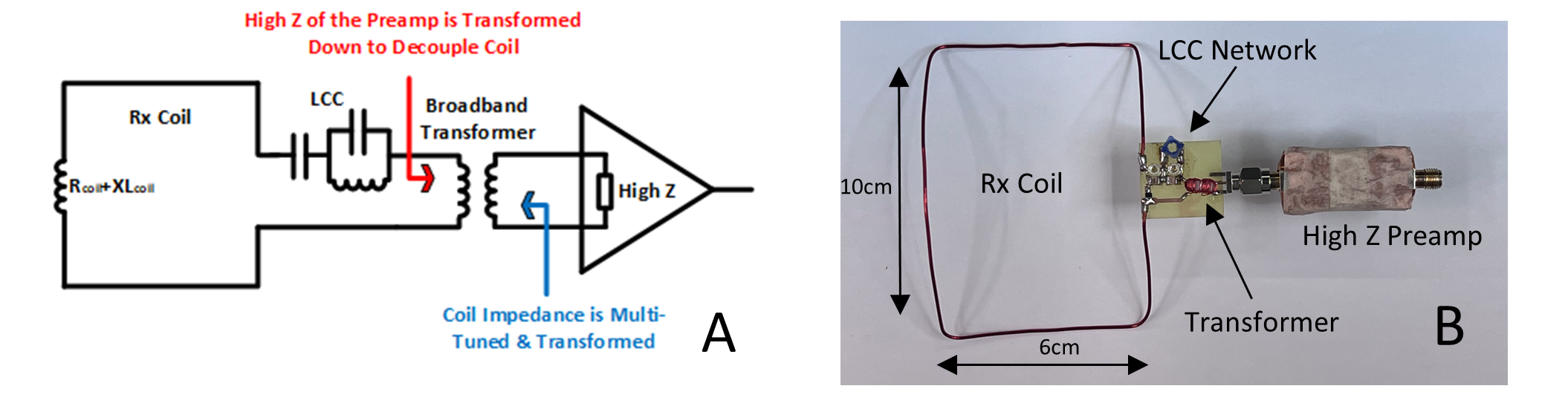
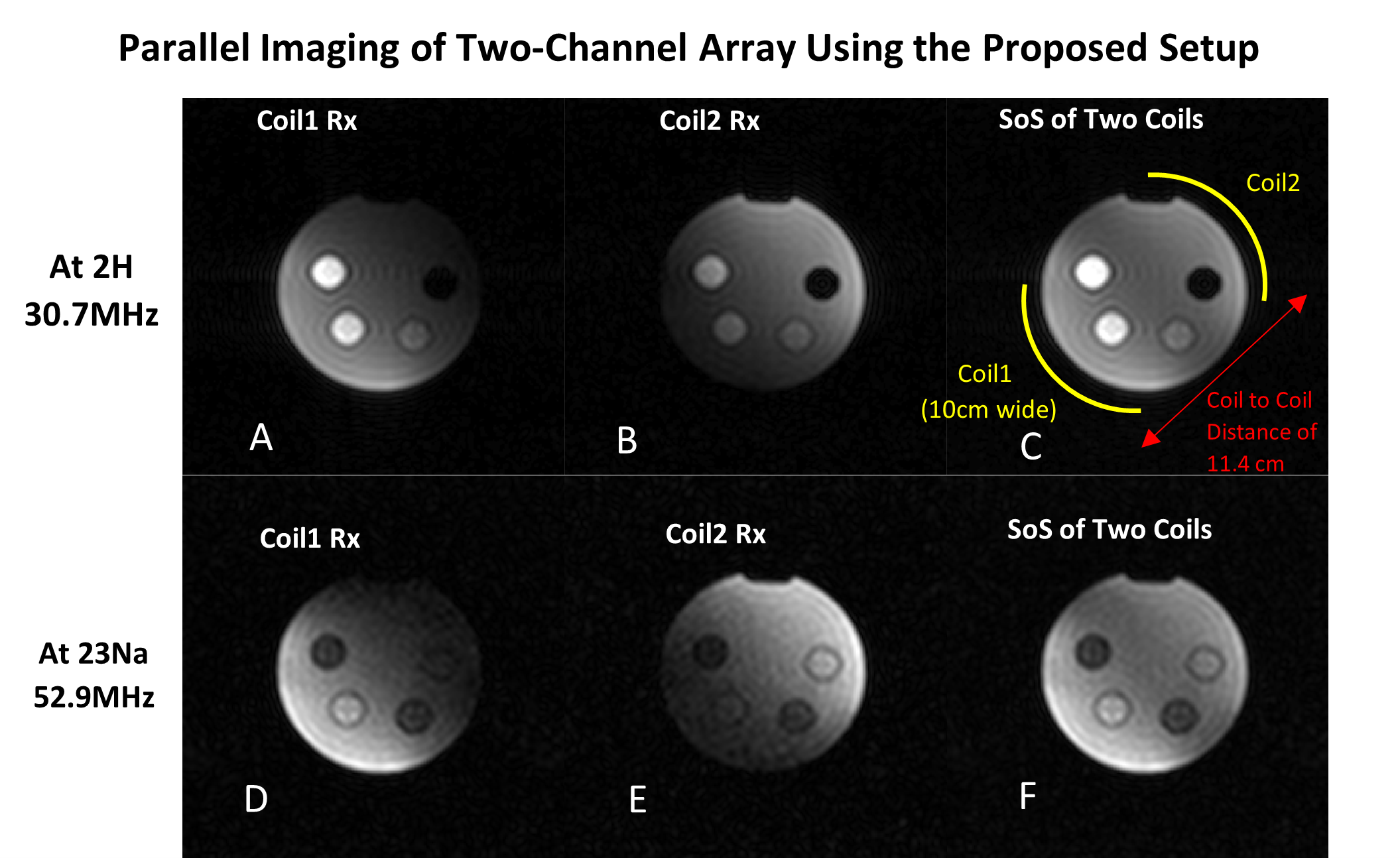
Figure 1 shows the schematic of the decoupling configuration developed in this study. Instead of creating high decoupling impedance using LC matching network and isolation preamplifiers [1], the high input impedance of the preamplifier (such as operational amplifier LMH6629 or RF LNA elcry1-u) can be used to decouple the Rx coil directly. The coil (10x6cm square loop conformed around an 11.4 diameter acrylic cylinder) is first multi-series-tuned using an LCC network (designed for Larmor frequencies of 2H/30.7MHz and 23Na/52.9MHz at 4.7T), and then up-transformed close to the optimal NF matching points of the preamplifier through a house-built transformer (primary and secondary windings wrapped around a #6-32 nylon nut). The high input impedance of the preamplifier, though down-transformed, appears in series with the Rx coil suppressing the RF currents induced by cross-talk from other elements. Since both the high input impedance of a preamplifier and the impedance ratio of a transformer is theoretically independent on the frequency, this proposed configuration can thus operate in a wider frequency manner when comparing to the narrow bandwidth of a conventional LC parallel-resonant match and decoupling network. Realistically, the parasitic parameters still play an important role in limiting the frequency band. A pair of self-decoupled sniffing probes with a VNA on S21 mode were first used to characterize the decoupling performance of the proposed setup on bench at frequencies corresponding to 2H and 23Na at 4.7 Tesla. Two additional surface coils using the conventional preamplifier decoupling method (WanTcom WMM31P and WMM50P) were used to compare the imaging SNR with the proposed setup. Finally, an array of two coils with the proposed setup were placed around a jar phantom with a distance of 11.4cm (geometrically coupled) to examine the decoupling performance in paralleling imaging.Results
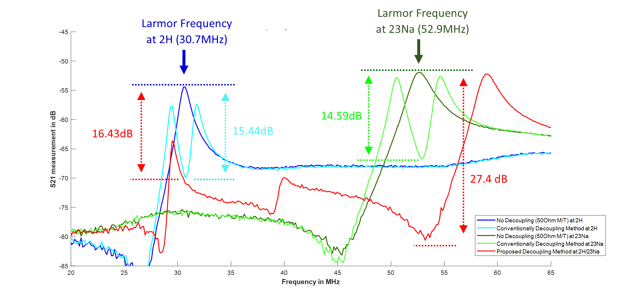
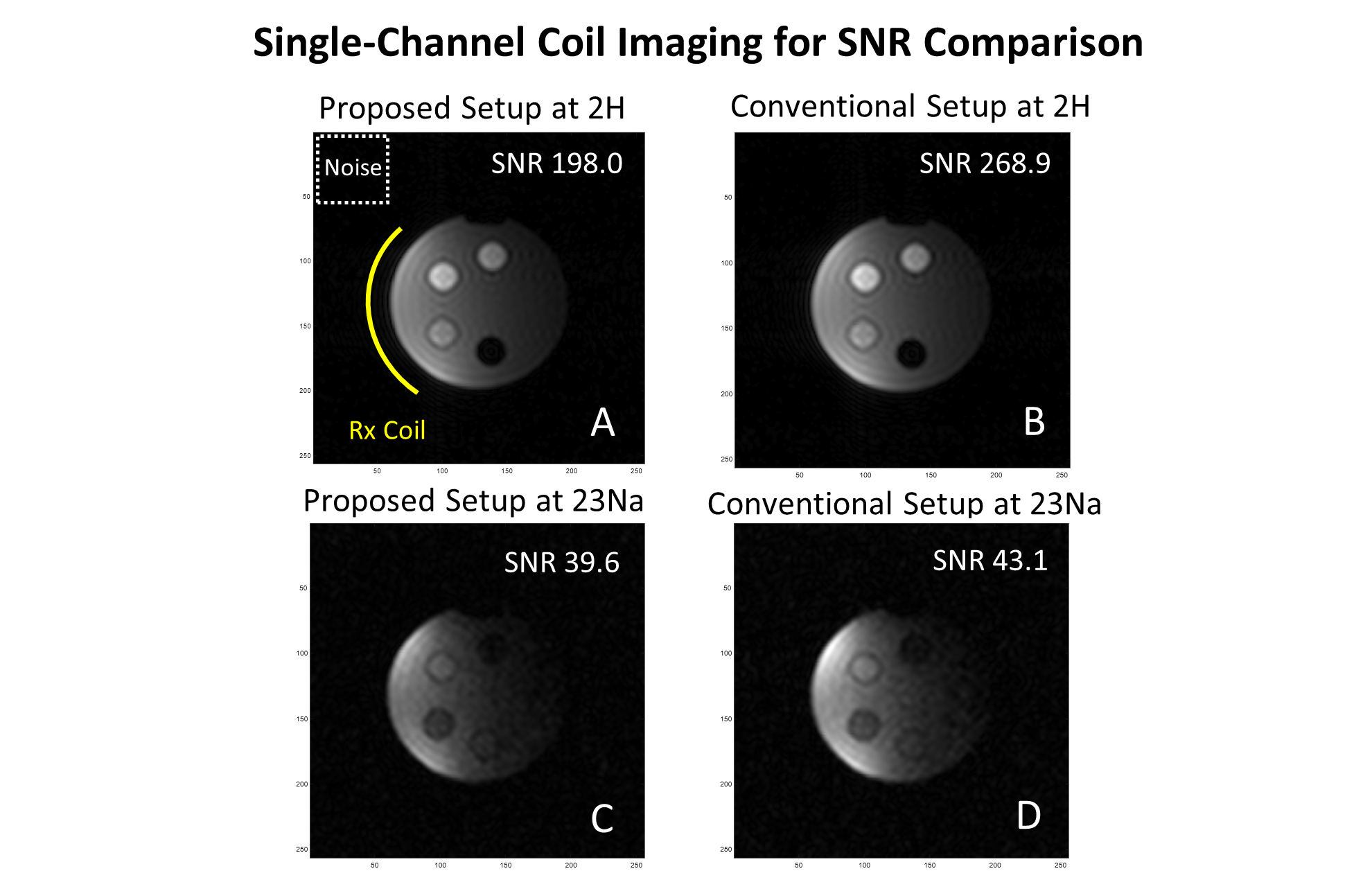
Figure 2 shows the bench measured decoupling performance of the proposed setup compared to the conventional method, which was separately optimized at both 2H and 23Na. With conventional method, the LC network and isolation preamplifier can provide about 16.43dB (at 2H) and 14.59dB (at 23Na) of decoupling calculated based on the S21 down from the 50Ω M/T case. The proposed setup, with the help of high-Z preamplifier and transformer, can generate more than 15dB of decoupling for about 25MHz covering both Larmor frequencies of 2H and 23Na. Figure 3 shows the single channel coil Rx imaging acquired using the proposed setup as well as the reference conventional setup at both 2H and 23Na. The two single-tuned reference setups can provide SNR of 268.9 and 43.1, at the Larmor frequency of 2H and 23Na, individually. The proposed setup can provide SNR of 198.0 and 39.6 at 2H and 23Na, without changing hardware. Figure 4 shows imaging results acquired using the two-coil array with the testing setup, at both 2H and 23Na. The single coil Rx images and the sum of square images are shown for both 2H and 23Na cases. With the help of additional 16dB/27dB decoupling added by the proposed setup, no significant coupling pattern is observed with the current configuration of two coils geometrically coupled.Discussions and Conclusions
In this work, a novel decoupling configuration for multi-nuclei Rx array coil design is developed. Compared to the conventional preamplifier decoupling method, in which decoupling is only achieved at one frequency, the proposed configuration can provide reasonable coil decoupling over a wide range, 25 MHz in this study. At the Larmor frequencies of 2H and 23Na, the proposed setup can yield about 73.6% and 91.9% of SNR respectively when compared to the conventional setups using separate isolation preamplifiers. This sensitivity cost, while not ideal, is comparable to the expected 25 to 30% of SNR loss expected from conventional dual-tuned networks when compared to single-tuned coils6. The proposed setup offers the advantage of simultaneous multinuclear operation with a single array. The performance of this setup can be further improved if a better non-ferrite transformer can be realized. In this study, the bandwidth or the impedance ratio of this prototype transformer was found difficult to be improved without sacrificing the other parameters. Future work will focus on minimizing the parasitic parameter of the transformer and expanding its bandwidth and impedance ratio.Acknowledgements
Support from the National Institutes of Health through grant 5 R21 EB028516-02 is gratefully acknowledged.References
1. Roemer PB, Edelstein WA, Hayes CE, Souza SP, Mueller OM. The NMR phased array. Magnetic resonance in medicine. 1990;16(2):192-225.
2. Gruber B, Stockmann JP, Keil B, Ghotra A, Feinberg DA, Wald LL. A 128-channel head coil array for cortical imaging at 7 Tesla. Paper presented at: 2021 International Conference on Electromagnetics in Advanced Applications (ICEAA)2021.
3. Schmitt M, Potthast A, Sosnovik DE, et al. A 128-channel receive-only cardiac coil for highly accelerated cardiac MRI at 3 Tesla. Magn Reson Med. 2008;59(6):1431-1439.
4. Brown R, Lakshmanan K, Madelin G, Parasoglou P. A nested phosphorus and proton coil array for brain magnetic resonance imaging and spectroscopy. Neuroimage. 2016;124(Pt A):602-611.
5. Lakshmanan K, Brown R, Madelin G, Qian Y, Boada F, Wiggins GC. An eight-channel sodium/proton coil for brain MRI at 3 T. NMR Biomed. 2018;31(2).
6. Choi CH, Hong SM, Felder J, Shah NJ. The state-of-the-art and emerging design approaches of double-tuned RF coils for X-nuclei, brain MR imaging and spectroscopy: A review. Magn Reson Imaging. 2020;72:103-116.
Figures