5067
Investigating Dipole Antennas as 1H Transmit Elements for a 1H/31P Calf Coil at 7 T1Division MR Physics, Center for Medical Physics and Biomedical Engineering, Medical University of Vienna, Vienna, Austria
Synopsis
Keywords: RF Arrays & Systems, RF Arrays & Systems, dipoles, simulation
Different dipole antenna types as 1H transmit elements for metabolic 1H/31P MRS studies of the human calf were investigated. In simulations, the dipole elements and a loop coil were compared in terms of transmit efficiency and SAR. A three-element array of the best-performing design was simulated and constructed, and its transmit performance was found to be comparable to a four-element loop array. Investigating the interaction between a dipole transmit element and a receive-only loop placed underneath, efficient geometric decoupling was observed. This can be exploited to improve the receive sensitivity (homogeneity, depth) by using transceiver dipoles together with receive-only loops.Introduction
Interleaved Phosphorous-31 (31P) and Hydrogen (1H) magnetic resonance spectroscopy (MRS) allows simultaneous quantification of lactate and high energy metabolites in skeletal muscle such as the human calf1. For improving on this application, we will develop a half-cylinder-shaped calf coil with separate transmit (Tx) and receive (Rx) arrays for 1H and a 31P transceive (TxRx) array operating at 7 T. Unlike previous calf coils2 where the 1H part was mainly used for localization and B0-shimming, we target superior 1H performance to facilitate 1H MRS measurements.Over the last years, dipole antennas have been explored as Tx elements for torso and brain imaging at ultra-high field due to their improved penetration depth and homogeneous excitation compared to loop resonators3,4. Here we investigate the efficiency of dipoles as 1H transmitters for the calf region in the context of metabolic 1H/31P MRS studies.
Methods
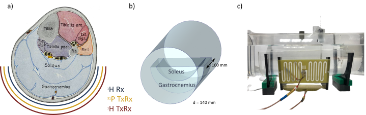
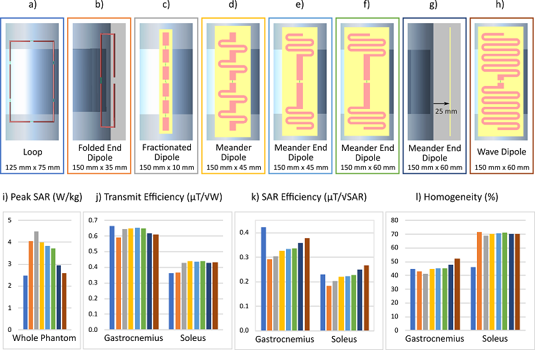
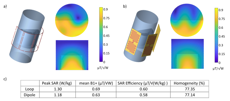
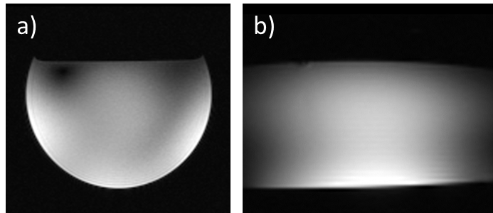
An array of dipole antennas would constitute the outermost layer of the envisioned, nested 1H/31P calf coil design (Fig. 1a) for data acquisition from gastrocnemius and soleus muscles. Considering the spatial confines defined by this set-up, i.e. coil positioning below the knee and compatibility with an ergometer for plantar-flexion exercise, three dipole types (150 mm physical length) based on literature3,4 (Fig. 2b,c,d) and a loop resonator (Fig. 2a) based on a previous calf coil design5 were modelled and compared using 3D electromagnetic simulation and co-simulation6,7. Post-processing and analysis were performed in Matlab using an in-house toolbox based on the quadratic form power correlation matrix formalism8,9. The geometry and sample distance of the best performing dipole was optimized in four iterations (Fig. 2e-h). Evaluation criteria were the transmit efficiency (mean(B1+)/sqrt(input power)), SAR efficiency (transmit efficiency/sqrt(SAR10g,peak)) and homogeneity (1-std(B1+)/mean(B1+)), which were calculated for the two regions of interest (ROIs) shown in Fig. 1b.A three-element array of the optimized dipole design was simulated and fabricated to be compared to a four-element loop array based on a previous calf coil design by our group5. The loop array was driven with a phase shift of (0°, 70°, 140°, 210°)5. In simulation, the phase shift for the dipole array was optimized in 10° steps to maximize SAR efficiency and field homogeneity. B1+ field maps were simulated for both arrays and compared numerically for the two regions of interest. For experimental evaluation, the phase shifts were implemented via corresponding cable lengths after a 3-way Wilkinson power splitter and three transmit-receive switches. A first test image with the dipole array in TxRx mode was acquired on a 7 T MRI (Magnetom, Siemens Healthineers, Erlangen, Germany) to validate the viability of this setup.
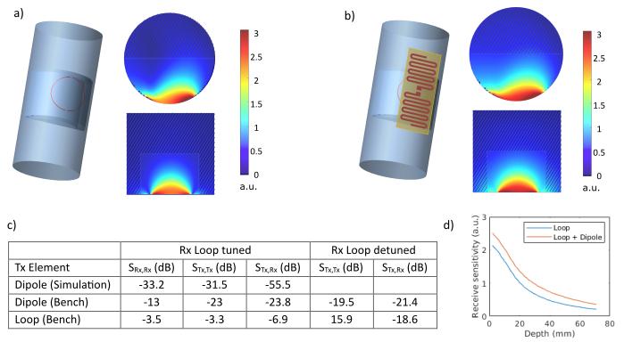
In view of using the dipoles in TxRx-mode, i.e., also for reception in addition to the planned 1H Rx-only loop array (Fig. 1a) as suggested for a cardiac dipole array9, the interaction between a single dipole element (Fig. 2h) and a 7 cm Rx-only loop was studied in simulation and on the bench and compared to a similar setup with a loop TxRx coil (Fig. 2a). In simulations, receive sensitivity maps7 were calculated for a dipole with a receive loop underneath and compared to the receive loop alone. For bench measurements, a classical trap circuit with PIN diode switch for active detuning was implemented in the Rx-only loop.
Results
All investigated single element coils were matched to -22 dB or better in co-simulation. The meander dipole showed the highest simulated SAR efficiency out of the three initial dipole types (Fig. 2b,c,d) and was thus optimized further, resulting in the wave dipole design (Fig. 2h). The simulated B1+ results for a three-element array of this dipole are summarized in Fig. 3 and visually and numerically compared to a four-element loop array. Reflection/transmission S-parameters were below -34/-11 dB in simulation and below -24/-11 dB on the bench, respectively. First MR images acquired with the dipole array can be seen in Fig. 4.Fig. 5a,b shows simulated maps of the receive sensitivity for a TxRx dipole together with an Rx loop, and for the Rx loop alone. Across the two ROIs (Fig. 1b), the combined receive sensitivity of dipole and loop is 42 % higher than that of the Rx loop alone. The dipole can be combined with the Rx loop for reception thanks to efficient geometric decoupling between these two coils, which is demonstrated by simulated and measured S-parameters in Fig. 5c. In contrast, measuring S-parameters of the receive-only loop underneath a Tx loop showed extensive coupling, see Fig. 5c, with strong resonance peak splitting for both elements.
Discussion and Conclusion
The three-element dipole array shows comparable 1H Tx performance to the four-element loop array for the combined gastrocnemius and soleus ROI. The low mutual coupling between the dipole and Rx loop offers not only the possibility to utilize the dipole as additional Rx element but may also be beneficial for limiting the interaction with 31P array, which will be added later.Besides assembling the envisioned 1H/31P calf coil, future work will comprise B1+ mapping for a quantitative comparison with simulation and potentially studies on mutual dipole decoupling to enable a four-element dipole array for the calf.
Acknowledgements
We thank Deniz Celebi and Tim Hebenstreit (both MedUni Vienna) for their contribution.
This project was funded by the Austrian Science Fund (FWF) project no. P35305-B.
References
1) Meyerspeer M, Kemp GJ, Mlynarik V, Krssak M, Szendroedi J, Nowotny P, Roden M, Moser E. Direct noninvasive quantification of lactate and high energy phosphates simultaneously in exercising human skeletal muscle by localized magnetic resonance spectroscopy. Magnetic Resonance in Medicine, 2007;57(4):654–660. https://doi.org/10.1002/mrm.21188
2) Goluch S, Kuehne A, Meyerspeer M, Kriegl R, Schmid AI, Herrmann T, Mallow J, Hong SM, Cho ZH, Bernading J, Moser E, Laistler E, A form-fitted three channel 31P, two channel 1H transceive coil array for calf muscle studies at 7 T. Magnetic Resonance in Medicine, 2015; 73(6):2376–2389. https://doi.org/10.1002/mrm.25339
3) Raaijmakers AJ, Italiaander M, Voogt IJ, Luijten PR, Hoogduin JM, Klomp DW, van den Berg CA, The fractionated dipole antenna: A new antenna for body imaging at 7 Tesla. Magnetic Resonance in Medicine, 2016; 75(3):1366-1374. https://doi.org/10.1002/mrm.25596
4) Avdievich NI, Solomakha G, Ruhm L, Nikulin AV, Magill AW, Scheffler K. Folded-end dipole transceiver array for human whole-brain imaging at 7 T. NMR in Biomedicine. 2021; 34:e4541. https://doi.org/10.1002/nbm.4541
5) Goluch S, Frass-Kriegl R, Meyerspeer M, Pichler M, Sieg J, Gajdosik M, Krssak M, Laistler E. Proton-decoupled carbon magnetic resonance spectroscopy in human calf muscles at 7 T using a multi-channel radiofrequency coil. Scientific Reports, 2018 Apr 18;8(1):6211. https://doi.org/10.1038/s41598-018-24423-x
6) Kozlov M, Turner R. Fast MRI coil analysis based on 3-D electromagnetic and RF circuit co-simulation. Journal of magnetic resonance, 2009; 200(1):147-52. https://doi.org/10.1016/j.jmr.2009.06.005
7) Lemdiasov RA, Obi AA, Ludwig R. A numerical postprocessing procedure for analyzing radio frequency MRI coils. Concepts Magn. Reson., 2011; 38A:133-147. https://doi.org/10.1002/cmr.a.20217
8) Kuehne A, Goluch S, Waxmann P, Seifert F, Ittermann B, Moser E and Laistler E. Power balance and loss mechanism analysis in RF transmit coil arrays. Magnetic Resonance in Medicine, 2015; 74(4): 1165-1176. https://doi.org/10.1002/mrm.25493
9) Steensma BR, Voogt IJ, Leiner T, Luijten PR, Habets J, Klomp DWJ, van den Berg CAT, Raaijmakers AJE. An 8-channel Tx/Rx dipole array combined with 16 Rx loops for high-resolution functional cardiac imaging at 7 T. Magnetic Resonance Materials in Physics, Biology and Medicine. 2018 Feb;31(1):7-18. https://doi.org/10.1007/s10334-017-0665-5
Figures