4598
Multi-Continent Analysis of Geometric Distortion in Low-Field MRI1Magnetic Imaging Group, National Institute of Standards and Technology, Boulder, CO, United States, 2Department of Physics, University of Colorado Boulder, Boulder, CO, United States, 3Department of Neurology and the Center for Genomic Medicine, Massachusetts General Hospital and Harvard Medical School, Boston, MA, United States, 4Mathematical Analysis and Modeling Group, National Institute of Standards and Technology, Boulder, CO, United States, 5A. A. Martinos Center for Biomedical Imaging, Massachusetts General Hospital, Charlestown, MA, United States, 6Department of Neurosurgery, Yale University School of Medicine, New Haven, CT, United States, 7CURE Children's Hospital of Uganda, Mbale, Uganda, 8Faculty of Applied Sciences and Technology, Mbarara University of Science and Technology, Mbarara, Uganda, 9Hyperfine, Inc., Guilford, CT, United States
Synopsis
Keywords: Artifacts, Low-Field MRI
The assessment of brain morphology requires geometric accuracy, and the monitoring of pathologies like dementia requires geometric stability over time and between systems. We aim to assess the geometric accuracy and stability of a head-only 64 mT system by imaging the cylindrical phantom provided by the manufacturer, positioned with a 3D-printed holder for stability, and analyzing the geometric fidelity of the images produced by a variety of product sequences. The initial assessment examines the perimeter of the phantom and how it varies along the S-I direction.Introduction
Assessment of brain morphology is useful in monitoring of pathologies like dementia. Such measurements require geometric accuracy and stability over time and between systems. The introduction of low-field, portable MRI systems has increased the accessibility of brain MRI, making them potentially useful in management of these diseases. Geometric distortions are a known phenomenon in MRI1, highlighting the need for robust characterization to enable comparisons across time and field strength.We aim to assess geometric accuracy and stability of a 64mT portable system (Hyperfine Inc., Guilford, CT). This is accomplished through creation of a standard holder for the system’s QA phantom and an analysis method applied to product sequences. This setup was analyzed across five systems at three sites to assess geometric fidelity.
Methods
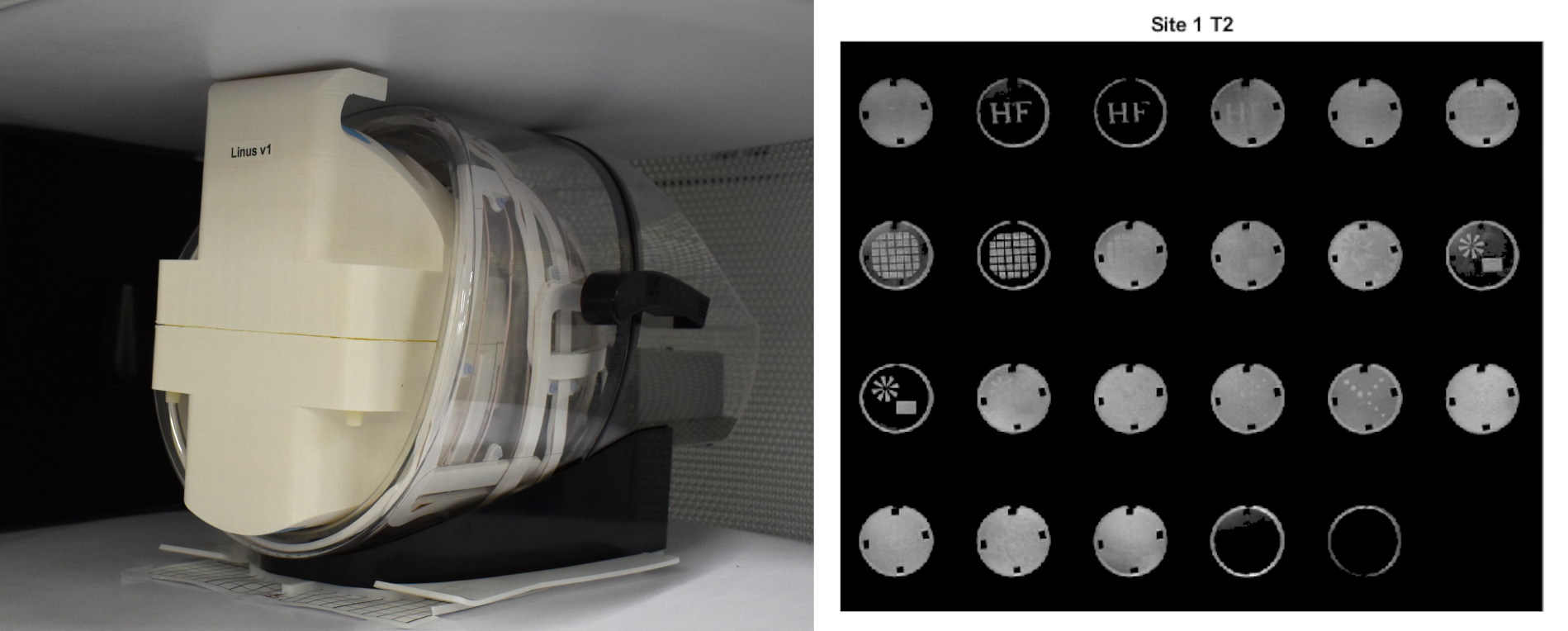
To maximize the consistency of phantom positioning across sites, a 3D-printed holder (Figure 1) was developed to repeatably position the cylindrical phantom in the center of the head coil. Standard axial T1-weighted, T2-weighted, and ADC sequences were used. For analysis, only the b=0 image from the ADC protocol was used.Images were acquired at three sites: two in North America and one in Africa. Site 1’s system was hardware 1.8 running software rc8.5.0; site 2 has three systems, two hardware 1.6 and one 1.9 running rc8.6.0 (Site 2c). One site 2 system (Site 2a) ran rc8.5.0, while the other (Site 2b) was tested before and after upgrading from software 8.3.0 to 8.4.0. Site 3’s system was hardware 1.7, software 8.4.0.
Distortion was analyzed by fitting an ellipse to the outer perimeter of each axial slice of the phantom, corresponding to the inner diameter of the cylindrical phantom. The ellipse was fit using an iterative least-squares approach with 5 key parameters: (x,y) position of center; semi-major axis length $$$a$$$; semi-minor axis length $$$b$$$; and angle of major axis $$$\theta$$$2-4. After fitting, data that corresponded to partial slices at the ends of the phantom were removed. For all images, voxel dimensions and slice positions were based on data reported by the scanner.
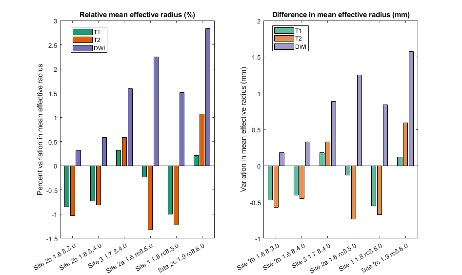
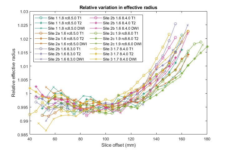
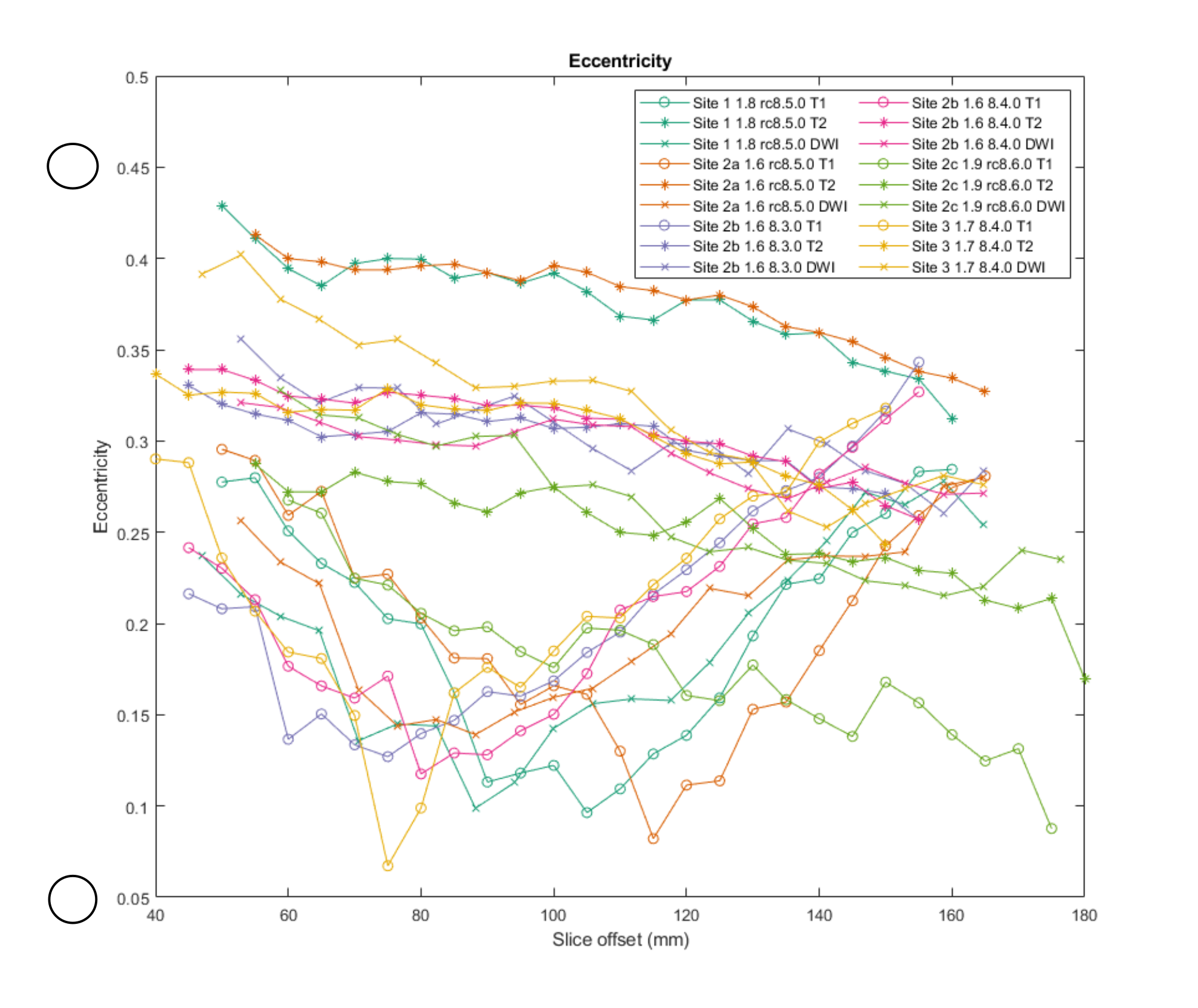
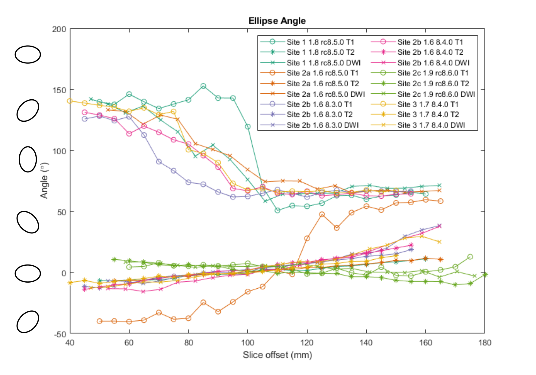
Three metrics were chosen to evaluate geometric distortion: effective radius of the ellipse $$$r_{eff}=ab$$$, eccentricity $$$e=\sqrt(1-b^2/a^2)$$$ , and semi-major axis angle . The mean effective radius was compared to the known inner radius of the coil as a metric of areal distortion (Figure 2), and the relative effective radius for each slice was computed relative to its mean effective radius (Figure 3). Eccentricity (Figure 4) gives an indication of shape distortion, and axis angle (Figure 5) shows how consistent distortion is across slices.
Results
Analyzing the mean effective radii in Figure 2, the amount of areal distortion at 64mT averaged 1.03% (0.57mm). The diffusion-weighted scan, with a different nominal resolution, consistently had a higher mean effective radius than the other scans. Analyzing relative effective radii in Figure 3, we see that there is very little variation between scans.Assessing eccentricity (Figure 4), we see more variation. The T2 sequence generally appears to have the highest eccentricity while diffusion generally has the lowest, except for Site 3, which has the highest eccentricity on DWI. Examining ellipse angle (Figure 5), all the T2 scans have very similar behavior, while T1 and DWI show more variation.
Discussion
Overall, we can see that the tested scanners have very small errors in effective radius and little areal distortion between slices. Some images have a significant amount of eccentricity, with T2 sequences at Site 1 and Site 2 (rc8.5.0) having the highest eccentricity. The eccentricity can vary from 0.067 to 0.318, and ellipse angle can vary by up to 102° across slices within a single scan.Looking at different software versions, the distortion on the same scanner is similar before and after a software upgrade from 8.3.0 to 8.4.0, with a maximum change in slice eccentricity of .044 and a median change of .012. The eccentricity is highest for the two scanners on software version rc8.5.0, and areal distortion is highest for scanners running rc8.5.0 and rc8.6.0; however, we were unable to compare to other software releases on the same scanners, so we cannot conclude if this is software or system dependent.
A potential source of error is tilt of the cylindrical phantom. The 3D-printed phantom holder was designed to minimize this error, but a small tilt could create small z-invariant 0th- or 1st-order shifts in ellipse parameters.
This assessment is limited to a relatively small volume: a cylinder approximately 120mm long and 111mm in diameter—much smaller than 154x200mm, the median male head cross-section5. Now that we have methodology and metrics of assessment, a new phantom could be developed to allow assessment over a larger field-of-view with internal structure to allow for assessing distortion within each slice.
Conclusion
The 64mT scanners have a low amount of areal distortion, but some sequences do have distortion of the image shape. Understanding the nature and magnitude of image distortion is crucial for assessing morphology across sites and systems. This work serves as a first step in understanding distortion on this new generation of low-field scanners. This work serves as a first step in understanding distortion on this new generation of low-field scanners that are able to easily be deployed across continents.Acknowledgements
Certain commercial equipment, instruments, or materials are identified in this paper in order to specify the experimental procedure adequately. Such identification is not intended to imply recommendation or endorsement by NIST, nor is it intended to imply that the materials or equipment identified are necessarily the best available for the purpose.
S.E.O. would like to acknowledge support from NIST-PREP (Professional Research Experience Program), performed under the following financial assistance award 70NANB18H006 from U.S. Department of Commerce, National Institute of Standards and Technology.
S.S. and J.O. would like to acknowledge support by NIH Grant 2R01HD085853
References
1Gunter, Jeffrey L., Matt A. Bernstein, Brett J. Borowski, Chadwick P. Ward, Paula J. Britson, Joel P. Felmlee, Norbert Schuff, Michael Weiner, and Clifford R. Jack. "Measurement of MRI scanner performance with the ADNI phantom." Medical physics 36, no. 6Part1 (2009): 2193-2205.
2Fitzgibbon, A. W., Pilu, M and Fischer, R. B., “Direct least squares fitting of ellipses”. Technical Report DAIRP-794, Department of Artificial Intelligence, The University of Edinburgh, January 1996
3Halir R., Flusser J. “Numerically Stable Direct Least Squares Fitting of Ellipses”, Proceedings of the 6th International Conference in Central Europe on Computer Graphics and Visualization, (WSCG, Plzen, Czech Republic), pp 125-132.
4Walter Gander, Gene H. Golub, Rolf Strebel, “Least-Squares Fitting of Circles and Ellipses”, BIT 34 (1994), 558-578.
5Gordon, C.C., Blackwell, C.L., Bradtmiller, B., Parham, J.L., Barrientos, P., Paquette, S.P., Corner, B.D., Carson, J.M., Venezia, J.C., Rockwell, B.M., Mucher, M., and Kristensen, S., 2015, “2012 Anthropometric Survey of U.S. Army Personnel: Methods and Summary Statistics.” Report No. NATICK/TR-15/007.
Figures