4593
Design and Test of a Flexible Two-row CTL Array and Its Detunable Resonant Elements for 10.5T MR Imaging1Department of Biomedical Engineering, State University of New York at Buffalo, Buffalo, NY, United States, 2Radiology, University of Minnesota, Minneapolis, MN, United States
Synopsis
Keywords: New Devices, High-Field MRI
A flexible patch array using small-sized 5-cm coaxial transmission line (CTL) resonators is designed, constructed and tested, aiming for human head imaging at the ultrahigh field of 10.5T. Bench tests on decoupling performance among resonant elements are shown. For full utility, a detuning circuit is successfully developed, showing the ecellent detuning capability for 5-cm small CTL loops at 447 MHz. This study suggests that it is possible to build high-density receive-only coil arrays using small-sized CTL resonators at 10.5T.Introduction
Massive RF arrays with closely placed small resonant elements are needed in high field MR to gain peripheral sensitivity and optimize parallel imaging performance. A challenge in designing such arrays is to achieve sufficient electromagnetic (EM) decoupling among the resonant elements. In the ultrahigh field regime, e.g 10.5T, with the increase in frequency, this problem becomes more pronounced due to increased radiation contributions. Recent studies show that the high impedance mode of coaxial transmission line (CTL) resonators possesses unique decoupling performance in relatively large loop arrays [1-3]. It is known since Roemer et al. [4] that higher impedance can limit the currents in the circuit and thus suppress EM coupling among resonant elements [5-7]. However, when the coil size is reduced, the impedance of the circuit decreases, leading to the augmented electromagnetic coupling among resonant elements. The high decoupling advantage of CTL resonators may thus vanish. In this work, we design and test an 8-channel flexible patch array consisting of two rows of small 5-cm diameter CTL resonators for human imaging at 447MHz, the proton Larmor frequency at the ultrahigh field of 10.5T. We investigate the decoupling behavior of both resonance modes and the coil efficiency. We also explore active detuning circuitry for the CTL resonators and evaluate the potential of using small-diameter CTL resonators for high-density receive-only array applications at 10.5T.Method
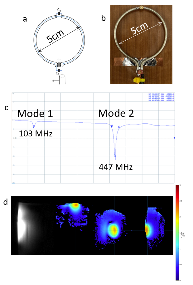
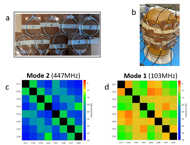
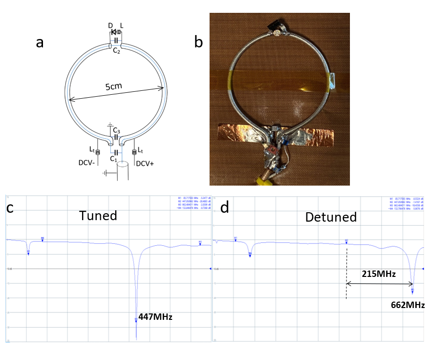
The 5-cm CTL resonators of the 447MHz flexible patch array are built using a 50-Ohm semi-rigid coaxial transmission line (UT-85C-FORM, Micro-Coax, Pottstown, PA) which offers low-loss and reasonable flexibility to work with. In the CTL resonator, the outer conductor is cut in the middle of the coax; this cut can be modeled as a small capacitor. Across this cut on the outer conductor, a tunable capacitor (C2) is connected to provide frequency tuning. The inner conductor of the coax is connected by another tunable capacitor (C1) at the two ends. The outer conductor is shorted at the two ends of the coax. This shorted point is a virtual ground due to the symmetry of this CTL resonator circuit. The schematic diagram and photograph of the prototype are shown in Fig 1(a) and (b), respectively. Eight identical CTL resonators are mounted on thin Teflon sheets (Fig 2(a)) and laid out on a head phantom, containing a brain-mimicking solution with relative permittivity ~ 50 and conductivity ~0.6 S/m (Fig 2(b)). S-parameter measurements were performed on a network analyzer. Loaded and unloaded quality factors are also measured to evaluate the efficiency of the 5-cm CTL resonators. An active detuning circuit is designed and applied to the CTL resonators. A PIN diode (MA4PK7470-1072T, MACOM, Lowell, MA) and an inductor (Mini Spring, Coilcraft, Cary, IL) are connected to the tunable capacitor (C2) in the cut of the outer conductor, forming a parallel LC circuit operating at the same frequency of the CTL resonator, i.e. 447MHz. This parallel LC circuit, when active, would create high impedance to detune the resonator. MR images and B1 maps of the CTL resonator were acquired on the Siemens 10.5T whole body MR scanner.Results
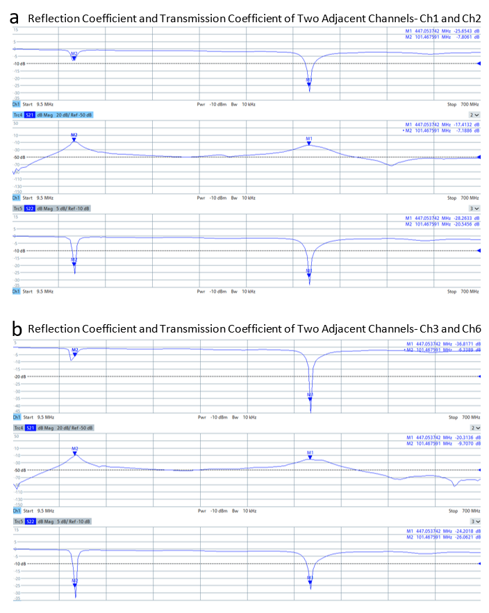
The 2nd mode (i.e. the high frequency mode or high impedance mode) of the 5-cm CTL resonators was tuned to 447 MHz and matched to system 50 Ohms, as shown in Fig 1 (c). Phantom images and B1 maps from the CTL resonator were acquired on the 10.5T whole body MR scanner. The B1 strength per square-root input power is in the range of 2uT (Fig 1(d)). The 5-cm CTL formed 8-channel transceive array placed on a head phantom is shown in Fig 2 (a) and (b). Transmission coefficients of the 8 channels were measured -17 dB or better for Mode 2 (447MHz) and approximately -6~ -10 dB for Mode 1 (103MHz) (Fig 2 (c) and (d)). Plots of transmission coefficients and reflection coefficients of two pairs of adjacent channels, i.e., Channel 1 and Channel 2, and Channel 3 and Channel 6, indicate Mode 2 (high frequency mode) has significantly better decoupling performance than Mode 1 (i.e. low frequency mode), as shown in Fig 3. Figure 4 shows that the active detuning circuit, when active, can generate a very large frequency shift of ~215MHz, indicating the feasibility and efficacy of the proposed detuning circuit. Loaded and unloaded Q-factors of a single 5-cm transceiver CTL resonator measured 29 and 70, respectively. The Q-ratio is 2.4:1. In the receive-only CTL resonator with the detuning circuit, loaded and unloaded Q-factors measured 24 and 72.7, respectively, which yields a Q-ratio of 3.1:1.Conclusions
In this work, we have successfully designed and investigated a flexible patch RF array using the high frequency mode of coaxial transmission line resonators for MR imaging at 10.5T. Sufficient decoupling can be achieved among the small sized 5-cm CTL resonators for 10.5T applications without the use of an extra decoupling network. Additionally, the 447MHz CTL resonator can provide adequate B1 efficiency. Our results also demonstrate that the CTL resonators can be detuned by using the appropriate detuning circuit. Therefore, it is possible to build high-density receive-only arrays using CTL resonators for 10.5T MR imaging with potential practical advantages compared to standard technology.Acknowledgements
This work is supported in part by the NIH under a BRP grant U01 EB023829 and U01 EB025144, BTRC P41 EB027061, P30 NS076408, NIH S10 RR029672, and by State University of New York (SUNY) under SUNY Empire Innovation Professorship Award.References
1. T. Ruytenberg, et al., “Shielded‐coaxial‐cable coils as receiver and transceiver array elements for 7T human MRI”, Magnetic Resonance in Medicine, vol. 83, no. 3, pp. 1135–1146, 2020.
2. L. Nohava, et al., "Flexible Multi-Turn Multi-Gap Coaxial RF Coils: Design Concept and Implementation for Magnetic Resonance Imaging at 3 and 7 Tesla", IEEE Transactions on Medical Imaging, vol. 40, no. 4, pp. 1267-1278, April 2021, doi: 10.1109/TMI.2021.3051390.
3. A. Ozen, et al., “Scalable and Modular 8-Channel Transmit and 8-Channel Flexible Receive Coil Array for 19F-MRI of Myocardial Infarction Studies in Large Animals”, Proc. Intl. Soc. Mag. Reson. Med. 30 (2022), 1570
4. P. Roemer, et al. “The NMR Phased Array”, Magn Reson Med. 16(2):192-225, 1990.
5. S. Gaddipati, et al., “High Impedance Loop coil Design for improved EM Decoupling in Multichannel Coil arrays”, Proc. Intl. Soc. Mag. Reson. Med. 29 (2021), 1394
6. K. Payne, et al., “Hairpin RF resonators for MR imaging transceiver arrays with high inter-channel isolation and B1 efficiency at ultrahigh field 7 T”, Journal of Magnetic Resonance, Vol. 345, 2022, https://doi.org/10.1016/j.jmr.2022.107321
7. T Gao, et al., Development of high impedance microstrip resonators for ultrahigh field MR imaging. Proc. Intl. Soc. Mag. Reson. Med. 30 (2022), 4505
Figures