4591
A Comparison Between Shielded and Unshielded RF Antennas for 7T Body MRI1Center for Magnetic Resonance Research, University of Minnesota, Minneapolis, MN, United States
Synopsis
Keywords: RF Arrays & Systems, High-Field MRI
To more fully realize the benefit of UHF MRI, coil designs must be optimized to for pTx and intrinsic SNR performance. In this abstract we compare 5 RF coil array block systems. The first comparison ran is pTx performance, the second comparison is of intrinsic array SNR, and the third tests robustness to top loading. The shielded and unshielded three-loop dipole elements performed better than the single-loop dipole and the shieled helped with top load insensitivity. From these results we conclude that the three-loop dipole coil blocks have superior performance and that the shield doesn’t hurt performance.Purpose
UHF MRI (>= 7T) has the promise of increased signal to noise and contrast to noise ratios. However, to more fully realize the theoretical SNR and CNR gains, coil arrays must be optimized for parallel transmit (pTx) and intrinsic SNR. In this abstract we compare the pTx and intrinsic SNR performance of five different RF coil block setups. Specifically, we propose the addition of an RF shield that allows for on-board electronics and evaluate the affect this RF shield has on pTx and intrinsic SNR performance.Methods
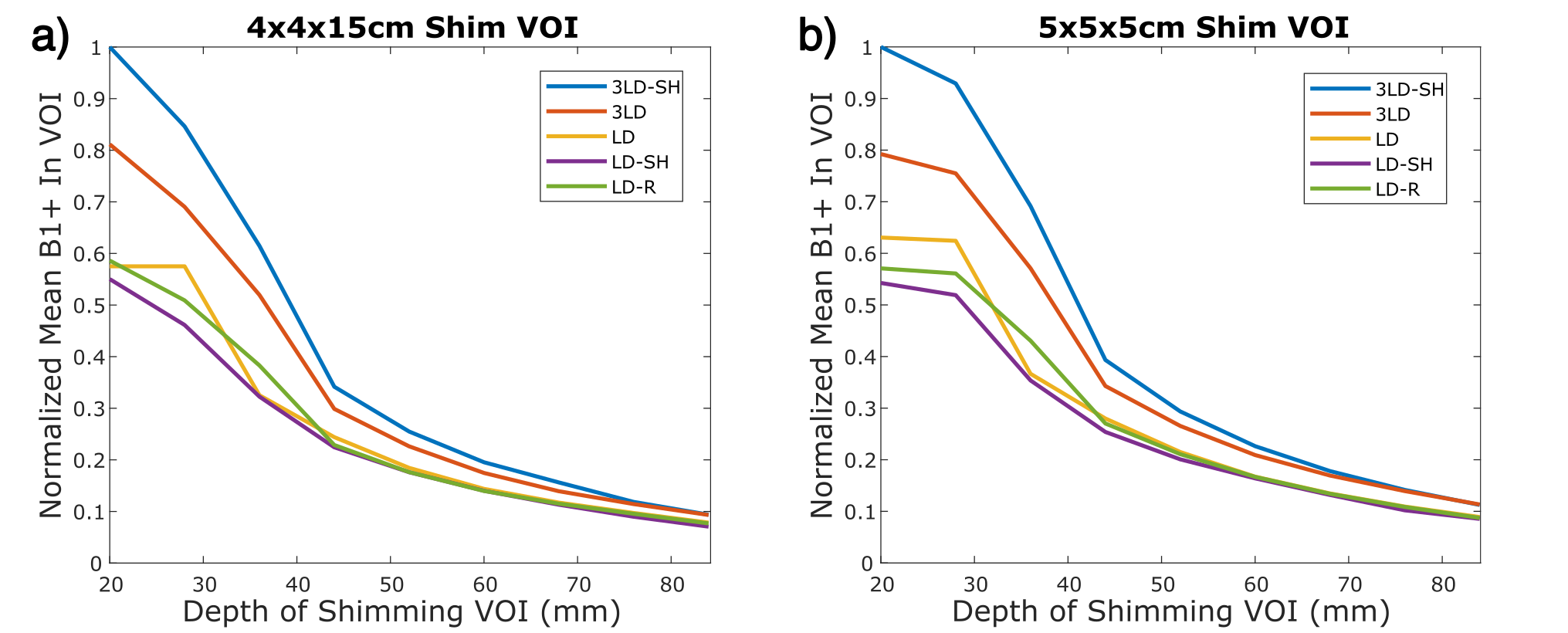
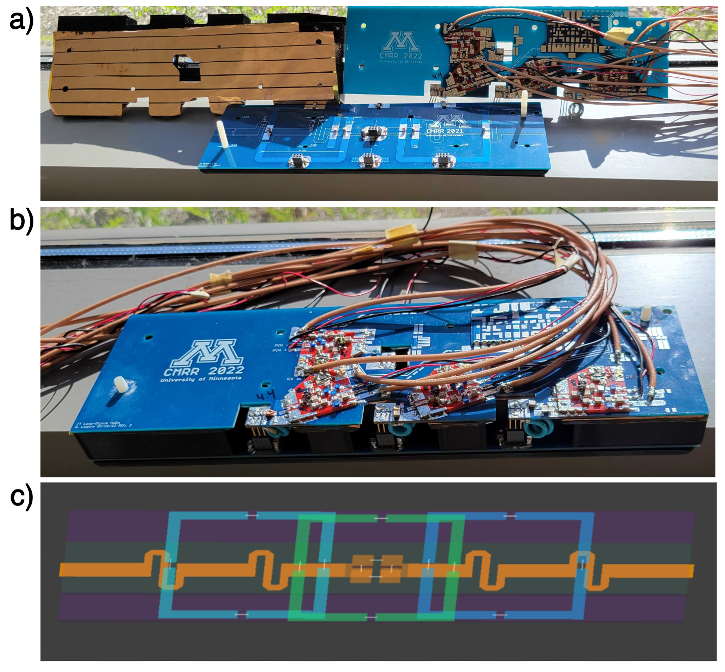
Five different RF coil blocks were constructed and tested in a 7T MRI scanner. These blocks consisted of a single loop-dipole (LD) block, a loop-dipole with an RF shield (LD-SH), a 3loop-dipole (3LD), a 3loop-dipole with an RF shield (3LD-SH), and a LD block from an existing coil array for reference(LD-R)1. The RF shield was constructed from a two-sided flexible PCB with 9µm copper thickness and 25µm substrate thickness. 12mm fingers separated by 1mm slots were etched in the shield to minimize eddy currents2. Since the goal of adding an RF shield is to allow for on-board electronics, a motherboard containing preamplifiers and transmit receive (TR) switches was created and spaced 2cm above the coil elements. For the non-shielded elements, one meter of coaxial cable (K_02252-16, Huber+Suhner) was used to connect the RF antennas to the same motherboard to simulate the existing body coil array setup with off-board electronics.pTx Performance comparison: To compare the pTx performance, a 2D multi-slice B1 relative scan was acquired to obtain relative transmit (B1+) and receive (B1-) profiles3. The channel-wise B1+ maps were normalized to the same input power and used to calculate phase only efficiency shims4 with 5x5x5cm3 and 4x4x15cm3 shimming volumes at different depths. The differences in the RF coil blocks are evaluated based on the mean B1+ at different depths (Figure 1).
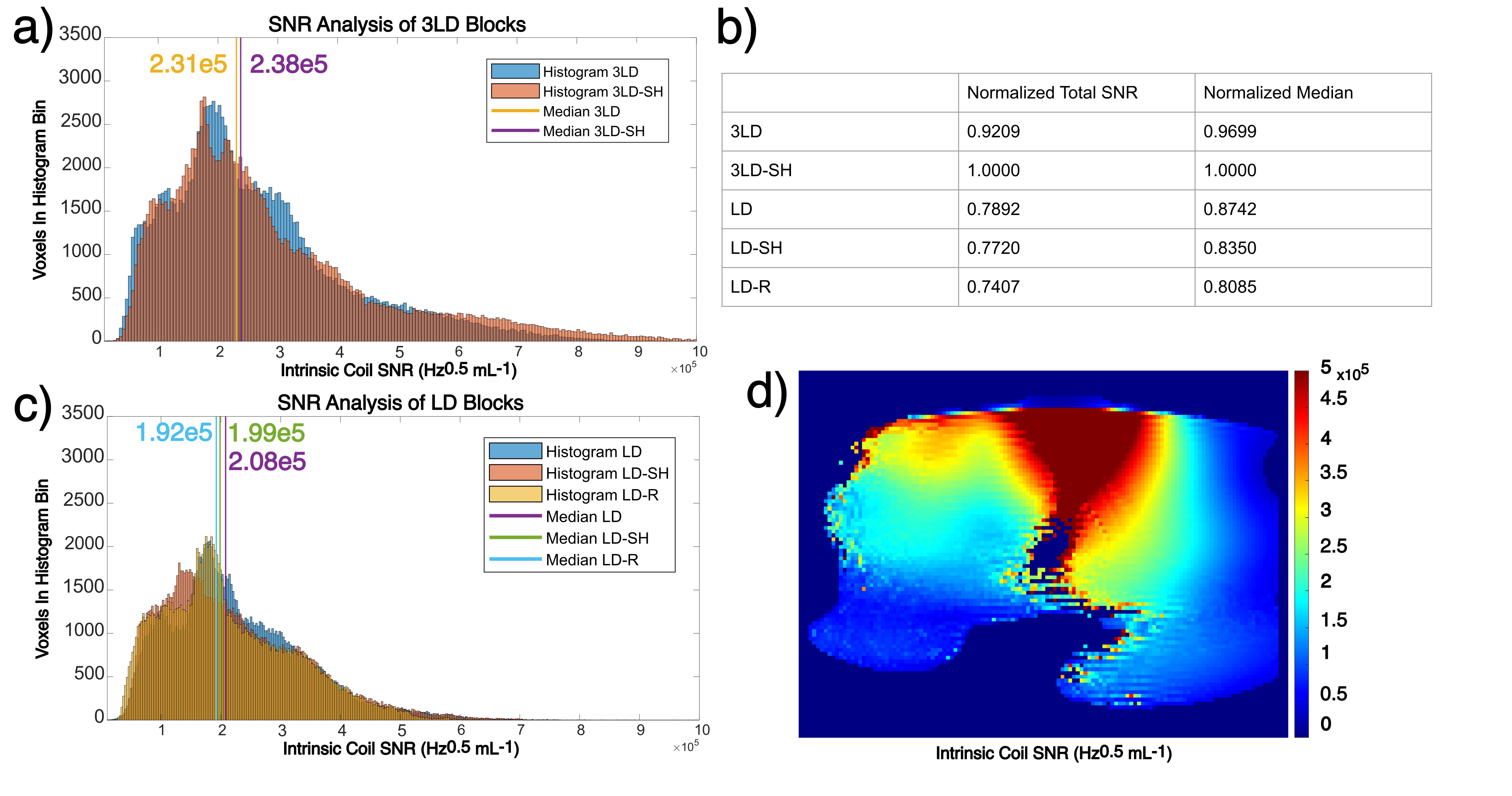
SNR Analysis: One of the theoretical advantages of on-board electronics is the decrease in noise figure (NF) resulting from the elimination of additional cabling between the coil and the preamplifier. The preamplifiers used for this experiment is a SPF5122Z (Qorvo). To measure SNR, an AFI, proton density weighted GRE, and noise scan were collected and used to calculate normalized intrinsic SNR maps for each coil block5. Histograms along with the total SNR and median voxel SNR were then used to compare the RF coil blocks (Figure 2).
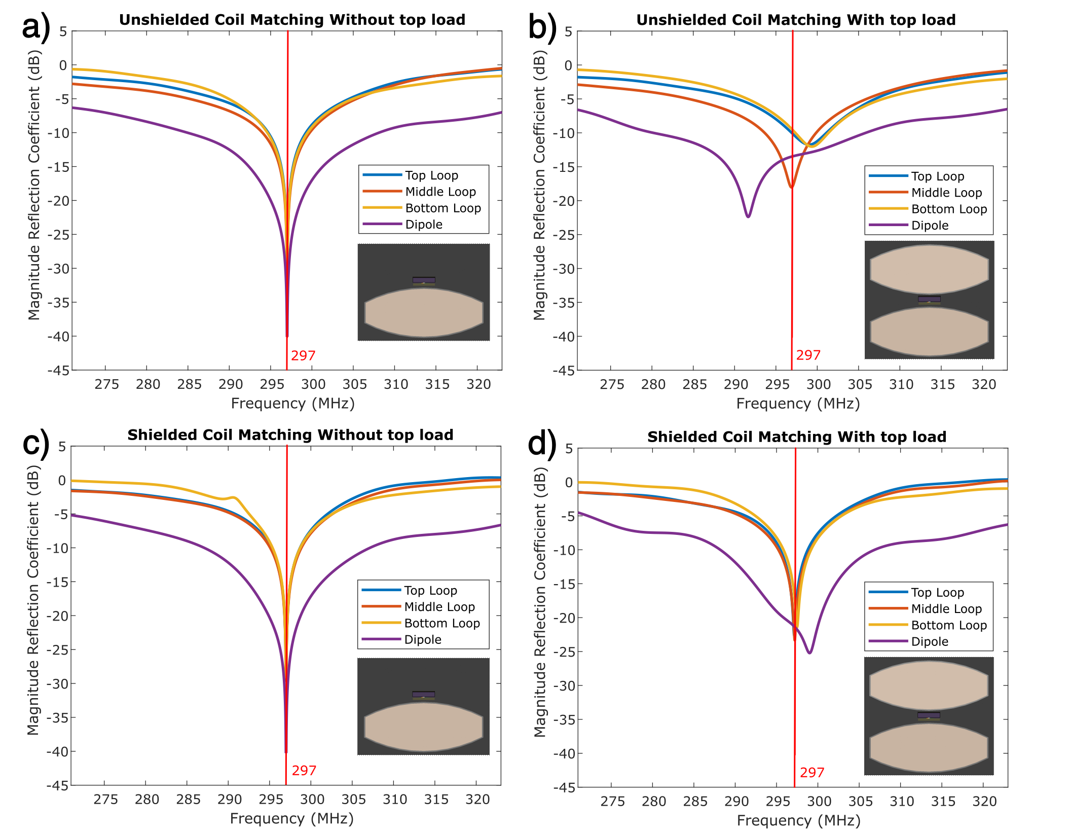
Additional considerations: Along with the SNR and pTx performance of this coil block, another important factor to consider is the robustness to different top loading conditions. To quantitatively test this, the 3LD and the 3LD-SH were simulated on a body phantom, both with and without a top load. The loops and dipole were impedance matched to 50ohms at 297MHz in the simulation without a top load and this matching circuit stayed the same for the top loaded simulation. The reflection coefficient for each coil port was calculated with the results shown in Figure 3.
Results
The proposed 3LD-SH block had better pTx (Figure 1) and SNR (Figure 2) performance than all other blocks tested. Likewise, both 3LD blocks performed better than the single LD blocks in both pTx and SNR. Figure 3 indicates that top loading the 3LD-SH block had less of an affect than top loading the unshielded 3LD block i.e., there was a greater Q broadening and a larger frequency shift on the unshielded block.Discussion
While the 3LD-SH block outperformed the other blocks, the SNR difference between it and the 3LD is only minor. When looking at the normalized median SNR in Figure 2b, there is only a 3% difference between the two. It is feasible that this 3% difference could have resulted from the mask used to filter out low signal regions i.e., the mask artificially favored the 3LD-SH block. A more distinct difference is noted when the 3LD and LD blocks are grouped together. When comparing these two groups, the 3LD blocks perform around 30% better pTx performance and have around 15% higher median SNR. Along with the superior SNR and pTx performance, having a three-LD block design will allow for parallel imaging along the magnet bore direction. Future studies will involve evaluating the SNR and pTx performance of a full 16-transmit 32-recieve 3LD-SH coil array.Conclusion
The pTx performance and intrinsic SNR was compared across 5 unique RF coil blocks. The motherboard that housed the pre-amplifiers and TR switches stayed the same for each of these blocks to eliminate active electronic variability and the effect of adding an RF shield was tested. Our results show that both three-LD blocks outperform the single-LD blocks in both pTx efficiency and SNR, and that the addition of an RF shield doesn’t degrade coil performance.Acknowledgements
Funding was provided by NIH P41 EB027061 and NIH R01 EB029985.References
1. Ertürk, A., Raaijmakers, A., Adriany, G., Uğurbil, K., & Metzger, G. A 16-channel combined loop-dipole transceiver array for 7 Tesla body MRI. Magn Reson Med, 2016; 77(2):884-894.
2. Lechner-Greite, S., Hehn, N., Werner, B., et al. Minimizing eddy currents induced in the ground plane of a large phased-array ultrasound applicator for echo-planar imaging-based MR thermometry. J. Ther. Ultrasound, 2016; 4(1):1-14
3. Brunner, D., Pruessmann, K., SVD Analysis of Array Transmission and Reception and its Use for Bootstrapping Calibration. Magn Reson Med, 2016; 76(6):1730-1740.
4. Metzger, G., Snyder, C., Akgun, C., Vaughan, T., Uğurbil, K., and Van de Moortele P.F. Local B1+ shimming for prostate imaging with transceiver arrays at 7T based on subject-dependent transmit phase measurements. Magn Reson Med, 2008: 59(2):396-409.
5. Van de Moortele, P. F., Akgun, C., Adriany, G., Moeller, S., Ritter, J., Collins, C. M., ... & Uğurbil, K. (2005). B1 destructive interferences and spatial phase patterns at 7 T with a head transceiver array coil. Magn Reson Med, 54(6), 1503-1518.
Figures