4589
16-Channel 11.7T Transmit Array with Integrated Field Probes
Son Chu1, Vincent Gras2, Nicolas Boulant2, and Shajan Gunamony1
1University of Glasgow, Glasgow, United Kingdom, 2University of Paris-Saclay, CEA, CNRS, BAOBAB, NeuroSpin, Gif sur Yvette, France
1University of Glasgow, Glasgow, United Kingdom, 2University of Paris-Saclay, CEA, CNRS, BAOBAB, NeuroSpin, Gif sur Yvette, France
Synopsis
Keywords: RF Arrays & Systems, RF Arrays & Systems
Transmit arrays are essential to mitigate B1+ inhomogeneity at extremely high static magnetic field strengths. In addition, the transmit elements must be arranged in multiple rows to achieve whole-brain coverage at 11.7T. Furthermore, concurrent field monitoring probes offer the possibility to improve MR image quality by correcting subject-specific k-space trajectories and monitoring real-time dynamic field fluctuations. The placement of these probes must be carefully controlled to achieve proper probe conditioning as well as to preserve the RF performance of the transmit array. This work presents the numerical simulation and optimization of a 16-channel-transmit array with integrated field probes.Introduction
A workflow combining 3D electromagnetic (EM) and RF pulse design (RFPD) simulations to achieve efficient excitation within SAR constraints for transmit array designs at 11.7T was developed1. The proof-of-concept study included an 8-channel-transceiver array with a folded-end RF shield to minimise radiation loss1. We have extended this approach to the development of a 16-channel-dual-row-transmit array, which achieves whole-brain coverage at 11.7T. To increase the signal-to-noise ratio (SNR), it will be combined with a 32-channel-receive array. Additionally, concurrently monitoring dynamic field fluctuations during MR image acquisition at 7T and beyond can improve image quality and reduce artifacts2. However, optimal placement of field probes is essential to achieve probe conditioning and minimal interaction with the transmit array.This work presents the optimization of a 16-channel-dual-row-transmit array using the workflow above. Then,16-field probes are integrated into the numerical model of the optimal transmit array. The probe positions were controlled to preserve the array's transmit performance.
Methods
A 16-channel-transmit array (array-δ) was developed using the optimisation process presented earlier1. To achieve whole-brain coverage, a dual-row configuration consisting of two rows of eight rectangular loops covering 180mm in the z-direction was selected. EM simulations were conducted in CST Studio Suite 2021 (Dassault Systems, France)3 to optimise the transmit performance while the optimum configuration for mitigation of RF field inhomogeneity was chosen by RFPD simulations4.The numerical model included the transmit array, coil housing, scanner bore, discrete component losses, and cable losses up to the coil plug. The array elements were arranged on a fiberglass tube (εr=5.5, tanδ=0.04, inner diameter 285mm, wall thickness 2.5mm), and the lower row elements were rotated by 22.5° (Fig. 1a). The coil was loaded with Duke body model (virtual family, 2mm resolution) truncated below the level of shoulders. Each array element consisted of 11-fixed capacitors and one variable capacitor The capacitors were connected by 2mm diameter wires. Adjacent elements were decoupled using geometric overlap and the diagonal elements were decoupled using transformer decoupling5.
To reduce radiation loss at 11.7T, a folded-end shield1 was designed and optimised in conjunction with the array. Previously, we found improvement in transmit performance by increasing the shield diameter1, but this would offset the coil from the iso-centre. Therefore, in addition to 400mm (δ1) and 450mm (δ2) shield diameter, an asymmetric shield with a flat base (δ3) was also investigated because the coil sits lower on the patient table while the sides can be extended up to 450mm in diameter (Fig. 1b). The shield length was varied from 260mm to 300mm in 10mm increments.
Fig. 1c shows the CAD model for the full apparatus consisting of the transmit array with a receive array and optimal probes’ positions. The field monitoring probes were placed in pockets created on the enclosure of the receive array. Since the probes are shielded, they were modelled as solid copper structures in CST. However, their coaxial cables were not included. Positions for the probes were determined iteratively using a MATLAB programme (Skope MRT AG, Switzerland) and CST to achieve optimum probe conditioning and to minimise their influence on transmit efficiency.
Results and Discussion
Simulated results in Fig. 2 show that the array with an asymmetric shield (δ3) electromagnetically performs equally as array δ2, which has 450mm shield diameter. The asymmetric shield was chosen for further optimisation due to its lower height. Remarkably, this configuration also exhibits smaller NRMSEs of the kT-points for all three different pulses (Fig. 2c). Similar to the previous study1, we found no direct relationship between the shield length and radiated power. Among the arrays under investigation, δ3(280) was preferred because it provided the least radiation loss, a compact design, and a more homogeneous B1+ field (Fig. 2d and 2f). Fig. 3 presents the simulated S-parameters of δ3(280) loaded with the Duke model. At 499.415MHz, the average couplings between the adjacent, next-neighbouring, and diagonal elements are lower than -15dB with a maximum coupling of about -12dB. The reflection coefficients were better than -40 dB with no resonant peak splitting.Using the software for probe conditioning, the following results were observed: for a FOV of 20cm at the coil’s iso-centre, the simulated mean field noise was comparable to the probe phase noise with a maximum value of fewer than three times the probe phase noise within 50kHz bandwidth.
Fig. 4 compares the CP mode B1+ maps for δ3 (280) in three different cases: (i) without the probes, (ii) with the probes but without retuning, and (iii) with the probes and retuning. These results demonstrate that the transmit performance can potentially be preserved by the appropriate selection of the positions of the probes regardless of channel retuning. The routing of probes’ feeding cables as well as the placement of traps on the cables will be determined empirically.
Conclusion
We have presented simulation results of a 16-channel-dual-row-transmit array with commercial field probes for B0-field monitoring for MRI at 11.7T. The array is currently under construction and will be combined with a 32-channel-receive array to increase SNR. Combining EM and RFPD simulations is a rigorous numerical method for coil design at 11.7T. Also, placing the probes in optimal locations can prevent RF interactions and hence, preserve the transmit efficiency.Acknowledgements
This project has received funding from the European Union’s Horizon 2020 research and innovation programme under grant agreement No. 885876 (AROMA). The authors acknowledge great customer support and useful discussions with Simon Gross and David Brunner from Skope MRT AG.References
- Chu S. et al. Design and Optimization of Transmit Arrays for MRI at 11.7T. Joint Annual Meeting ISMRM-ESMRMB and ISMRT, London, United Kingdom, 2022.
- Barmet, C., Zanche, N.D. and Pruessmann, K.P. Spatiotemporal magnetic field monitoring for MR. Magn. Reson. Med. 2008, 60(1), 187-197.
- Hoffmann, J. et al. Numerical and experimental evaluation of RF shimming in the human brain at 9.4 T using a dual-row transmit array. Magn Reason. Mater. Phys. Biol. Med. 2014, 27(5), 373-386.
- Hoyos-Idrobo, A. et al. On variant strategies to solve the magnitude least squares optimization problem in parallel transmission pulse design and under strict SAR and power constraints. IEEE Trans. Med. Imaging. 2013, 33(3), 739-748.
- Shajan, G. et al. A 16-channel dual-row transmit array in combination with a 31-element receive array for human brain imaging at 9.4 T. Magn. Reson. Med. 2014, 71(2), 870-879.
Figures
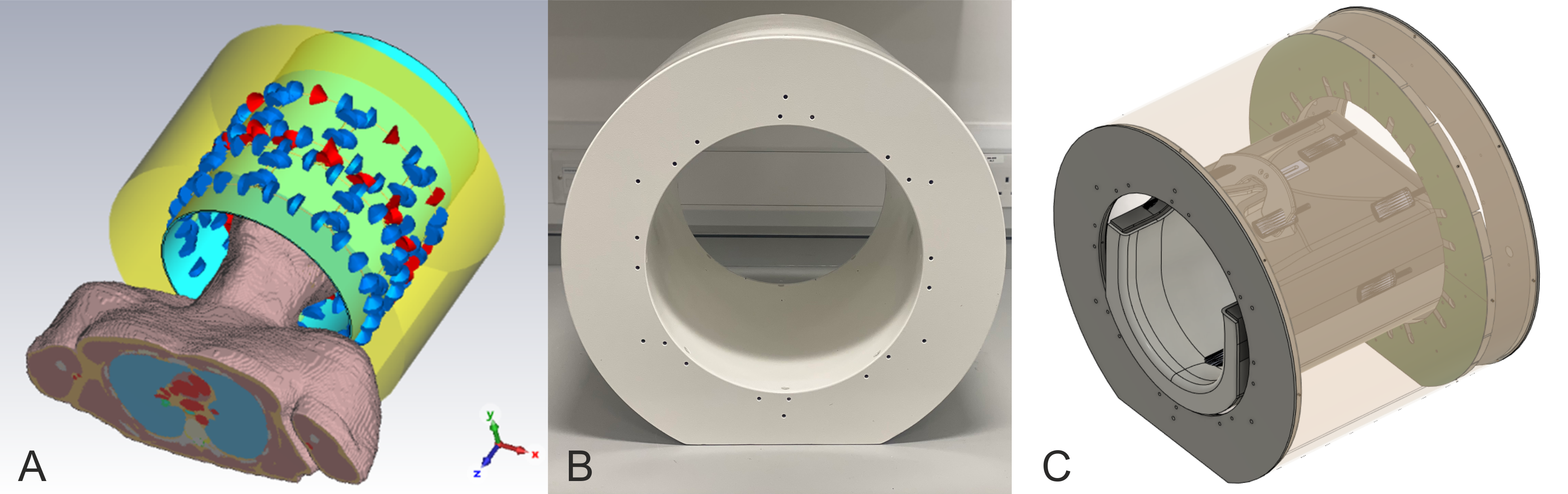
(a) Numerical model of the transmit array loaded with the
Duke body model. The lumped elements (capacitors, blue), and the simulation ports
(red) are shown. (b) Photograph of the asymmetric folded-end shield. (c) CAD
model of the 16-channel-transmit/32-channel-receive array with 16 clip-on field
probes.
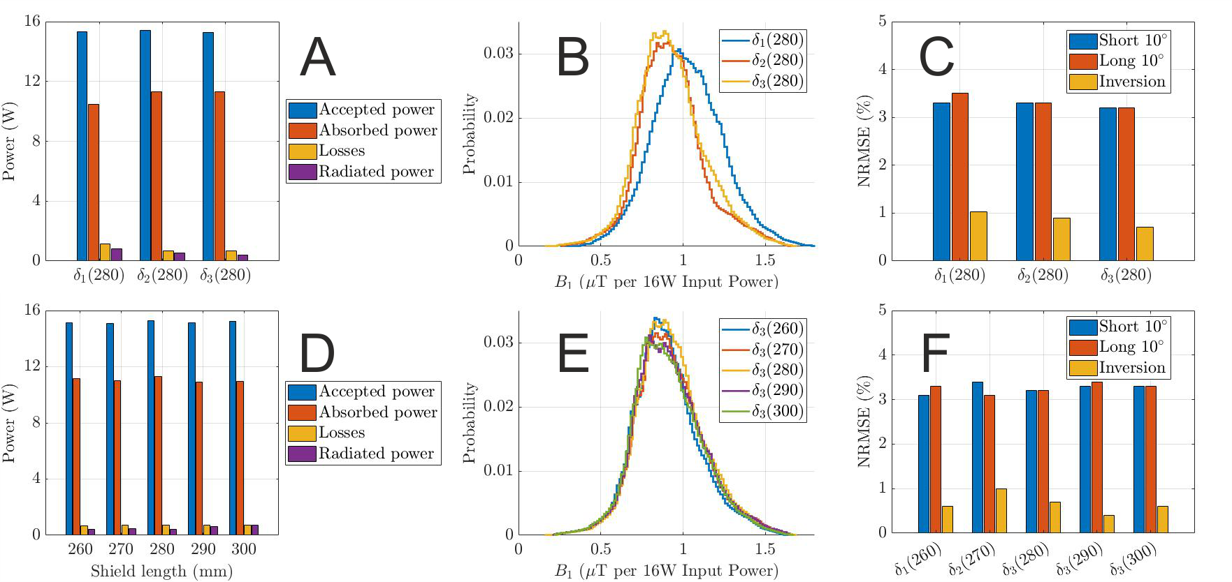
Power budget (a, d) and histogram (b, e) of the magnitude of the B1+ fields for 16W input power (CP mode) in the brain tissues for δ1, δ2, and δ3 designs with the same shield length of 280mm, and δ3 designs with five different shield lengths, respectively. The coefficients of variation are δ1(280)=25%, δ2(280)=23.3%, δ3(260)=25.8%, δ3(270)=26.3%, δ3(280)=25.2%, δ3 (290)=26%, and δ3(300)=25.4%. (c, f) NRMSEs in percent for three different RF pulse design simulations: short duration 10°, long duration 10°, and inversion pulses.
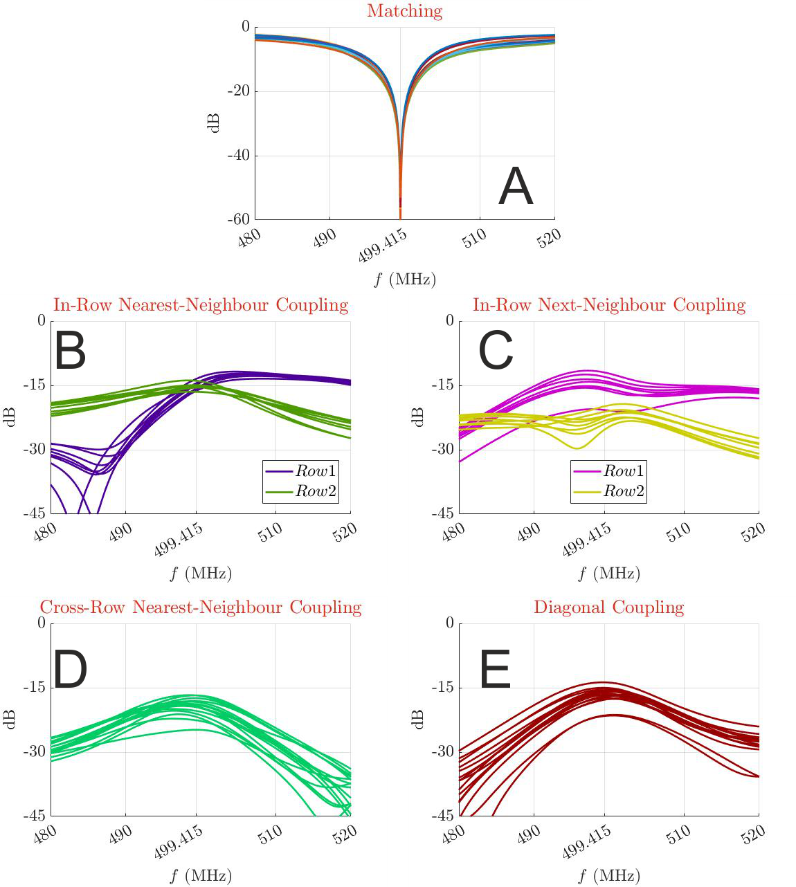
Reflection (a) of the optimum array δ3(280). On average, the transmission coefficients are as follows: nearest-neighbour couplings (b) -15.0dB for row 1 and -15.4dB for row 2; next-neighbour couplings(c) -15.2dB for row 1 and -22.5dB for row 2; cross-row coupling (d) -19.6dB; and diagonal coupling (e) -17.0dB. No coupling is greater than -12dB.
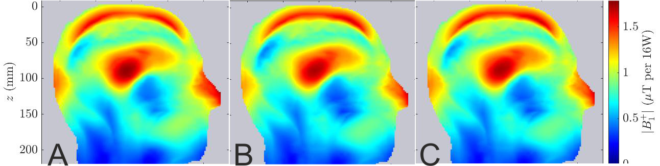
Sagittal slice of B1+ field maps for 16W input power (CP mode) in the DUKE virtual family model for three different cases: (a) without field probes, (b) with field probes but non-retuning, and (c) with field probes and retuning. The peak B1+ values in the middle of the brain for these three cases are 1.76μT, 1.71μT, and 1.73μT, respectively.
DOI: https://doi.org/10.58530/2023/4589