4586
Compact 7T: Progress in Construction and Assembly of a Low-Cryogen, High-Performance, Head-only High-Field MRI System
Thomas Foo1, Mark Vermilyea1, Gene Conte1, Chris Van Epps1, Justin Ricci1, Minfeng Xu1, Anbo Wu1, Shike Huang1, Seung-Kyun Lee1, Wolfgang Stautner1, Bai Ye1, Doug Kelley2, John Huston III3, Matt A Bernstein3, Yunhong Shu3, Christopher Hess4, and Duan Xu4
1GE Research, Niskayuna, NY, United States, 2GE Healthcare, Waukesh, WI, United States, 3Mayo Clinic, Rochester, MN, United States, 4University of California-San Francisco, San Francisco, CA, United States
1GE Research, Niskayuna, NY, United States, 2GE Healthcare, Waukesh, WI, United States, 3Mayo Clinic, Rochester, MN, United States, 4University of California-San Francisco, San Francisco, CA, United States
Synopsis
Keywords: High-Field MRI, Magnets (B0), Cryogenics; Low-Cryogen; Compact
Steps in the construction of an 8 metric ton, 7.0 T MRI scanner for imaging the brain are described. The system nearing completion uses only 12 liters of liquid helium and has outside dimensions comparable to a clinical whole-body 3.0 T scanner, with a similar footprint. As such, the new Compact 7.0 T system fits into any whole-body 3.0 T room, simplifying installation. The system is in the final stages of assembly.Introduction
High-field MRI systems have been pursued primarily to increase the image signal-to-noise ratio (SNR) for high-resolution brain imaging, increased susceptibility contrast, and greater separation of important brain metabolites for MR spectroscopy (MRS). However, whole-body 7.0 T MRI scanners are large and heavy (between 20-40 tonnes), have large footprints (5 Gauss footprint of 116-160 m2, and require extensive magnetic shielding (80-120 tonnes). These factors increase scanner costs and installation costs, because additional space and floor reinforcement are required. Additionally, conventional 7.0T human magnets require several thousand liters of liquid helium during installation and operation, presenting a substantial expense and a logistical challenge. Our 7.0 T magnet design, completed in 2021 [1], is a brain imaging system (that is also capable of scanning extremities) and has the weight and footprint of a clinical whole-body 3.0 T MRI scanner, without the need for additional magnetic shielding. As such, it can easily replace any whole-body 3.0 T MRI system, providing new capabilities to utilize high-field 7.0 T MRI for clinical brain imaging and neuroscience research. We note that this system design will accommodate knee exams, as brain and knee exams are currently the mainstay of whole-body, clinical 7T MR. We describe recent progress on the construction and assembly of the low-cryogen Compact 7T (C7T) MRI scanner as we approach ramping the magnet to field and generating the first images.Theory and Design
The magnet specification [1] calls for a B0-field homogeneity of <1.0 ppm over a 26-cm field-of-view. To achieve this target field homogeneity, C7T incorporates a superconducting shim assembly that has 6 axial and 12 transverse shim sets, which also reduces the amount of passive shim material required. As with the Compact 3T system [2], the passive shim system utilizes 48 trays arranged azimuthally and running the length of the magnet, providing the fine adjustment of the magnet field homogeneity.The magnet coils (6 main coils and 2 bucking coils) were mounted inside of aluminum support cylinders. As an initial test, the assembly was operated at 0.05 A current to generate an 8 Gauss field to assess the quality of the “wake-up” field at room temperature (i.e., ``warm mapping’’) and to verify that the superconducting shim assembly has sufficient capability to achieve the target field homogeneity with an acceptable mass of passive shim material. Magnet coil leads, superconducting shim coil leads, the closed-loop sealed helium system, and temperature sensors were then assembled onto the main support structure to complete the ``insert’’. The next steps will be enclosing the assembly in a thermal shield and vacuum vessel, creating the vacuum, cooling the coils/assembly to 4K.
The final assembly has 12 liters of liquid helium at 4K. This follows simulations to estimate heat load from magnet-gradient interactions, and the capacity/pressure targets of the helium tanks. With an assumed 1.5 W static heat load, the three cold-heads/cryocoolers (Sumitomo RDE-412, with each providing 1.5 W at 3.4 K) will provide sufficient capacity to cool the cryogenics to ~3.5K.
Results
Figure 1 shows the superconducting shim coil capability for the different magnetic field spherical harmonic components and room temperature, low-field measurements (``warm mapping’’). The results show that the majority of the field harmonics are within the capability of the superconducting shim coils, except for the (2,-1 : ZX) harmonic (Table 1). We also noted that the (4,0 : Z4) harmonic was quite close to the limit of the shim coils. The ``warm mapping’’ data indicated that apart from these two specific harmonic terms, there residual field inhomogeneity can be corrected by the passive, room temperature shims without the need to add additional ``cold iron’’ to the magnet assembly. As such, we expect <2000 shim pieces (~1.2 kg of iron) will be required for the system passive shims to achieve the target <1.0 ppm field homogeneity.Figures 2-4 show the magnet cold mass in different stages of assembly. On completion of the cold mass assembly, the thermal shield with multi-layer insulation will be assembled prior to welding the entire magnet assembly in a vacuum vessel. The C7T has the same electronics as a whole-body 7.0T system (GE SIGNA 7.0 T) with a 900 A/2150 V gradient driver. As such, the head-only gradient coil produces 140 mT/m at 820 T/m/s, providing EPI echo spacing of <450 μs for 1.5-mm isotropic scans.
Conclusion
Steady progress has been made with the C7T with a ramp-to-field and first images expected in May-2023. Superconducting shim coils and passive shims are expected to bring the B0 homogeneity to the target <1 ppm level without requiring excessive room-temperature passive shims. The final assembly is expected to reach stable cryogenic operation with ~12 liters of liquid helium, based on estimated heat load from magnet-gradient interactions, and the capacity/pressure targets of the helium tanks.Acknowledgements
This project was funded by NIH U01EB027696.References
1. Foo TKF, Vermilyea ME, Xu M, et al. Proc. of the ISMRM 2021; 29: 561.
2. Foo TKF, Laskaris E, Vermilyea M, et al. Magn Reson Med 2018; 80: 2232–2245.
Figures
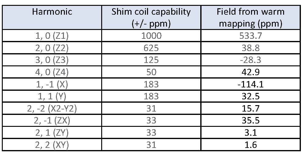
Figure 1: Magnetic field harmonics on a 26-cm diameter spherical volume (DSV) showing the capability of the superconducting shim coils, the prediction from ``warm mapping’’.
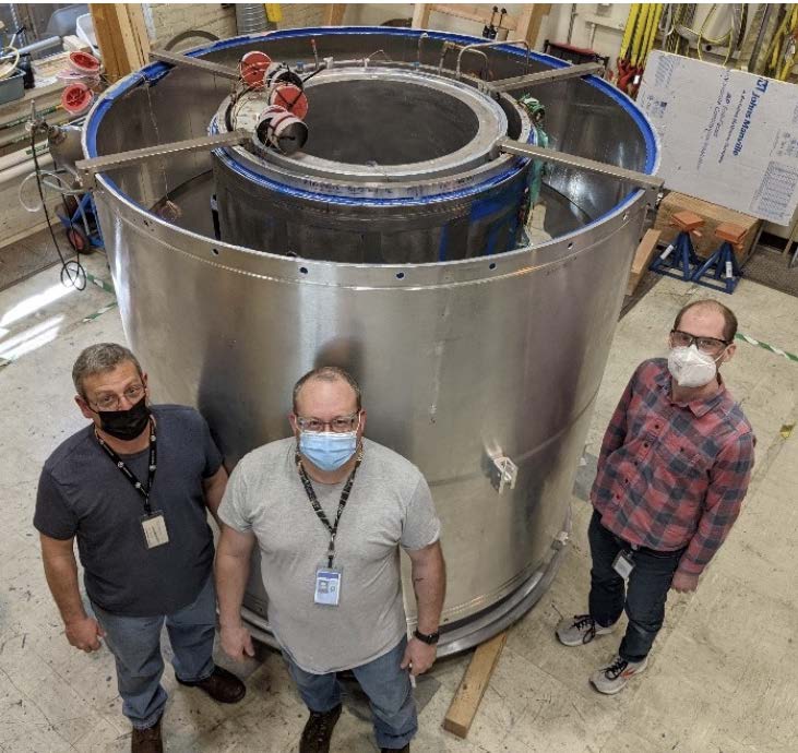
Figure 2: Assembly of the main magnet coils (inner cylinder), shim coils (intermediate cylinder), and the large bucking coils (outer cylinder). The overall size of C7T is better appreciated in this view.
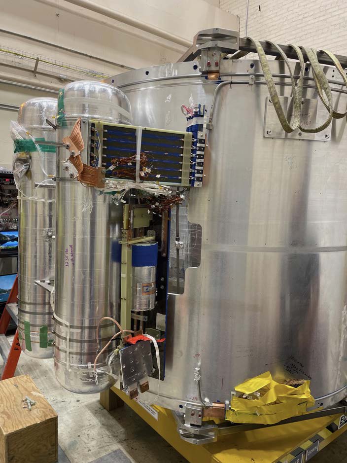
Figure 3: Mounting of the helium tanks to the outer coil support structure. The rectangular superconducting shim lead panel is also shown.
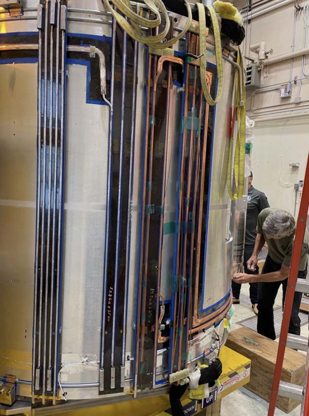
Figure 4: Obverse view of the C7T magnet in final stages of assembly showing the routing of the magnet coil leads.
DOI: https://doi.org/10.58530/2023/4586