4584
Denoising Effect of Double-Loop Spiral Coil with ultra-High Dielectric Constant Materials for MRI Applications1Center for NMR Research, Departments of Neurosurgery and Radiology, College of Medicine, Pennsylvania State University, Hershey, PA, United States, 2Engineering Science and Mechanics, Pennsylvania State University, state college, PA, United States, 3Center for Magnetic Resonance Research, Department of Radiology, University of Minnesota, Minneapolis, MN, United States
Synopsis
Keywords: Non-Array RF Coils, Antennas & Waveguides, High-Field MRI, High dielectric material
We investigated the denoising effect of employing double-loop spiral coil (DLSC) versus the conventional single loop surface coil in the presence of ultrahigh dielectric constant materials (uHDCM). The DLSC confines the conservative E-field distribution between the loops which as a result reduces the E-field in the sample, therefore reduces the noise level. Reduction of conservative E-Field makes the non-conservative E-field more dominant in the sample, which synergistically with the noise reduction allows increasing transmit efficiency and receive sensitivity for MRI application.Introduction:
A large denoising effect with the ultrahigh dielectric constant materials (uHDCM) and a conventional single-loop surface coil was demonstrated for 23Na imaging at 10.5T and 17O imaging at 7T magnets [1]. It was shown previously that B1 field can be enhanced several folds in the sample by induced strong displacement current in uHDCM next to the sample [2, 3]. The displacement current in uHDCM is produced by non-conservative E field induced by the coil. The E field by the RF coil in the sample consists of both conservative and non-conservative components, both of which produce losses and generate noises in a conductive sample [4]. This decomposition of the E-field is shown in Eq. 1,$$E={\overrightarrow{-\triangledown\phi}}-jω\overrightarrow{A}$$ (1)
Where φ is the electric scalar potential, A is the vector potential, and ω is the angular frequency.
It was shown in [1] that employing uHDCM increase the induced displacement current and therefore enhance the B1 field, also reduces the conservative field and decreases the MR imaging noise. For further reduction of conservative E-field, in this work we propose using dual loop spiral surface coil and therefore achieving more enhancement of of RF magnetic transmission field (B1+) efficiency and reception field (B1-, Rx-sensitivity).
Methods:
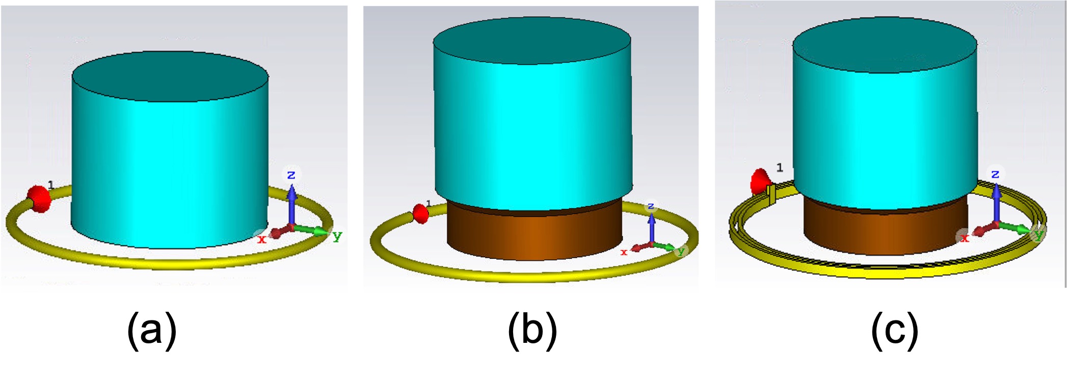
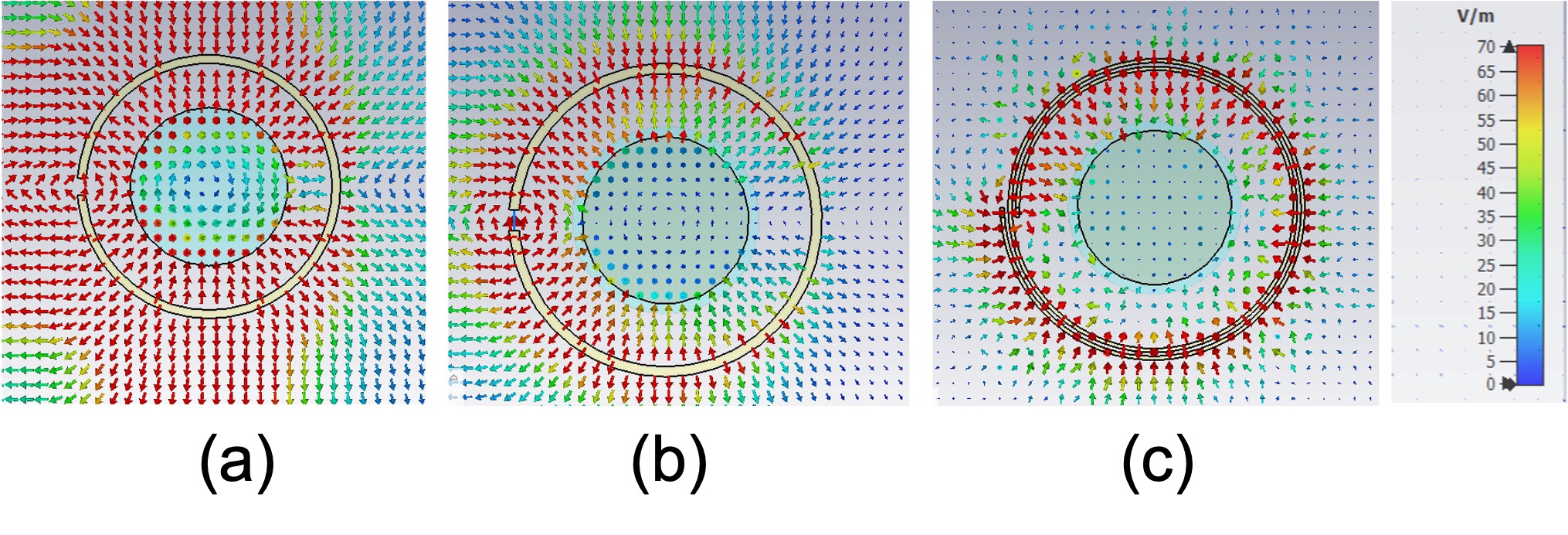
Simulation setup: We performed the numerical calculation of Maxwell equations by using CST Microwave Studio as a full-wave simulation software. The setup (Fig. 1) includes a 15 cm diameter coil of a copper wire, a cylindrical uHDCM disk, and a cylindrical water phantom placed on top of the uHDCM disk. The thickness and diameter of the uHDCM disk is chosen as 2.1 cm and 8 cm, respectively. The electrical properties of the water phantom with the diameter of 9 cm and height of 11 cm, is chosen εr=80 and σ=1.5 S/m. The one loop coil and DLSC radii are chosen 7.5cm and, matched to 50 Ohm and tuned at 63MHz (close to 17O Larmor frequency at 10.5T). To perform our investigation, we studied the field at employing uHDCM with εr = 6000, and then compared the value of normal electric field at the phantom and the Rx-sensitivity of the coil for three cases of investigation.Electric field map has been extracted in vector form at axial cross-section and compared for 1) Single loop coil with phantom in the center and in the absence of the uHDCM disk (Baseline), 2) single loop coil, and 3) DLSC with phantom in the center on top of the uHDCM disk.
Rx Sensitivity gain and Noise Level (NL) reduction: The Rx-sensitivity is calculated by dividing the B1- over the square root of the dissipated power within the phantom at 63MHz. The normalized noise level (NNL) can be calculated using Eq. 2,
$$ NNL=\sqrt{\frac{\int_{a}^{b} \sigma(E^{2})}{avg((B_1^+)^{2})}}$$ (2)
The integration is performed in the whole volume of the phantom. Based on (Eq. 2), by the reduction of E-field in the phantom, the NNL value received at the loop will reduce and therefore the Rx sensitivity increases.
Results and Discussion:
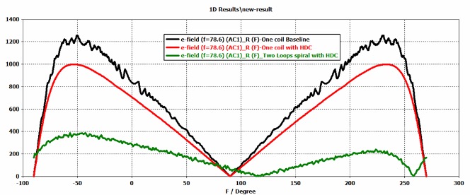
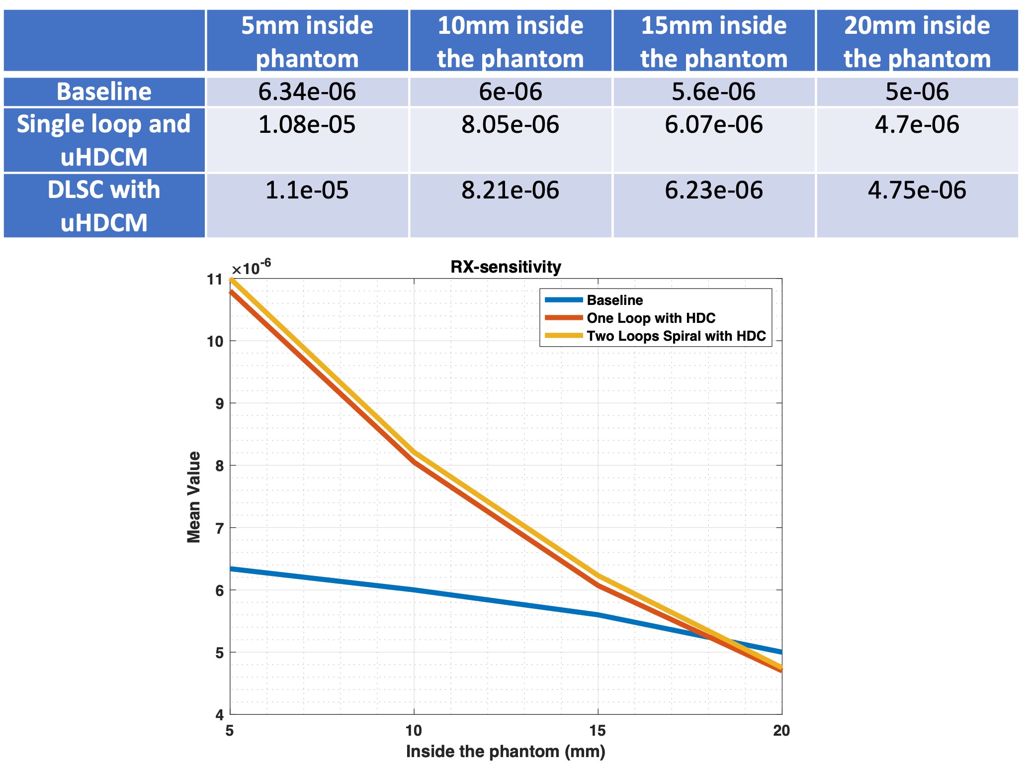
As shown in Fig. 2a, the E-field in the sample region for the baseline consists of a set of parallel lines indicating a conservative field. In the presence of the phantom the E-field vectors in the phantom follow circular lines, indicating the field is dominantly non-conservative inside the phantom, while outside the phantom, the E-field is dominantly conservative. The conservative E-field is produced by the surface charges of the coil and those of the phantom with opposite charges. The E-field intensity is also decreased within the phantom. However in the presence of uHDCM (Fig. 2b-c), we observed that the conservative E-field at the boundary of the phantom is reduced compared to Fig. 2a. The line plot in Fig. 3 quantitatively reveals this reduction of conservative field. We found the least E-field at employing DLSC, which leads to a significant reduction of the noise level. Table 1 and Figure 4 show the Rx-sensitivity for all three cases in small planes parallel to the coil position inside the phantom. The Rx-sensitivity is enhanced by using the uHDCM disk and double-loops spiral coil in from the surface to 15 mm depth inside the phantom. Our future investigation would be the array of new design coil to further enhance sensitivity for the whole phantom volume.Conclusion:
With computer modeling under an identical setup, we demonstrated that although the uHDCM reduces the conservative E-field and noise level, employing the DLSC can be useful to achieve even more reduction of conservative E-field and therefore enhance the B1+ efficiency in the phantom and Rx sensitivity at the coil loop. This property leads to a prominent de-noising effect and can immediately benefit the many MRI applications.Acknowledgements
This work is partly supported by NIH grants of R01 CA240953 and U01 EB026978.References
[1] W. Chen et al., "Tunable Ultrahigh Dielectric Constant (tuHDC) Ceramic Technique to Largely Improve RF Coil Efficiency and MR Imaging Performance," in IEEE Transactions on Medical Imaging, vol. 39, no. 10, pp. 3187-3197, Oct. 2020.
[2]Yang, Q.X., Rupprecht, S., Luo, W., Sica, C., Herse, Z., Wang, J., Cao, Z., Vesek, J., Lanagan, M.T., Carluccio, G., Ryu, Y.-C. and Collins, C.M. (2013), Radiofrequency field enhancement with high dielectric constant (HDC) pads in a receive array coil at 3.0T. J. Magn. Reson. Imaging., 38: 435-440. https://doi.org/10.1002/jmri.23988
[3] Rupprecht, S., et al., Magnetic Resonance in Medicine, 2017. 79(5).[4] Roemer, P. B., Edelstein, W. A., Hayes, C. E., Souza, S. P. and Mueller, O. M., The NMR phased array. Magnetic Resonance in Medicine, 1990.
Figures