4583
Simulation and Comparison of Transmit Elements for 7T Head-Imaging with a Large Diameter Transmit Coil1Siemens Healthineers GmbH, Magdeburg, Germany, 2Otto-von-Guericke University, Magdeburg, Germany, 3Research Campus STIMULATE, Magdeburg, Germany, 4Deutsches Krebsforschungszentrum Heidelberg, Heidelberg, Germany, 5Physikalisch-Technische Bundesanstalt (PTB), Berlin, Germany
Synopsis
Keywords: Non-Array RF Coils, Antennas & Waveguides, Non-Array RF Coils, Antennas & Waveguides
12 transmission coil designs for 7T head imaging are compared using EM simulations for a large diameter transmit coil. The highest power and SAR efficiency are achieved by loop coils, a passively-fed dipole shows the highest intrinsic decoupling and an IMARS the lowest load dependence. The results provide insight to each element's performance. To make a final decision on a coil element, the array performance must also be evaluated in the futur, as this may differ from the performance of the single element performance. Thus, the decision on a particular transmit element depends on the coil's application and configuration.Introduction
Many different transmit element designs for 7T head imaging were introduced and even more have been proposed for body imaging1-12. Most of these designs target specific applications and are placed close to the subject to ensure high transmit efficiency. This proximity, however, can cause claustrophobia6. Additionally, they provide limited space for further devices such as external stimulation or physiologic monitoring, which are frequently used in neuroimaging13,14. Hence, a transmit coil with a larger distance between patient and coil would benefit patient comfort and access. This contribution compares different transmit element designs for 7T head imaging using EM simulations for a large diameter parallel transmit coil.Material and Methods
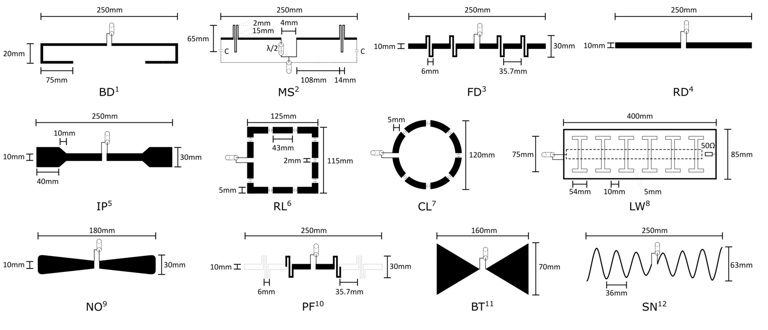
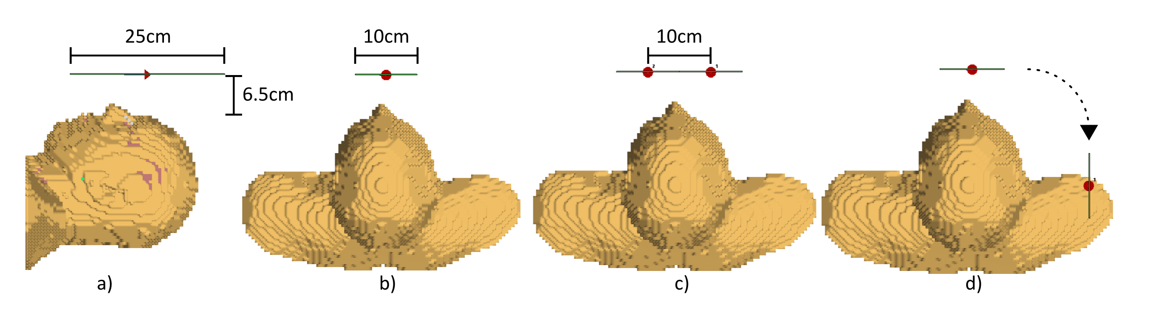
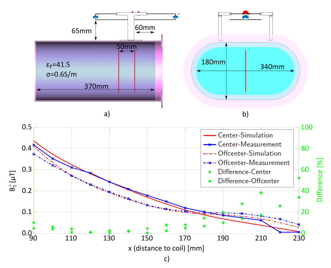
For this study, 12 antenna designs1-12 were evaluated. Figure 1 shows the designs and their dimensions. The simulations were performed in CST Microwave Studio 2022 at 297.2MHz. The antennas were loaded with the head of the body model Hugo, which is placed as depicted in figure 2a-b. All antennas are adjusted to |S11|=-50dB input reflection. The power efficiency ($$$|\text B _1^+|/\sqrt {\text P}$$$) normalized to 1W of input power and SAR efficiency ($$$|\text B _1^+|/\sqrt {\text pSAR}$$$) as well as the intrinsic coupling and the load dependence were evaluated in simulation. The peak power and SAR efficiency were evaluated at the surface of the head and at 10cm depth. To determine the mutual coupling, a second element was placed at 10cm distance to the first one centered above the head (figure 2c) and |S21| between the coils’ feed points was examined. Thereby, no further decoupling actions were performed. For the load dependence examination, the head was rotated by 90° (figure 2d) and |S11| for the new configuration was evaluated without readjusting the coil to -50dB. To verify the simulations, the MS antenna was built, and the $$$|\text B _1^+|$$$-field as a center line plot was examined15 with a H-field probe (H1TDSx/MRI, SPEAG) and compared to the simulation. A polyvinylpyrrolidone phantom was used for coil loading. Its parameters and dimensions are depicted in figure 5a-b.Results
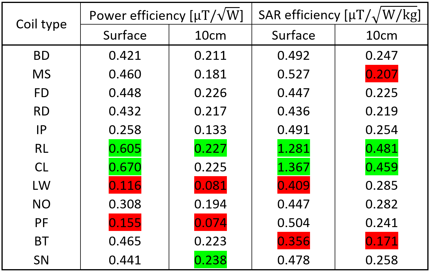
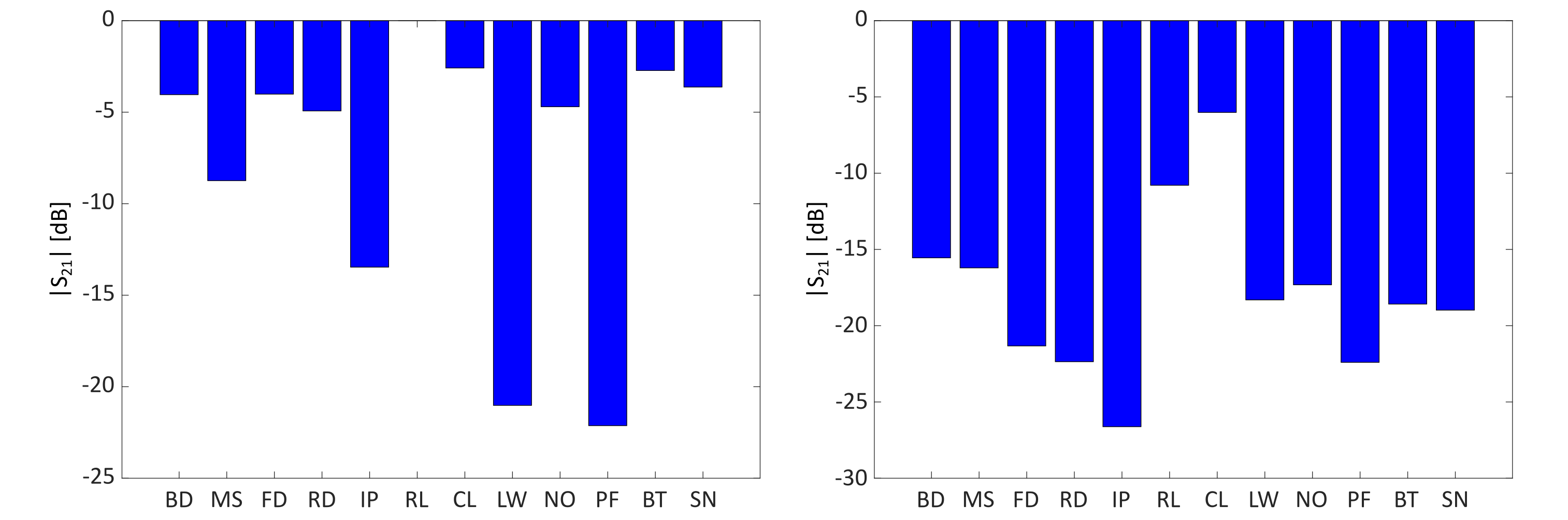
Figure 3 depicts the results of the power efficiency examination which shows that at the surface of the head the loops perform best, while the IP, LW, and PF show the lowest power efficiency. At a depth of 10cm the dipole like elements gain power efficiency relative to the loops, whereby the LW, IP, and PF are still least power efficient. The results of the SAR efficiency show that at the surface and at a depth of 10cm the loops provide best results. All other antenna types perform similarly less efficient. The intrinsic decoupling shows that the PF with |S21|=-22.1dB has the best intrinsic decoupling, followed by the LW and IP. For the RL |S21| was set to 0dB since a tuning to |S11|=-50dB was not possible without additional decoupling actions. The results for the decoupling examination as well as for the load dependence are depicted in figure 4. Here, it can be seen, that the IP shows the lowest dependence to load changes (|S21|=-26.6dB), whereby the RL and CL (|S21|=-10.8dB and |S21|=-6.0dB respectively) show the highest dependence. The evaluation measurement shows general agreement between the simulation and the measurement (figure 5c). The error up to a distance of 190mm is below 10%, however, further inside the phantom the error increases.Discussion and Conclusion
Considering efficiencies, the loops outperform the other antenna types. This is mainly due to the lower SAR, especially at a larger depth inside the head. Furthermore, the coils having a low power efficiency show a high intrinsic decoupling. The reason is that they generate high magnetic and electric fields inside the substrate between the conductors so that less power is emitted. It must be noted that, |S21|, however, only shows coupling between the input ports, thus, |S21| of PF only represents the coupling of the short dipoles but the coupling of the passive dipoles is not directly represented by |S21|, hence the actual field distribution of the elements must be further evaluated. Considering the load dependence, it can be seen that it correlates with the SAR efficiency. The transmit elements (loops) with a high SAR efficiency have a higher load dependence and vice versa. This is based on a stronger coupling to the load, which results in a larger detuning by load changes. The variation of the validation results rest on the problem of correctly aligning the field probe to get the same entrance point for the line plots. At this point, it must be mentioned that these results are only valid for this specific setup, i.e. a large distance between transmit elements and object and that the efficiencies can vary in an array configuration due to inter-element coupling. They do, however, give insights into the coils’ performances even for other setups.For 7T head imaging it can be concluded that the choice of transmit elements depends on the use case. When power and SAR efficiency is most important as well as for transceive coils, loops seem to be the best choice, whereas for coils used with various loads or as a transmit only coil, a dipole like element (e.g., IP) may be a better choice.
Acknowledgements
This work is funded by the European Regional Development Fund under the operation number ‘’ZS/2019/02/97145‘‘.References
1. Avdievich, Nikolai I.; Solomakha, Georgiy; Ruhm, Loreen; Nikulin, Anton V.; Magill, Arthur W.; Scheffler, Klaus (2021): Folded-end dipole transceiver array for human whole-brain imaging at 7 T. In: NMR in biomedicine 34 (8), e4541. DOI: 10.1002/nbm.4541.
2. Rietsch, Stefan H. G.; Quick, Harald H.; Orzada, Stephan (2015): Impact of different meander sizes on the RF transmit performance and coupling of microstrip line elements at 7 T. In: Medical physics 42 (8), S. 4542–4552. DOI: 10.1118/1.4923177.
3. Raaijmakers, Alexander J. E.; Italiaander, Michel; Voogt, Ingmar J.; Luijten, Peter R.; Hoogduin, Johannes M.; Klomp, Dennis W. J.; van den Berg, Cornelis A T (2016): The fractionated dipole antenna: A new antenna for body imaging at 7 Tesla. In: Magnetic Resonance in Medicine 75 (3), S. 1366–1374. DOI: 10.1002/mrm.25596.
4. Clément, Jérémie; Gruetter, Rolf; Ipek, Özlem (2019): A combined 32-channel receive-loops/8-channel transmit-dipoles coil array for whole-brain MR imaging at 7T. In: Magnetic Resonance in Medicine 82 (3), S. 1229–1241. DOI: 10.1002/mrm.27808.
5. Li, Mingyan; Jin, Jin; Weber, Ewald; Engstrom, Craig; Destruel, Aurelien; Crozier, Stuart; Liu, Feng (2022): Prostate imaging with Integrated Multi-modal Antenna with coupled Radiating dipoles (I-MARS) at 7T. In: International Society of Magnetic Resonance in Medicine, Article 3228.
6. Williams, Sydney N.; Allwood-Spiers, Sarah; McElhinney, Paul; Paterson, Gavin; Herrler, Jürgen; Liebig, Patrick et al. (2021): A Nested Eight-Channel Transmit Array With Open-Face Concept for Human Brain Imaging at 7 Tesla. In: Frontiers in Physics 9, S. 412. DOI: 10.3389/fphy.2021.701330.
7. Cao, Zhipeng; Yan, Xinqiang; Gore, John C.; Grissom, William A. (2020): Designing parallel transmit head coil arrays based on radiofrequency pulse performance. In: Magnetic Resonance in Medicine 83 (6), S. 2331–2342. DOI: 10.1002/mrm.28068.
8. Solomakha, Georgiy; Svejda, Jan; Rennings, Andreas; Erni, Daniel (2020): A new RF coil for UHF MRI based on a slotted microstrip line. In: Journal of Physics Conference Series 1461, p 1-3. DOI: 10.1088/1742-6596/1461/1/012168.
9. Sadeghi-Tarakameh, Alireza; Khalichi, Bahram; Wu, Xiaoping; Metzger, Greg; Eryaman, Yigitcan (2021): Non-Uniform Dielectric Substrate (NODES) Antenna Design for Cardiac Imaging at 7T. In: International Society of Magnetic Resonance in Medicine, Article 1398.
10. Zivkovic, Irena; Castro, Catalina Arteaga de; Webb, Andrew (2019): Design and characterization of an eight-element passively fed meander-dipole array with improved specific absorption rate efficiency for 7 T body imaging. In: NMR in biomedicine 32 (8), e4106. DOI: 10.1002/nbm.4106.
11. Winter, Lukas; Özerdem, Celal; Hoffmann, Werner; Santoro, Davide; Müller, Alexander; Waiczies, Helmar et al. (2013): Design and Evaluation of a Hybrid Radiofrequency Applicator for Magnetic Resonance Imaging and RF Induced Hyperthermia: Electromagnetic Field Simulations up to 14.0 Tesla and Proof-of-Concept at 7.0 Tesla. In: PLOS ONE 8 (4), S. 1–12. DOI: 10.1371/journal.pone.0061661.
12. Steensma, Bart; van de Moortele, Pierre-Francois; Ertürk, Arcan; Grant, Andrea; Adriany, Gregor; Luijten, Peter et al. (2020): Introduction of the snake antenna array: Geometry optimization of a sinusoidal dipole antenna for 10.5T body imaging with lower peak SAR. In: Magnetic Resonance in Medicine 84 (5), S. 2885–2896. DOI: 10.1002/mrm.28297.
13. Ip, I. Betina; Emir, Uzay E.; Lunghi, Claudia; Parker, Andrew J.; Bridge, Holly (2021): GABAergic inhibition in the human visual cortex relates to eye dominance. In: Scientific Reports 11 (1), S. 17022. DOI: 10.1038/s41598-021-95685-1.
14. Ip, I. Betina; Alvarez, Ivan; Tacon, Mike; Parker, Andrew J.; Bridge, Holly (2022): MRI Stereoscope: A Miniature Stereoscope for Human Neuroimaging. In: eNeuro 9 (1). DOI: 10.1523/ENEURO.0382-21.2021.
15. Winter, L, Silemek, B, Petzold, J, et al. Parallel transmission medical implant safety testbed: Real-time mitigation of RF induced tip heating using time-domain E-field sensors. Magn Reson Med. 2020; 84: 3468– 3484. https://doi.org/10.1002/mrm.28379
Figures