4581
Eight-channel transceiver array for combined head and neck imaging at 7 Tesla1Imaging Centre of Excellence, University of Glasgow, Glasgow, Scotland, 2MRI Physics, NHS Greater Glasgow and Clyde, Glasgow, Scotland
Synopsis
Keywords: High-Field MRI, RF Arrays & Systems, Neurovascular imaging
Combined full brain and neck MRI has been proven inevitable in diagnosis of variety of neurodegenerative diseases such as multiple sclerosis, and amyotrophic lateral sclerosis. High spatial resolution and signal-to-noise ratio provided by the ultra-high field MRI systems (>7T) could be valuable in identification of such subtle morphologies which are not noticeable at standard MRI systems. Current state-of-the-art requires change of coil for imaging either brain or C-spine or equipped with 16-channel transmission capability. This work presents the design and validation of novel neurovascular transceiver array with 8 channels (industry standard) for combined head and neck imaging at 7T.Introduction
Earlier diagnosis of pathological characteristics in the brain and spinal cord such as tumors, vascular malformations, and neurodegenerative diseases is important to reduce the associated mortality and disability rates. The ease of identification of such small lesions can be greatly enhanced with the ultra-high field MRI system (7T and above) due to its improved spatial resolution and signal to noise ratio compared to the standard MRI field strength systems1,2. Currently available brain and cervical spinal cord coils are either equipped with 16-transmit channels which are not supported by most scanners or being used individually to image the different regions of the neurovascular anatomy3,4. For simultaneous head-neck imaging, dedicated RF coil with ability to excite larger field of view than the existing brain coils is required. This work presents a novel 8-channel transceiver array and demonstrate its extended longitudinal coverage. This array will be combined with a receive-only array for head and neck imaging at 7T, with a final coil configuration consisting of 8-transceive and 56-receive only elements.Methods
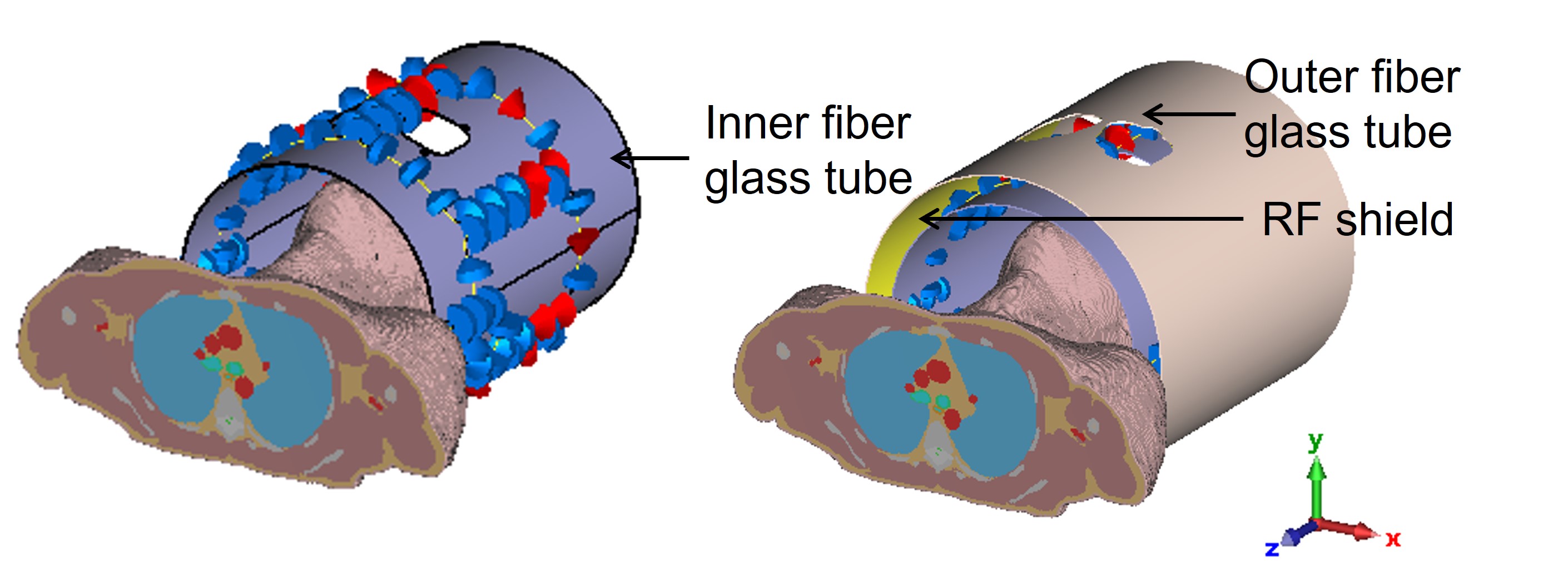
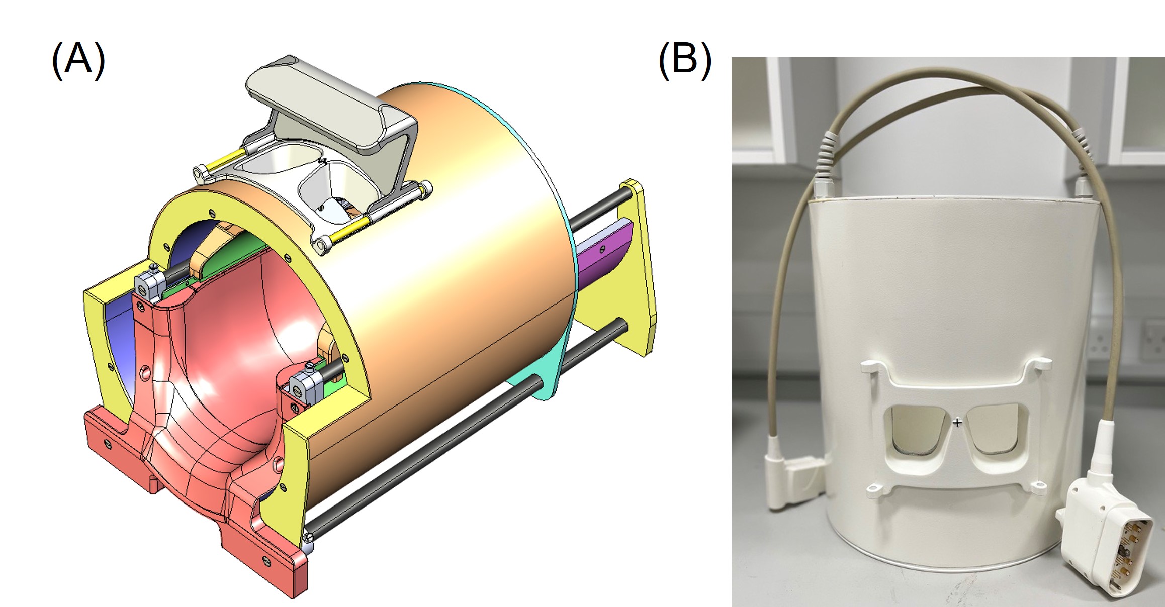
The array consists of eight conventional transceiver loops (TxRx) arranged on a fiberglass tube with an inner diameter of 290mm. The coil elements are arranged in two rows, with six elements in the top row with an angular separation of 60° and the remaining two elements are in the lower row to cover the neck and to extend the longitudinal coverage. A screenshot of the coil model in CST Studio Suite 2021 (Dassault Systems, France) is provided in Figure 1. Each loop consisted of evenly distributed fixed capacitors and a variable capacitor, and the capacitors are connected with 2mm diameter silver plated copper wire. A slotted RF shield made up of two-layer flexible PCB with 18 μm thick copper plane was attached to the inner surface of the outer fiber glass tube as in Figure 1. Two cut-outs of 70 × 65 mm2 were introduced in front of the eyes for patient comfort. All adjacent elements within the row are decoupled with transformers and the elements between the two rows are partially overlapped. 3D electromagnetic and circuit co-simulation were carried out in CST. The coil was tuned and matched to a head-shoulder phantom filled with tissue equivalent solution (εr = 52.1, σ = 0.41 S/m). The coil is then loaded with Duke voxel model from virtual family5 for B1+ shimming and SAR assessment. The constructed 8-channel transceiver array and the finalized CAD model of the proposed 8TxRx56Rx neurovascular coil is shown in Figure 2. The transceiver array also consisted of built-in TR switches. MR measurements of the coil were performed on MAGNETOM Terra 7T whole body scanner (Siemens Healthcare GmbH, Germany). The relative phase of channel 7 and 8 has been optimized to maximize the B1+ field distribution in the neck region without comprising the field distribution in the head region. To demonstrate the longitudinal coverage, B1+ maps were acquired by exciting only the elements in the top row, exciting only the lower row elements and with all elements combined. A high-resolution sagittal turbo spin echo (TSE) scan of the phantom with 340 mm longitudinal FOV by exciting all 8 channels was also obtained.Results and Discussion
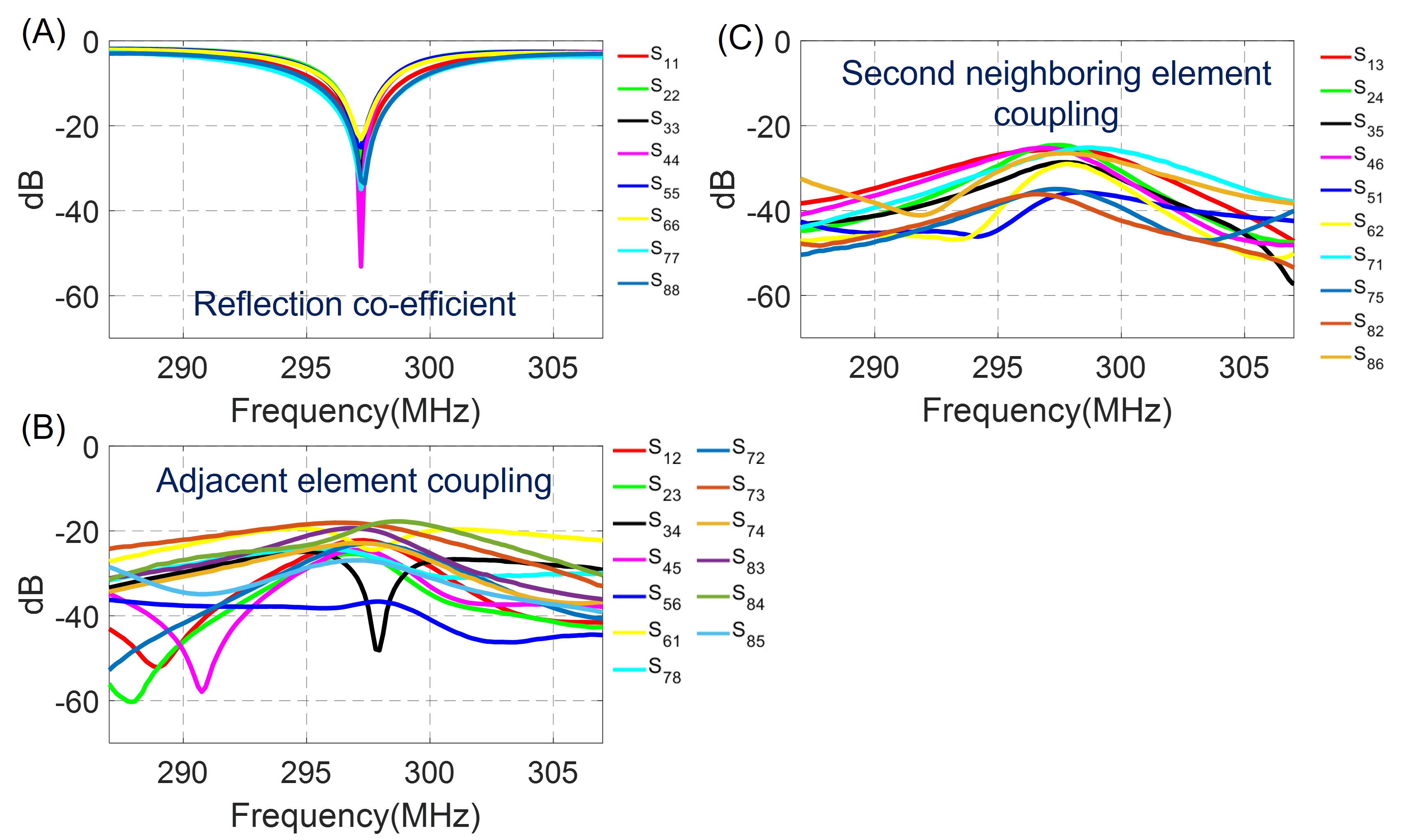
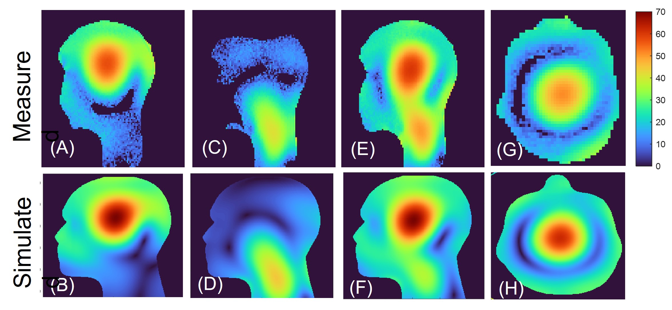
Figure 3 shows the reflection co-efficient of each channel and coupling between adjacent and second neighboring elements. The power reflection coefficient of all elements is <−25.1 dB which indicates that at least 99.7% of the input power is coupled to each element. The average mutual coupling between adjacent and second neighboring elements are -24.64 dB and -29.4 dB, respectively. The simulated 10 g-peak SAR for 1W input power in the duke model is 0.3 W/kg in CP configuration. Figure 4 (A-F) shows the measured and simulated B1+map in the central sagittal plane of phantom while exciting only top row elements, bottom row elements, and all 8 elements. It is evident that the field coverage in the head region induced by channel 1 to 6 is similar to the conventional brain coil3. Also, channel 7 and 8 in the bottom row extend the longitudinal field coverage to the neck region. Figure 4 (G-H) shows the symmetric field distribution induced by channel 1 to 6 in the axial midplane. The measured average B1+ field in the neck region in central sagittal slice while exciting all 8 channels and top 6 channels is 32.01 nT/V and 11.64 nT/V, respectively. Whereases, measured average B1+ in the head region in central sagittal slice while exciting all 8 channels and top 6 channels is 36.1 nT/V and 36.41 nT/V, respectively. Combined head and neck coverage that can be achieved with this novel transmit array configuration is also demonstrated in the TSE image shown in Figure 5.Conclusion
The simulated and measured results confirm that the proposed 8-channel transceiver array can extend the field coverage to the neck region without compromising the field distribution in the head region compared to existing head coils at 7T. Future work will involve construction of 56-channel receive only array which will be combined with the constructed 8-transceive elements for neurovascular imaging.Acknowledgements
This project is funded by SINAPSE, Christine Rodgers endowment fund, Neuroscience Foundation and UKRI strength in places fund.References
[1] Y. Li et al., "One-Stop MR Neurovascular Vessel Wall Imaging With a 48-Channel Coil System at 3 T," (in eng), IEEE Trans Biomed Eng, vol. 67, no. 8, pp. 2317-2327, Aug 2020.
[2] M. W. May et al., "A patient-friendly 16-channel transmit/64-channel receive coil array for combined head-neck MRI at 7 Tesla," Magn Reson Med, vol. 88, no. 3, pp. 1419-1433, Sep 2022.
[3] S. N. Williams et al., "A Nested Eight-Channel Transmit Array With Open-Face Concept for Human Brain Imaging at 7 Tesla," Frontiers in Physics, vol. 9, July 2021.
[4] W. Zhao et al., "Nineteen-channel receive array and four-channel transmit array coil for cervical spinal cord imaging at 7T," Magn Reson Med, vol. 72, no. 1, pp. 291-300, Jul 2014.
[5]Christ A, Kainz W, Hahn EG, et al. The Virtual Family--development of surface-based anatomical models of two adults and two children for dosimetric simulations. Phys Med Biol. 2010;55(2):N23-N38.
Figures