4580
Prostate Imaging at 7 Tesla: Comparison of Two 8-channel Transmit/Receive RF Local Body Arrays1Erwin L. Hahn Institute for MRI, University Duisburg-Essen, Essen, Germany, 2High-Field and Hybrid MR Imaging, University Hospital Essen, Essen, Germany, 3Department of Medical Imaging, Radboud University Medical Center, Nijmegen, Netherlands, 4Medical Physics in Radiology (E020), German Cancer Research Center (DKFZ), Heidelberg, Germany, 5DZHK (German Center for Cardiovascular Research), DZHK (German Center for Cardiovascular Research), Partner Site Berlin, Berlin, Germany, 6Tesla Dynamic Coils, Zaltbommel, Netherlands
Synopsis
Keywords: RF Arrays & Systems, Body
The purpose of this study is to compare two different coil array designs for prostate imaging. We compared an in-house developed 8chpTx/Rx micro stripline element coil array with meanders to a recently introduced, commercially available 8chpTx/Rx coil array based on fractionated dipoles for 1H prostate imaging at 7T. Both coil arrays showed comparable results in the phantom and in vivo examinations. The commercially available coil array performs slightly better in the region of the prostate and is well suited for future prostate imaging at 7T.
Introduction
Ultrahigh-field (UHF) MRI at 7T provides capabilities to better characterize intraprostatic lesions and the potential to improve accuracy in treatment planning. [1] Even standard 1H imaging at UHF enables the detection of small lesions which are often not depictable at clinical field-strengths of 1.5T and 3T [2,3]. The potential role of prostate imaging at 7T could be in achieving a better understanding of the development and progression of local prostate cancer, the onset and spatial distribution of metastatic spread, and in characterization of different tumor stages and recurrent disease [4]. However, the performance of imaging substantially benefits from RF coil designs fulfilling requirements like efficiency and coupling between individual RF elements [5,6]. Previous work showed that an array of eight transmit dipoles appears to be most favorable for potential use in 7T body MRI [7].In this study, we compared the performance of one custom-built 8-chpTx/Rx [8] built of micro stripline elements with meanders named Coil A (Fig. 1left) with a commercially available coil with 8-chpTx/Rx built of fractionated dipole antennas (Tesla Dynamic Coils B.V., the Netherlands) named Coil B (Fig. 1right).Methods
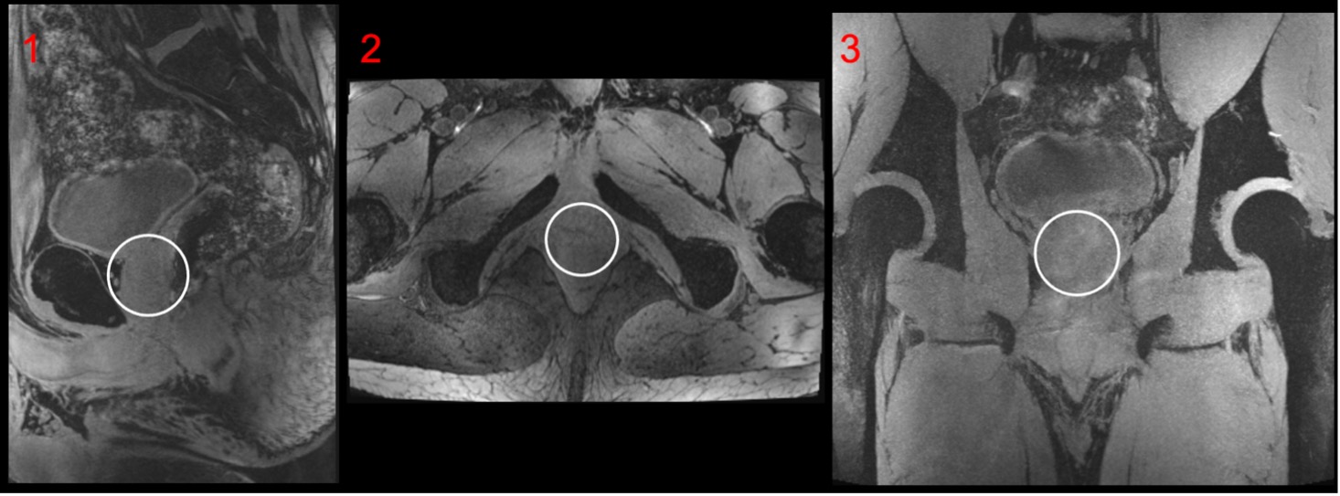
MR imaging was performed on a 7T MRI system (MAGNETOM Terra, Siemens Healthcare GmbH, Germany) equipped with 8ch pTx system. The study was approved by the institutional MR safety board and informed consent was obtained from a single participant (age: 23, sex: male, height/weight: 1.90 m/90 kg). The micro stripline elements of Coil A are 250mm and the fractionated dipoles of Coil B are 316 mm in length. Both coils feature an integrated additional receive array. Coil A has an additional 24chRx 1H loop array whereas Coil B has an additional 4Tx/Rx/24chRx RF array for 31P beneath the 1H Tx elements (Fig. 2). Within the scope of comparison, both additional coil array structures of Coil A and Coil B where deactivated on the scanner, leaving only the 8ch Tx/Rx elements for 1H activated. All performance comparisons were done with a transmitter reference voltage of 500 V. Quantitative comparisons were performed on the same cylindrical body-sized phantom (fig.2) filled with tissue-simulating liquid (ԑr = 46.3, σ = 0.8 Ω−1 m−1) to reflect a typical body load. Flip angle (FA) maps were obtained using the 3DREAM technique [9]. In vivo FA datasets of one subject were acquired with both coil arrays.SNR maps were obtained from a reference GRE scan using an optimal coil combination weighted by the inverse of the noise covariance matrix obtained from a service sequence on the scanner (coil utils, VE12U). Slice profiles were generated for both coils in the phantom and in vivo (fig.3). Images were evaluated qualitatively regarding artefacts and homogeneity over the prostate region and across slices. After starting with a circular polarized excitation (CP+, 45° phase increment) a phase-only optimization for a B1+-efficient excitation within the region-of-interest (ROI) was performed offline in MATLAB R2020a (MathWorks, Natick, MA, USA) based on exported relative B1+ maps [10,11] (fig.4). The phase settings with equal amplitudes were then manually updated on the scanner console. A manually drawn ROI in the prostate was set. The mean FA was measured for both coils in the ROI. Finally, prostate images acquired with Coil B and RF TIAMO shimming [12] are presented (fig.5).
Results
Coil housing comparison shows improved patient comfort due to the integrated foam of Coil B. The RF elements of Coil A are closer to the subject of investigation and show improved SNR in the periphery of the phantom. However, the slice profile and the prostate ROI are comparable with a slight advantage for Coil B. Qualitative measured in vivo FA map in the ROI of both coils in the prostate shows comparable results with the static shimming and 0.9° difference in respect to the chosen ROI.The B1+field of Coil A and Coil B show similar results in the ROIs. However, when the shimming approach is applied, Coil B has a slight advantage of 2.7% and creates higher B1+field in the chosen ROI. Figure 5 shows the in vivo MRI with the GRE TIAMO sequence of the prostate.
Discussion
We evaluated the Tx/Rx performance of two different 8ch Tx/Rx body RF coils with the goal of enabling 7T prostate imaging and the detection of small lesions with the new, commercially available RF coil in the future. Overall, both coils showed comparable results. The slight advantage of Coil B can be explained through the more morphologically shaped bottom coil former. Coil B shows a very well-integrated coil design that fits into the MAGNETOM Terra MR system, whereas Coil A was originally designed for the patient table of the older MAGNETOM 7T MRI system. Both RF coils yielded satisfying image quality for the prostate region. Workflow improvements were particularly noted with the robust coil design of Coil B since the interface setup is integrated in the upper posterior body part of Coil B. The additional option of enabling the 4Tx/Rx/24chRx for 31P Rx coil array for 7T Coil B is very well suited for multiparametric prostate imaging at 7T in the future. Future work will focus on assessing the reproducibility in larger studies involving subjects with varying body mass indices.Acknowledgements
The Coil B used in this work was constructed with support from the European Fund for Regional Development EFRO OP-2014-2023-Oost [PROJ-01009].References
[1] Rothberg MB, Enders JJ, Kozel, Z, Gopal N, Turkbey B, Pinto PA, The role of novel imaging in prostate cancer focal therapy: treatment and follow-up. Current Opinion in Urology: May 2022 - Volume 32 - Issue 3 - p 231-238 doi:10.1097/MOU.0000000000000986
[2] Sharma HK, Feldman R, Delman B, et al. Utility of 7 Tesla MRI brain in 16 “MRI negative” epilepsy patients and their surgical outcomes. Epilepsy Behav Rep 2021;15:100424.
[3] Feldman RE, Delman BN, Pawha PS, et al. 7T MRI in epilepsy patients with previously normal clinical MRI exams compared against healthy controls. PLoS One 2019;14:e0213642.
[4] Tenbergen, C.J.A., Metzger, G.J. & Scheenen, T.W.J. Ultra-high-field MR in Prostate cancer: Feasibility and Potential. Magn Reson Mater Phy 35, 631–644 (2022). https://doi.org/10.1007/s10334-022-01013-7
[5] Roemer, P.B., Edelstein, W.A., Hayes, C.E., Souza, S.P. and Mueller, O.M. (1990), The NMR phased array. Magn Reson Med, 16: 192-225. https://doi.org/10.1002/mrm.1910160203
[6] Keil B, Wald LL. Massively parallel MRI detector arrays. J Magn Reson. 2013 Apr;229:75-89. doi: 10.1016/j.jmr.2013.02.001. Epub 2013 Feb 7. PMID: 23453758; PMCID: PMC3740730.
[7] Rietsch, S.H.G., Orzada, S., Bitz, A.K., Gratz, M., Ladd, M.E. and Quick, H.H. (2018), Parallel transmit capability of various RF transmit elements and arrays at 7T MRI. Magn. Reson. Med, 79: 1116-1126. https://doi.org/10.1002/mrm.26704
[8] Rietsch, S., Orzada, S., Maderwald, S., Brunheim, S., Philips, B., Scheenen, T., Ladd, M. E., & Quick, H. H. (2018). 7T ultra-high field body MR imaging with an 8-channel transmit/32-channel receive radiofrequency coil array. Medical physics, 45(7), 2978–2990. https://doi.org/10.1002/mp.12931
[9] Ehses P, Brenner D, Stirnberg R, Pracht ED, Stocker T. Whole-brain B1 -mapping using three-dimensional DREAM. Magnetic resonance in medicine. 2019;82(3):924-934
[10] Van de Moortele P. Very fast multi channel B1 calibration at high field in the small flip angle regime. Paper presented at: Proc. 17th Annual Meeting ISMRM2009; Honolulu, HI.
[11] Schmitter S, Wu X, Adriany G, Auerbach EJ, Ugurbil K, Moortele PF. Cerebral TOF angiography at 7T: Impact of B1 (+) shimming with a 16-channel transceiver array. Magnetic resonance in medicine. 2014;71(3):966-977.
[12] Schulz J, Kraff O, Quick H, Scheenen T. A Software-based TIAMO approach to enable high resolution large FOV body imaging at 7T ultra-high field Pro. 31st Annual Meeting ISMRM 2022 London, UK
Figures
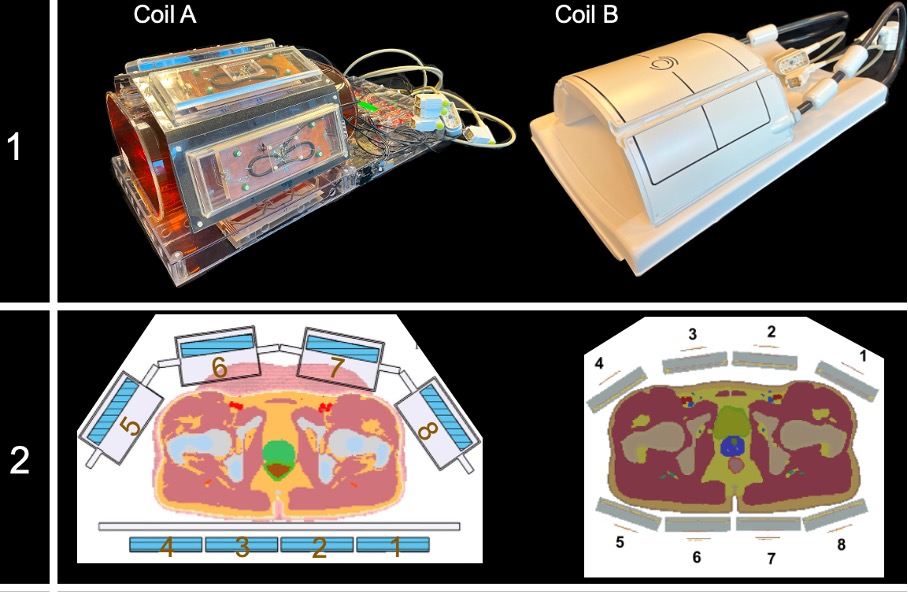
Row 1: Coil housings. Coil A is a custom-built flexible 8-chpTx/Rx for 1H is with 24 additional 1H Rx channels compared with a commercially available flexible Coil B which supports 8-chpTx/Rx for 1H and 4Tx/Rx/24chRx for 31P.
Row 2: Coil layout. Coil A shows a flat layout of the lower TX/Rx antennas where Coil B has a more morphological shaped lower layout.
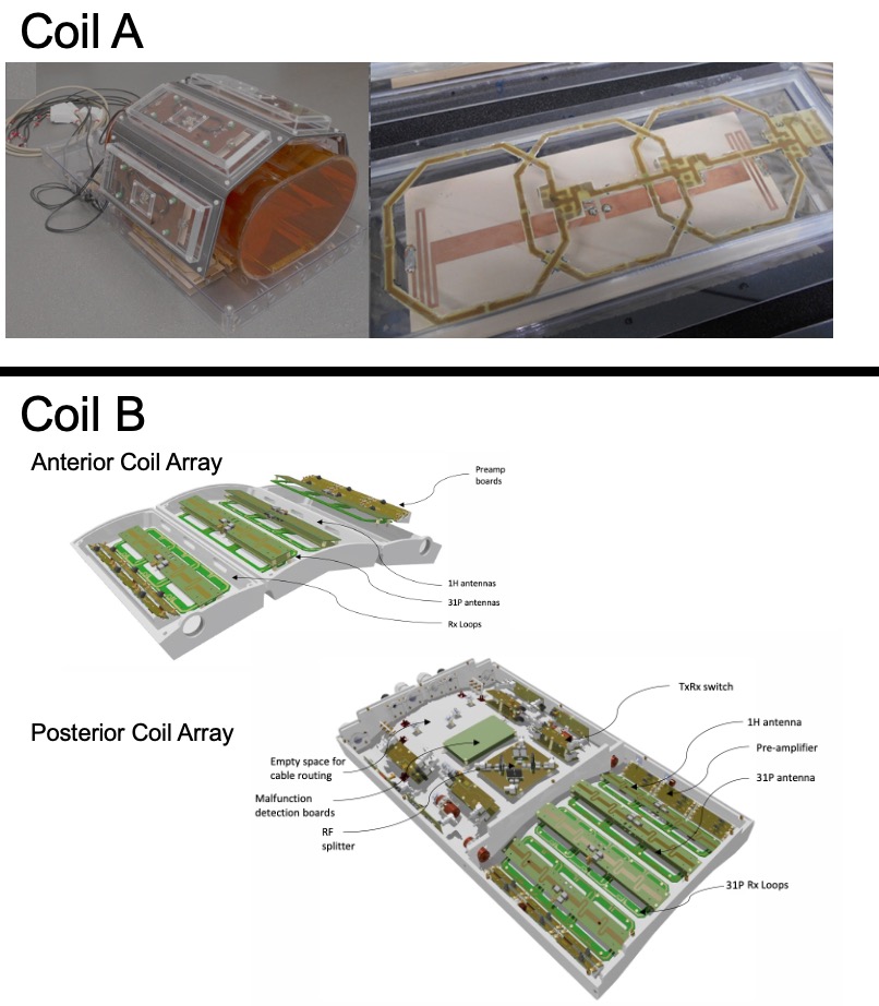
Mechanical setup with the deactivated RX loops of Coil A in the upper area. The anterior and posterior meander Tx/Rx array design of Coil B with the deactivated 31P loops of Coil B in the lower area. Each part is holding 4 1H transceiver dipole meander antennas maintaining an offset to the two 31P transceiver antennas and the 12 local 31P receiver array.
The posterior coil array is spit into the transceiver section and houses the antennas where the interface section supports the integrated Tx/Rx and the TR switch.
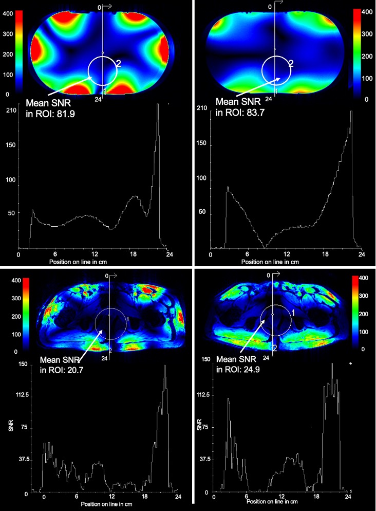
Upper left and upper right: Measured SNR comparison of Coil A and Coil B in a phantom with CP+ excitation and fixed reference voltage. Center row shows SNR slice profiles. The ROI in the prostate region in Coil B shows a 2.2% higher mean SNR compared to Coil A. Slice profiles below are comparable.
Lower left and lower right: Measured in vivo SNR in one ROI and one slice. The ROI in Coil B shows 16.9% higher SNR compared to Coil A. The slice profile shows slightly more SNR in Coil B in the periphery.
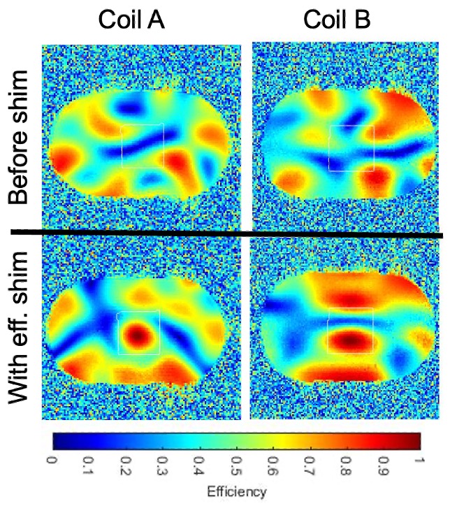
First row: combined 8ch B1+field of Coil A and Coil B before phase RF shim. In the ROI Coil A shows an efficiency of 39.4% where Coil B has 39%. Second row shows the prediction for a B1+-efficient shim for Coil A (60.8%) and Coil B (62.5%). Coil B performs 2.7% better with the chosen shimming setting.